Area Delay Efficient FM0/Manchester Encoding Using SOLS
Technique Using Wireless Sensor Network for Communication
Applications
Sankati Swathi & Minhaz Sultana
[email protected], [email protected]
1Dept of Electronics Engineering, CJITS, Jangaon, Warangal, TS, India,ABSTRACT:
In this paper we contemplated the execution of
Manchester coding is being
described.Manchester coding strategy is a advanced coding procedure in which every one of the bits of the parallel information are organized in a specific arrangement. The Intersil HD-15530 is a high execution CMOS gadget proposed to benefit the prerequisites of MlL-STD-1553 what's more, comparable
Manchester II encoded, time division
multiplexed serial information conventions. This LSI chip is partitioned into two segments, an Encoder and a Decoder. These areas work totally free of each other, with the exception of the Master Reset capacities. This circuit meets a significant number of the prerequisites of MILSTD-1553. The Encoder produces the match up beat and the equality bit and the encoding of the information bits. The Decoder perceives the synchronize beat and distinguishes it and also interpreting the information bits and checking equality. This incorporated circuit is completely ensured to bolster the 1MHz information rate of MlL-STD- 1553 over both temperature and voltage. It interfaces with CMOS, TTL or N channel bolster hardware. The HD-15530 can likewise be utilized as a part of many partisan division advanced information correspondences applications, for example, an ecological control framework driven from a solitary wound match link of fiber optic link all through the building. The elements of the encoder area of the MED incorporate a microchip interface, parallel to serial transformation, outline age, and NRZ to Manchester encoding. This hardware can run extremely quick since it doesn't require a high-recurrence clock. The edge arrange utilized is
like that of a UART. The Manchester decoder constrains the most extreme recurrence of operation of the MED, since it utilizes a high-recurrence clock. The beneficiary hardware is more intricate, since clock recuperation and focus examining is finished. Extra beneficiary capacities are outline location, deciphering of Manchester to NRZ, serial to parallel transformation, and a chip interface.
Keywords: Manchester coding, Encoder,
Decoder, NRZ, Moore’s law, UART, clock frequency
I. INTRODUCTION
from high to low or low to high for each piece. Consequently for a recipient it is less demanding to distinguish the information in Manchester organize and furthermore the likelihood for event of a mistake is low in Manchester organize and it is an all around acknowledged advanced encoding procedure. The committed short range correspondence is a convention for maybe a couple way medium range correspondence. The DSRC can be quickly arranged into two classes: car to-car and car to roadside. In car to-car, the DSRC empowers the message sending and broadcasting among car. The car to-roadside concentrates on the canny transportation benefit, for example, electronic toll accumulation (ETC).The DSRC engineering having the handset. The handset having the baseband preparing, RF front end and microchip. The microchip is utilized to exchange the direction to the baseband handling and RF front end. the RF front end is utilized to transmit what's more, get the remote signs utilizing the receiving wire. The baseband preparing is mindful for balance,
mistake rectification, encoding and
synchronization. The transmitted flag comprises of the self-assertive twofold arrangement, it is exceptionally hard to get the dc-balance.the fm0 and Manchester are give the transmitted flag and
afterward the dc-adjust. The (SOLS)
comparability arranged rationale rearrangements having the two strategies: region conservative retiming and adjust rationale operation sharing. The region minimized retiming used to diminish the transistor tallies .the balance rationale operation sharing is utilized to join the fm0 and Manchester encoding.
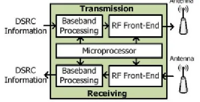
Fig. 1. System architecture of DSRC transceiver.
The framework engineering of DSRC handset is appeared in Fig. 1. The upper and base parts are committed for transmission and getting, individually. This handset is characterized into three essential modules: microchip, baseband handling, and RF front-end. The microchip deciphers guidelines from media get to control to plan the undertakings of baseband preparing and RF front-end. The baseband preparing is capable for adjustment, mistake redress, clock synchronization, and encoding. The RF frontend transmits and gets the remote flag through the recieving wire. The DSRC guidelines have been built up by a few associations in various nations. These DSRC guidelines of America, Europe, and Japan are appeared in Table I. The information rate separately focuses at 500 kb/s, 4 Mb/s, and 27 Mb/s with bearer recurrence of 5.8 and 5.9 GHz. The balance techniques join sufficiency move keying, stage move keying, and orthogonal recurrence division multiplexing. For the most part, the waveform of transmitted flag is anticipated that would have zero mean for heartiness issue, what's more, this is additionally alluded to as dc-adjust.
II. Literature Survey
The transmitted flag comprises of subjective paired succession, which is hard to acquire dc-adjust. The reasons for FM0 and Manchester codes can give the transmitted motion with dc-adjust. Both FM0 and Manchester codes are generally received in encoding for downlink. The VLSI structures of FM0 furthermore, Manchester encoders are surveyed as takes after
A. Audit of VLSI Architectures for FM0 Encoder and Manchester Encoder
the most extreme operation recurrence is as high as 5 GHz. The writing [6] builds up a rapid VLSI engineering nearly completely reused with Manchester and Miller encodings for radio
recurrence distinguishing proof (RFID)
applications. This plan is acknowledged in 0.35-μm CMOS innovation and the greatest operation recurrence is 200 MHz. The writing [7] likewise proposesa Manchester encoding engineering for ultrahigh recurrence (UHF) RFID label emulator. This equipment engineering is directed from the limited state machine (FSM) of Manchester code, and is acknowledged into field-programmable door cluster (FPGA) prototyping framework. The most extreme operation recurrence of this outline is around 256 MHz. The comparative outline philosophy is additionally connected to independently develop FM0 and Miller encoders additionally for UHF RFID Tag emulator [8] . Its greatest operation recurrence is around 192 MHz. Moreover, [9] consolidates recurrence move keying (FSK) balance and demodulation with
Manchester codec in equipment
acknowledgment.
III. CODING PRINCIPLES OF FM0 CODE AND MANCHESTERCODE
In the accompanying exchange, the clock flag and the info information are condensed as CLK, what's more, X, separately. With the above parameters, the coding standards of FM0 and Manchester codes are talked about as takes after.
A. FM0 Encoding As appeared in Fig. 2, for each X, the FM0 code comprises of two sections: one for previous half cycle of CLK, An, and the other one for some other time half cycle of CLK,B. The coding guideline of FM0 is recorded as the accompanying three rules.
1) If X is the rationale 0, the FM0 code must display a progress amongst An and B.
2) If X is the rationale 1, no progress is permitted amongst An and B.
3) The progress is distributed among each FM0 code regardless of what the X is. A FM0 coding illustration is appeared in Fig.
3. At cycle 1, the X is rationale 0; thusly, a progress happens on its FM0 code, as indicated by govern 1. For effortlessness, this change is at first set from rationale 0 to - 1. As per control 3, a progress is allotted among each FM0 code, and in this manner the rationale 1 is changed to rationale 0 in the start of cycle 2. At that point, as per lead 2, this rationale level is hold with no change in whole cycle 2 for the X of rationale 1. Along these lines, the FM0 code of each cycle can be determined with these three guidelines said before.
Illustration of FM0 coding example.
Hardware Architecture Of Fm0/Manchester Code:
This is the equipment engineering of the fm0/Manchester code. the best part is signified the fm0 code and after that the base part is signified as the Manchester code. in fm0 code the DFFA and DFFB are utilized to store the state code of the fm0 code and furthermore mux_1 and not door is utilized as a part of the fm0 code. At the point when the mode=0 is for the fm0 code. The Manchester code is produced just utilizing the XOR door and when the mode=1 is for the Manchester code. the equipment usage rate is characterized as the accompanying
Hardware architecture
The dynamic parts implies the parts are work in the both fm0 and Manchester code. The aggregate parts implies the quantity of the parts are available in the gap circuit. the HUR rate is given underneath the following segment
For both the encoding techniques the aggregate segments is 7.for the fm0 code the aggregate segment is 7 and after that the dynamic segment is 6.in Manchester code the aggregate segment is 7 the dynamic segment is 2.in both coding having 98 transistors are utilized without SOLS. The fm0 having 86 transistor, and after that the Manchester having the 26 transistor. the normal for both coding is 56 transistors .In proposed work diminish the aggregate parts from 7 to 6 and diminish the transistor checks. In this paper two multiplexer is utilized as a part of proposed work diminish two multiplexer from one multiplexer, when diminish the multiplexer the aggregate parts are decreased the zone and afterward the power utilization too lessened
IV. FMO and Manchester Encoder Using Sols Technique:
The SOLS method is grouped into two parts region smaller retiming and adjust rationale operation sharing
A. area compact retiming
Area compact retiming
FM0 encoding without area compact retiming
The previous state is denoted as the A(t-1) and then the B(t-1).and then the current state is denoted as the A(t) and then the B(t).
FM0 encoding with area compact retiming.
In this way, the FM0 encoding just requires a single 1-bitflip-flounder to store the past esteem B(t−1).If the DFFA is specifically expelled, a non synchronization amongst A(t) and B(t)causes the rationale blame of FM0 code. To keep away from this rationale blame, the DFFB is moved directly after the MUX−1, where the DFFB is accepted be sure edge activated flip slump. At each cycle, the FM0 code, including An and B, is gotten from the rationale of A(t) and the rationale of B(t), separately. The FM0 code is on the other hand exchanged amongst
A(t) and B(t) through the MUX−1 by the control flag of the CLK. In the Q of DFFB is straightforwardly refreshed from the rationale of B(t)with 1-cycle idleness. at the point when the CLK is rationale 0, the B(t) is gone through MUX−1 to the D of DFFB. At that point, the up and coming positive-edge of CLK refreshes it to the Q of DFFB. the planning graph for the Q of DFFB is predictable whether the DFFB is migrated or not. the B(t) is gone through MUX−1 to the D of DFFB. At that point, the up and coming positive-edge of CLK refreshes it to the Q of DFFB. the planning outline for the Q of DFFB is reliable regardless of whether the DFFB is migrated or not. The transistor tally of the FM0 encoding engineering without region reduced retiming is 72,and that with zone minimized retiming is 50. The zone minimized retiming procedure diminishes 22 transistors.
B. Balance logic operation sharing
The Manchester encoding is determined utilizing the XOR operation. the condition of the XOR door is given underneath.
X ⊕CLK=X CLK+~ X CLK
the idea of adjust rationale operation sharing is to coordinate the X into A(t) and X into B(t).the fm0 and Manchester rationales have a basic purpose of the multiplexer like rationale with the determination of the CLK. the graph for the balance rationale operation sharing given the following.
Balance logic operation sharing
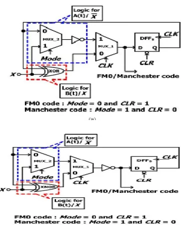
By the by, this design displays a disadvantage that the XOR is just devoted for FM0 encoding, and isn't imparted to Manchester encoding. Hence, the HUR of this engineering is absolutely restricted. The X can be likewise deciphered as the X 0, and in this manner the XOR operation can be imparted to Manchester and FM0 encodings, where the multiplexer reckless to switch the operands of B(t−1) furthermore, rationale 0. This design shares the XOR for both B(t) and X, and there by builds the HUR. At the point when the FM0 code is embraced, the CLR is handicapped, and the B(t −1) can be gotten from DFFB .Hence, the multiplexer can be completely spared, and its capacity can be totally coordinated into the moved DFF. The rationale for A(t)/X incorporates the MUX−2 and an inverter. Rather, the rationale for B(t)/X just consolidates a XOR entryway. In the rationale for A(t)/X, the calculation time of MUX−2is relatively indistinguishable to that of XOR in the rationale for B(t)/X. Be that as it may, the rationale for A(t)/X further consolidates an inverter in the arrangement of MUX−2. This unbalance calculation time between A(t)/X and B(t)/X brings about the glitchto MUX−1,possibly causing the logic fault on coding. To mitigate this unbalance calculation time, the engineering of the balance calculation time between A(t)/X and B(t)/X The XOR in the rationale for B(t)/X is converted into the XNOR with an inverter, and after that this inverter is imparted to that of the rationale for A(t)/X. This mutual inverter is migrated in reverse to the yield of MUX−1. Along these lines, the rationale calculation time
between A(t)/X what's more, B(t)/X is more adjust to each other.
Fig. 12. VLSI engineering of FM0 and Manchester encodings utilizing SOLS system. (a) Unbalance calculation time between A(t)/Xand B(t)/X. (b) Balance calculation time between A(t)/XandB(t)/X.
The reception of FM0 or Manchester code relies upon Mode and CLR. Likewise, the CLR additionally has another individual capacity of a equipment instatement. On the off chance that the CLR is just determined by transforming Mode without allotting an individual CLR control flag, this prompts a struggle between the coding mode choice and the equipment introduction. To keep away from this struggle, both Mode and CLR are thought to be independently allotted to this plan froma framework controller. Regardless of whether FM0 or Manchester code is embraced, no rationale segment of the proposed VLSI design is squandered. Each segment is dynamic in both FM0 and Manchester encodings. In this manner, the HUR of the proposed VLSI design is enormously moved forward.
V. Simulation Results
Manchester:
RTL Schematic
Technology Schematic
VI. CONCLUSION
The coding-decent variety amongst FM0 and Manchester encodings causes the restriction on equipment use of VLSI engineering plan. A constraint investigation on equipment use ofFM0 and Manchester encodings is talked about in detail. In this paper, the completely reused VLSI design utilizing SOLS system for both FM0 and Manchester encodings is
proposed. The SOLS method disposes of the impediment on equipment use by two center systems: region reduced retiming and adjust logicoperation sharing. The region reduced retiming moves the equipment asset to lessen the transistors. The adjust rationale operation sharing effectively joins FM0 and Manchester encodings with the indistinguishable rationale segments. This paper is acknowledged in180nm innovation with an extraordinary gadget productivity. The power utilization is 29392.843nW for Manchester encoding and FM0 encoding.
REFERENCES
[1] F. Ahmed-Zaid, F. Bai, S. Bai, C. Basnayake, B. Bellur, S. Brovold, et al., ―Vehicle safety communications—Applications (VSC-A) final report,‖ U.S. Dept. Trans., Nat.
Highway Traffic Safety Admin.,
Washington,DC, USA, Rep.DOT HS 810 591, Sep. 2011.
[2] J. B. Kenney, ―Dedicated short-range communications (DSRC) standards in the United States,‖ Proc. IEEE, vol. 99, no. 7, pp. 1162– 1182,Jul. 2011.
[3] J. Daniel, V. Taliwal, A. Meier, W. Holfelder, and R. Herrtwich,―Design of 5.9 GHz
DSRC-based vehicular safety
communication,‖IEEE Wireless Commun. Mag., vol. 13, no. 5, pp. 36–43, Oct. 2006
. [4] P. Benabes, A. Gauthier, and J. Oksman, ―A Manchester code generator running at 1 GHz,‖ in Proc. IEEE, Int. Conf. Electron., Circuits Syst.,vol. 3. Dec. 2003, pp. 1156–1159.
[5] A. Karagounis, A. Polyzos, B. Kotsos, and N. Assimakis, ―A 90nm Manchester code generator with CMOS switches running at 2.4 GHz and 5 GHz,‖ in Proc. 16th Int. Conf. Syst., Signals Image Process., Jun. 2009, pp. 1–4.
Manchester and Miller encoder,‖ in Proc. Intell. Inf. Hiding Multimedia Signal Process., Sep. 2009, pp. 538–541.
[7] M. A. Khan, M. Sharma, and P. R. Brahmanandha, ―FSM based Manchester encoder for UHF RFID tag emulator,‖ in Proc. Int. Conf.Comput., Commun. Netw., Dec. 2008, pp. 1–6.
[8] M. A. Khan, M. Sharma, and P. R. Brahmanandha, ―FSM based FM0 and Miller encoder for UHF RFID tag emulator,‖ in Proc. IEEE Adv. Comput. Conf., Mar. 2009, pp. 1317– 1322.
[9] J.-H. Deng, F.-C. Hsiao, and Y.-H. Lin, ―Top down design of joint MODEM and CODEC detection schemes for DSRC codedFSK systems over high mobility fading channels,‖ in Proc. Adv. Commun. Technol. Jan. 2013, pp. 98–103.