A STUDY ON NETWORK ON CHIP [NOC]
Suved BS, Gopalaiah
1
Dept. of Electronics & Instrumentation Engineering
,
Dayananda Sagar College of Engineering
Bengaluru, (India)
2
Assistant Professor, Dept. of EIE, Dayananda Sagar College of Engineering
Bengaluru, (India)
ABSTRACT
The growing demands in the faster computation systems has led to having more interfaces with multiple processing units. Bus based systems are found to be slow when dealing with a multi-core processing system. This growing number of processing cores on a chip requires an efficient and scalable communication structure such as Network on Chip (NoC). In this paper, we look into drawbacks of bus based architecture and how NoC’s can be faster. Parallelism is one the key for having faster system hence various network topologies are studied. Torus topology is found to be best but, has additional area overhead and more delay due to global routing [10]. Further, we discuss on routing method with Dimension Order Routing (DOR). The major traffic patterns in the network are analyzed with X-Y routing algorithm.
Index Terms—Network on Chip (NoC), multicore system, Torus topology, Dimension order routing, Traffic patterns.
I.
INTRODUCTION
subsystems hanging on the same bus still had more delay. The main drawback was that the bus was not configurable. Adding a single subsystem to this bus was complicated and hence architecture was more important. Traditionally, ICs have been designed with dedicated point-to-point connections, with one wire dedicated to each signal. For large designs, in particular, this has several limitations from a physical design viewpoint. The wires occupy much of the area of the chip, and in nanometer CMOS technology, interconnects dominate both performance and dynamic power dissipation, as signal propagation in wires across the chip requires multiple clock cycles. Technology scaling allows, even more, processors and IP blocks to be integrated on a single die, challenging the on-chip communication infrastructure in terms of throughput, scalability and flexibility. To overcome these challenges, NoC has been introduced as an alternative to bus-based interconnection. Network on chip is a communication subsystem on an integrated circuit. Network on chip technology applies networking theory and methods to on-chip communication.
Traditionally networks were made when the Intellectual property (IP) blocks had to communicate with each other or with many other such blocks. These were grouped to form a network where multiple paths were given to the blocks to communicate.
Bus based architecture is found to be very slow compared to the network based design approach. Some disadvantages of the bus based architecture are that the exact number of masters and slaves hanging to it has to be known in prior as delays calculations and timing analysis can be done to analyze its throughput. If more number of masters or slaves are to be connected to the bus then the bus length increases and thus bus becomes slower. The other main disadvantage of the bus is that it will be treated as a resource and can be allocated to any one of the client hence others who need to communicate has to wait till it gives out the bus.
Network based design can avoid delays as there will be many paths to the destination from the source. The routers are one important component in achieving this. A router looks for the destination address and hence directs it to the correct destination. The crossbar is another important component and this help in the communication of multiples IP blocks in the same cycle and hence delays can be reduced.
Traffic is another parameter that plays an important role in a network. Many traffic patterns are discussed in many works. Some of them are discussed here and are found to have their own advantages. This paper describes few traffic patterns that are considered in networks configurations. The source to destination paths is decided by routing algorithm. [2]
This paper is divided as follows Section II provides an overview of Bus based system architecture and its disadvantage in parallelism. Section III describes the network topologies. Section IV is about the sub-blocks of NoC. Arbiter, crossbar and router with X-Y routing algorithm is described. In section V briefs on few traffic patterns that are generally used in NoC simulation. Section VI concludes the paper.
II.
BUS
BASED
ARCHITECTURE
Figure 1: Single bus based architecture
The bus based architecture is said to be slower as all the interface connected to it do not work at same clock speed. The bus is thus said to work at the lowest speed interface that is connected to it. Having more interfaces makes the bus to span across the chip. Resistance is directly proportional to the length of the wire and thus resistance also increases. This increase in resistance causes the delay in signal transmission as the delay is proportional to the resistance and capacitance of the transmission line.
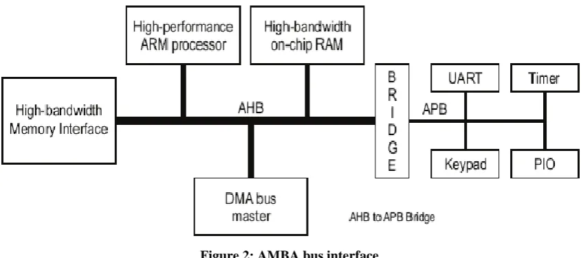
To reduce this delay the system bus is normally split into smaller bus and each bus is then connected by a bridging circuit. By doing this the transmission line delay due to RC can be addressed. The interface delays are addressed by having a different bus for interfaces with different speeds. In advance bus architectures like AMBA standards, main processors are connected to the high-speed bus. The speed of the bus is known by its working protocol. In AMBA standard AHB is said to be faster than APB.
Figure 2: AMBA bus interface
Hence main processors are connected to AHB and some slower interfaces are connected to APB. A bridging circuit is used to connect this AHB with APB. This is shown in figure 2.
III.
NETWORK
TOPOLOGY
Topology is an important parameter of NoC. It is the interconnection of the network; it defines how the network nodes are connected to each other and determine system cost, as well as performance for the network. It has a great impact on the system performance and reliability. Selection of appropriate topology can help to improve the performance of on chip communication.
3.1 Mesh:
System Bus
Processor DMA Co -Processor
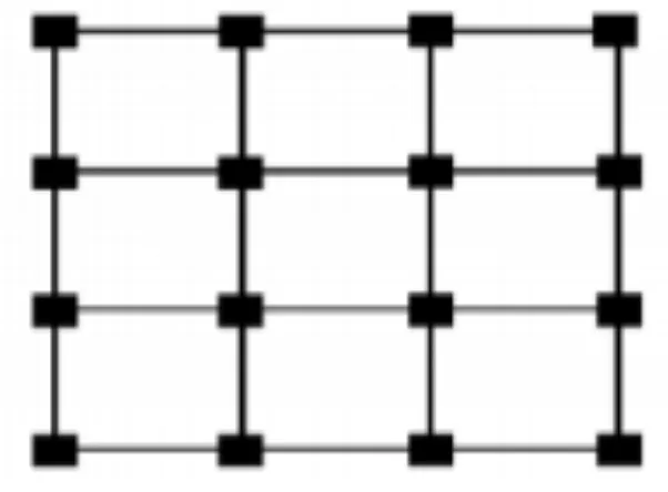
In a full mesh network, each network node is connected to every other node in the network. Due to this arrangement of nodes, it becomes possible for a simultaneous transmission of data from one node to several other nodes. [8]
Figure 3: Mesh Network
Diameter: (M+N-2)
Bisection Width: min(M,N),
Number of Routers required: (M × N),
Node Degree: 3(corner), 4(boundary), 5(central).
The nodes of a mesh network require some kind of routing logic so that the data traveling over the network take the shortest path during each of the transmission. Mesh shape network consists m columns and n rows and at each intersection, the router is situated and this router is connected to the adjacent router, it is a simple type of topology and easy to implement. 4X4 mesh architecture for NoC is as shown in figure 3. Generally, mesh network has M rows and N columns.
3.2 Torus:
Figure 4: Torus Network
Diameter: [M/2] + [N/2], Bisection Width: 2 × min (M,N), No of Routers required: (M × N), Node Degree: 5.
3.3 Ring:
In ring Topology, every node in the network is connected to two other nodes and the first and the last nodes are connected to each other. The data that are transmitted over the network pass through each of the nodes in the ring until they reach the destination node. Ring architecture for NoC is as shown in figure 5. [8]
Figure 5: Ring Topology
Diameter: N is even: N/2
N is odd: (N-1)/2. Bisection Width: 2 Node Degree: 2
IV.
SUB-BLOCKS
OF
NOC
Grant
Grant Grant
Grant Request
Request Available
Available
header containing the destination address. The routers thus look into this headers and route to their destination IPs. A priority based flow control is used to control the grants that are given to a client by the arbiter.
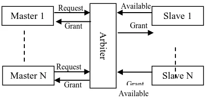
4.1 Arbiter
The arbiter controls the arbitration of the ports and resolves contention problem. It keeps the updated status of all the ports and knows which ports are free and which ports are communicating with each other. Packets requesting for same output port are scheduled with priority based arbitration. Suppose at the same time, there are many input ports request the same output or resource, the arbiter gives a grant to any one inputs based on the scheduling algorithm. The arbiter will release the grant on a port which is connected by crossbar once the last packet has finished transmission.
Figure 6: Block Diagram of Arbiter
So that other waiting packets could use the output by the arbitration of arbiter. A round - robin arbiter operates on the principle that a request which was just served should have the lowest priority on the next round of arbitration. Depending upon the control logic, arbiter generates a control signal for select lines in a multiplexer based crossbar and read or write signal for FIFO buffer. Contention resolution is an important task of arbiter.
4.2 Crossbar
The crossbar switch is a collection of switches arranged in a matrix configuration. A crossbar switch has multiple input and output lines that form a crossed pattern of interconnecting lines between which a connection may be established by closing a switch located at each intersection, the elements of the matrix. Originally, a crossbar switch consisted literally of crossing metal bars that provided the input and output paths.
A crossbar switch is an assembly of individual switches between a set of inputs and a set of outputs. The switches are arranged in a matrix. If the crossbar switch has M inputs and N outputs, then a crossbar has a matrix with M × N cross-points or places where the connections cross. At each crosspoint is a switch; when closed, it connects one of the inputs to one of the outputs. The crossbar is a single layer, non-blocking switch. Non-blocking means that other concurrent connections do not prevent connecting other inputs to other outputs. Collections of crossbars can be used to implement multiple layers and blocking switches. A crossbar switching system is also called a coordinate switching system.
Ar
b
iter
Master 1
Master N Slave N
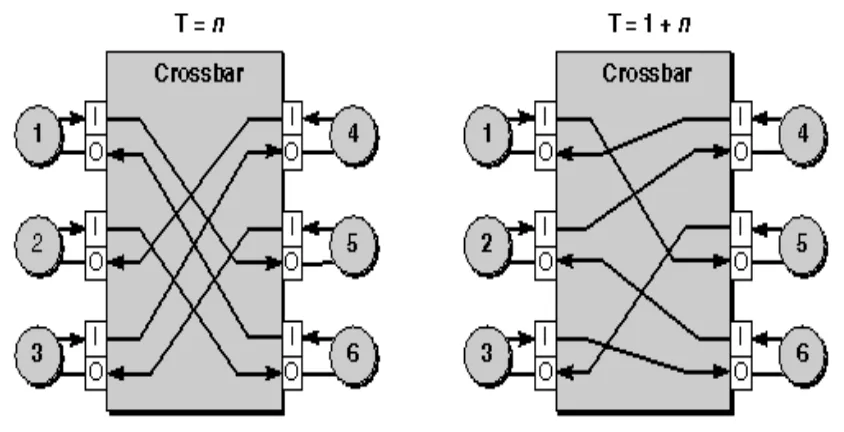
Figure 7: Block Diagram of Crossbar
Crossbar switches are commonly used in information processing applications such as telephony and circuit switching, but they are also used in applications such as mechanical sorting machines.
Let us assume that at clock T=n, the ports independently make the following parallel connections from 1-to-5, 2-to-6, 3-to-4, 4-to-2, 5-to-3, and 6-to-1. Figure 7 shows the source (Input) and target (Output) for each connection, and arrows indicate the direction of flow. When a connection is active, its source and target are not available for any other connection over the crossbar.
At the next clock, T=n+1, the ports independently reconfigure themselves into six new data links: 1-to-5, 2-to-4, 3-to-6, 4-to-1, 5-to-3 and 6-to-2. At clock intervals, the ports continue making new connections as needed. Connection decisions are based on algorithms that take into account flow control, routing, and arbitration. 4.3 Router
Figure 8: Block Diagram of Router
The router has a control logic which describes the switching in the crossbar switch. The control logic has signals coming from the arbiter. the control logic can be a 3-bit as normally crossbar switch has five input ports that can be independently connected to any five output ports.
V.
TRAFFIC
PATTERNS
Traffic patterns describe the destination to which the packet is sent by which source. Some patterns describe a specific destination for a specific source. Few patterns describe a different destination to a specific source at a different time. [5] These patterns are thus used to create traffic in NoC. Few of these patterns are described below with dimension order routing (X-Y routing) algorithm.
5.1 Bit-Complement
Figure 9: Bit-Complement Traffic
Destination address = complement (Source address)
For source address 0000 the destination is 1111. If we consider dimension order routing algorithm with first X and then Y, then the movement of the packets is as shown in figure 9.
5.2 Bit-Reversal
Traffic pattern that is similar to the bit-complement is bit-reversal. The bit-reversal traffic pattern has a dedicated destination to particular source. The destination address can be calculated by changing the first bit as the last bit and second to bit before last bit and so on. That is MSB of the source will be LSB of destination and LSB of the source will be MSB of destination.
Destination address = bit reverse (Source)
Figure 10: Bit-Reversal Traffic
5.3 Transpose
Transpose traffic is another traffic pattern that is used in many network traffic simulations. This traffic pattern has a specified destination for all the sources. The source address is used to determine the destination address in above two patterns. Here the address of the destination is not calculated by its source address, instead the position of the source is used to define the address of its destination.
Destination address (Yth Row, Xth Column) = Source (Xth Row, Yth Column)
Every interface connected to a router in a network can be described by its position, as the network is considered to be dimensional. Every interface can be thus represented by using the coordinates, which is by its row and column numbers. For source having 0th row and 1st column. The destination will be 1st row and 0th Column. The direction of traffic with X-Y routing is as shown in figure 11.
Figure 11: Transpose Traffic
5.4 Tornado
Tornado traffic pattern is similar to the transpose traffic. In this traffic pattern, the destination address is obtained by the position of the source. The destination address is calculated by this formula.
Destination address = (K-1)/2 steps to right and (K-1)/2 steps above the source.
Figure 12: Tornado Traffic
5.5 Uniform
The traffic pattern that has different destination address to the same source at different time intervals is the uniform traffic. The traffic is uniform as any source can send packets to any destination. Figure 13, shows the source which is ready to send the packets of data. The destination is not shown as there is no fixed destination. The destination address will be generated by a random selection of address.
Figure 13: Uniform Traffic
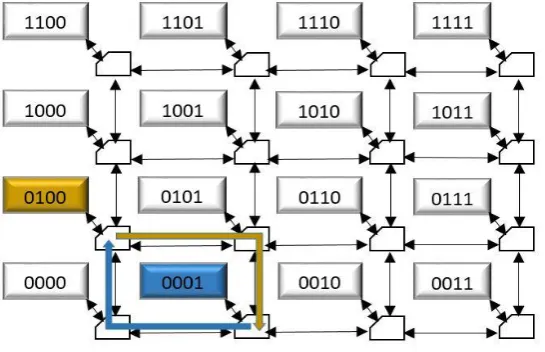
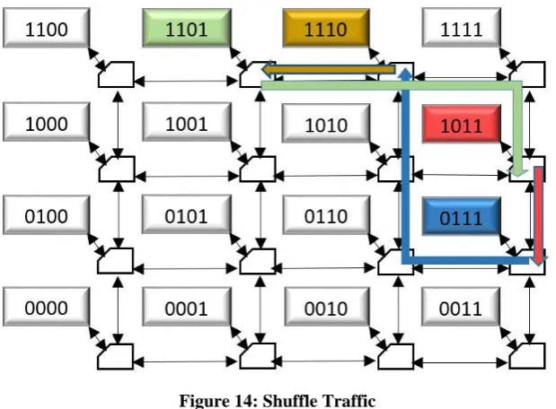
A unique traffic pattern that is used in network traffic analysis is the shuffle traffic. Shuffle traffic is not one source to one destination traffic pattern. The shuffle as the name has a shuffled traffic. That is, the traffic pattern is a set of address and destination address is left a circular rotation of its source address. For a 4X4 network shuffle traffic is a set of four address as the minimum bit required to represent these address is 4 bits.
Destination address = Left circular shift (Source address)
Figure 14: Shuffle Traffic
Let us assume a starting address as 0111 now this will have a destination as 1110. 1110 will have a destination as 1101 and this will have a destination as 1011. The movement of the traffic with X-Y routing algorithm for shuffle traffic is shown in figure 14.
VI.
CONCLUSION
A Network on Chip is one of the important block in many multi-core systems. Designing and implementation of NoC’s are very important as they describe system performance. Throughput and latency are the important parameters that describe the quality of the NoC. This paper gives an overview of traditional bus based architecture and its disadvantages. NoC’s offer much less delay by providing multiple paths to communicate. Arbiter and Router are the important blocks of NoC. Dimension order Routing is considered with X-Y routing algorithm and this algorithm is used to define paths in the traffic patterns.
REFERENCES
[1] Cheng Li and Paul Ampadu, “Energy-Efficient NoC with Variable Channel Width,” IEEE 58th International Midwest Symposium on Circuits and Systems (MWSCAS), 2015.
[5] N. Jiang et al., “A detailed and flexible cycle-accurate network-on-chip simulator”, IEEE International Symposium on Performance Analysis of Systems and Software (ISPASS), 2013, pp. 86–96.
[6] Skeie, T. Sem-Jacobsen, F.O. Rodrigo, S. Flich, J. Bertozzi, D. Medardoni, S., “Flexible DOR routing for virtualization of multicore chips,” System-on-Chip, 2009. SOC 2009. International Symposium
[7] H. Kim, B. Grot, P. Y. Gratz, and D. A. Jimenez, "Spatial Locality Speculation to Reduce Energy in Chip-Multiprocessor Networks-on chip," IEEE Transactions on Computers, vol. 63, no. 3, pp. 543-556, 2014. [8] Suyog K. Dahule, Pallavi D. Tiware, Sagar Soitkar, “Review on Network on Chip (NoC) Topology,”
IJIRCCE Vol. 4, Issue 5, May 2016 ISSN (Online): 2320-9801, ISSN (Print): 2320-9798
[9] Y. Jin, K. H. Yum, and E. J. Kim, "Adaptive data compression for high-performance low-power on-chip networks," in Proceedings of the 41st annual lEEElACM International Symposium on Microarchitecture. IEEE Computer Society, 2008, pp. 354-363.