Pilot Extraction for CFO Estimation using Comb-Type
Pilot Arrangement
Piyush Yadav
M. E. Student
Dept. of Electronic & Comm. Engineering M.I.T.M. Indore, India
Ratna Gour
Sr. Assistant Professor
Dept. of Electronic & Comm. Engineering M.I.T.M. Indore, India
ABSTRACT
Frequency synchronization is vital issue in execution of OFDM system. In this paper we proposed a technique to estimate and compensate CFO in frequency domain. Estimation is based on Comb-type pilot sequence, which can measure phase rotation of received signal pass through fading channel. Performance of proposed scheme is evaluated on basis of MSE and BER. CFO estimation can be computed by pilot, phase information obtained at receiver side. It is estimated at receiver by fine CFO estimation.
Keywords
Carrier Frequency Offset (CFO), Pilot subcarrier, Digital Video Broadcast – Terminal, Mean Square Error (MSE), Bit Error Rate (BER).
1.
INTRODUCTION
In modern communication systems, Orthogonal Frequency Division Multiplexing (OFDM) transmission systems with high bit rate and high bandwidth utilization are frequently used. In OFDM single data stream is divided into parallel data stream and transmitted over different subcarriers. Orthogonality can be achieved by separating carrier by assigning integer multiples [1]. OFDM is used in WLAN, WiMAX, DVB-T, 4G and DAB system of wireless communication standards [2]. The OFDM technique has lots of advantage such as robustness against frequency selectivity, bandwidth efficiency, multipath fading channel, and simple equalizer designing. Besides these advantages, it has critical issue such as frequency and time synchronization. To achieve orthogonality a system should be very accurate in term of synchronization. If it is not accurate, Inter Carrier Interference (ICI) and Inter Symbol Interference (ISI) will occur which degrade system performance. Carrier Frequency offset arises due to frequency difference in the local oscillator of the transmitter and the receiver [3].
Many synchronization algorithms in literatures are proposed in recent years to estimate Carrier frequency offset (CFO) for single input and single output (SISO) and multiple input and multiple output (MIMO) OFDM system. CFO estimation can performed either in time domain or frequency domain. In time domain cyclic prefix (CP) and training sequence can be used to estimate CFO. Here CFO can be found from phase angle of product of CP and rear part of OFDM symbol. CFO determined by training symbol cover wider range than CP based estimation method. Here training symbols are repetitive with shorter period, but it has a drawback as we increases range of estimation it may increases Mean square error.
Frequency domain technique compare phase shift of subcarriers which occurs due to carrier frequency offset. Pilot based estimation method is suitable to find carrier frequency offset with the help of either comb like pattern or block type
pattern. Pilot is basically a reference signal that provides channel state information. Pilot structure of comb pattern [4] is preferable to block type pilot arrangement. Comb-Type pattern pilots are inserted in frequency domain with each OFDM symbol for CFO tracking .Normalized CFO divided into two parts which are integral CFO (IFO) Ɛi and fractional CFO Ɛf
(FFO) [5]. IFO doesn’t affect the orthogonality but FFO destroy orthogonality.
In this paper we have extracted pilots spread in subcarrier in regular interval and estimating CFO by performing fine CFO estimation. Simulation result shows Mean square error with signal to noise ratio (SNR) in dB.
2.
SYSTEM MODEL
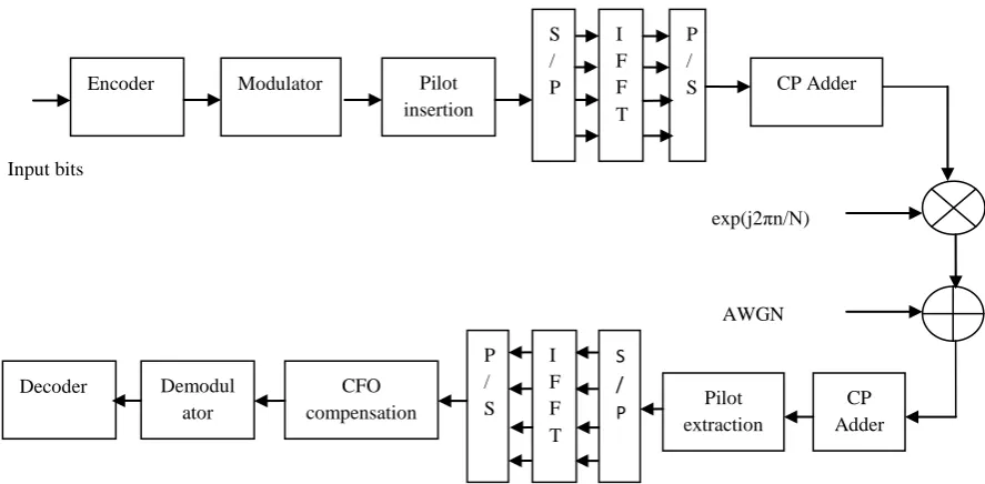
Consider an OFDM system shown in fig.1, the data source emits symbol which belongs to M-PSK, 16-QAM, or 64-QAM and are assumed to be independent and equiprobable. The symbolic sequence is serial to parallel converted into block of N symbols.
OFDM signal in Continuous time domain.
Cyclic prefix is to extend OFDM signal by copying last sample of OFDM symbol into its front. TG is the length of cyclic prefix.
Where
Effect of channel on received baseband symbol considering the effect of channel noise at receiver.
denote kth subcarrier frequency component of lth transmitted symbol, channel frequency
response & noise in frequency domain.
Fig 1: Block diagram of OFDM Transmitter and Receiver
3.
PILOT STRUCTURE
IEEE 802.11n is the latest standard used in mobile technology which is a part of 802.11 families. The standard define physical layer that can use 64 or 128 subcarriers with oscillator frequency of 2.5 or 5 GHz. Also 802.11n allocate boosted pilot subcarrier as shown in fig.2. LTE (Long Term Evolution) is a part of 4th generation technology which belongs to third Generation Project Partnership (3GPP) and Universal Mobile Telecommunication Systems (UMTS) and to cope with next generation communication requirement [6]. Packet oriented network LTE and DVB-T/H doesn’t include a preamble to provide frequency synchronization. Instead boosted pilots are inserted in frame to cope up with CFO problem. Continual pilot subcarriers are introduced in 802.11n, 802.16d and DVB-T/H but LTE only include pilot subcarriers at some regular symbols. Suppose a mobile is moving with speed of 120km/h at frequency of 2.5 GHz and subcarrier spacing in LTE is 15 KHz; thus, normalized CFO will be 0.0185. CFO have inverse relationship with carrier spacing as it decreases normalized CFO increases.
Consider comb-type pilot arrangement, in which every OFDM symbols are allotted pilot tones at some specific period, which is used as frequency interpolation to estimate CFO.
Fig 2: Comb-Type pilot
4.
CFO ESTIMATION & ALGORITHM
Received signal is multiplied by a carrier signal for the purpose of frequency up-conversion. At the receiver section, there is a need of frequency down conversion. But since these signals are generated by local oscillators which are seldom synchronized at both end transmitter and receiver. It may cause carrier frequency offset, which degrades signal quality and can affect orthogonality of subcarriers.Effect of carrier frequency offset (CFO) on received can be modeled as a time variant phase shift
, the received OFDM signal can be written as
CFO arises due to frequency offset. Let denote carrier frequency in transmitter and receiver and difference denoted by .
Where CFO , Δf is subcarrier spacing
Doppler frequency is calculated by , where C denotes speed of light.
Recall that the normalized CFO can be divided into two parts integer CFO (IFO) Ɛi and fractional CFO (FFO) Ɛf. The
normalized CFO will be . Effect of integer CFO (IFO) is as follows –
When we transmit sample it experience IFO i.e. Ɛi. It
degrades BER performance but it doesn’t affect orthogonality. IFO cause cyclic shift in transmitted signal, and received signal will be .
RX Effect of fractional CFO (FFO) is as follows -
Taking FFT of in frequency domain received signal with Ɛf (FFO).
Where,
Time
Boosted Pilot
Carrier Frequency
Data subcarrier
Encoder Modulator Pilot
insertion
S / P
I F F T
P /
S CP Adder
CP Adder Pilot
extraction S
/ P I
F F T P / S CFO
compensation Demodul
ator Decoder
exp(j2πn/N)
[image:2.595.61.279.583.715.2]
Where represent amplitude and phase distortion of kth subcarrier due to FFO. When FFO increases amplitude and phase distortion becomes severe and orthogonality among subcarrier isn’t maintained.
In this section, we are discussing various CFO estimation schemes in brief.
4.1 Time-Domain Estimation
4.1.1 Cyclic Prefix method
Here, results in a phase rotation of in the received signal. Under the assumption of negligible channel effect, the phase difference between CP and the corresponding rear part of an OFDM symbol caused by CFO is . CFO can be found from the phase angle of the product of CP and the corresponding rear part of an OFDM symbol.
To reduce the noise effect average can be taken over the samples of cyclic prefix.
Argument operation is performed by using , the range of CFO estimation is . becomes real only when there is no frequency offset.
Imaginary part of is used as CFO estimation. In this case estimation error is defined as
Where, L is number of samples used for averaging.
Frequency synchronization can be maintained by controlling VCO in accordance with sine function .
4.1.2 Training Symbols
Two identical symbols are transmitted consecutively, corresponding signal with CFO of Ɛ are related each other.
Although the range of CFO estimated is , it can be increased D times by using training symbol with D repetitive pattern. Note that this particular CFO estimation technique requires a special period, usually known as a preamble period, in which the consecutive training symbols are provided for facilitating the computation. The estimation range of CFO can be increased by reducing the distance between two blocks of samples for correlation. This is feasible by using training symbols that are repetitive with some shorter period.
Let a transmitter send the training symbols with D repetitive patterns in the time domain, which can be generated by taking
the IFFT of a comb-type pilot arrangement in the frequency domain.
If and are identical, a receiver can make CFO estimation as
As D increases, CFO estimation range is also increases but it may degrade performance of MSE (Mean Square Error).By taking average of estimate with repetitive pattern, we increases range of CFO without sacrifice of MSE.
4.2 Frequency-Domain estimation
Moose [7] gives the MLSE (Maximum likelihood sequence estimator) for carrier frequency offset estimation. The limit of acquisition range for the carrier frequency is .
Classen [8] proposed a technique in which pilot can be inserted and transmit in OFDM symbol for CFO estimation.
First two OFDM symbol saved in memory after synchronization.
Here fine CFO is estimated by IFO,
5.
PROPOSED ESTIMATION SCHEME
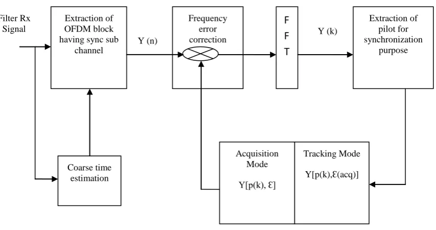
Pilots can be inserted in frequency domain and transmit in each OFDM symbols for CFO tracking. Pilot has been designed to minimize MSE, improve channel capacity, channel estimation and minimizing symbol error rate. One OFDM symbol is transmitted instead of two symbols , then, the signals are transformed into
via FFT. After estimating CFO
from pilot tones in the frequency domain, the signal is compensated with the estimated CFO in the time domain as shown in fig. 3. In this process, two different estimation modes for CFO estimation are implemented: acquisition and tracking modes.
Acquisition mode benefited by aid of pilots subcarriers, which are known at receiver.CFO acquisition can be divide into two steps, the integer part (IFO) and fractional part (FFO). In the acquisition mode, a large range of CFO including an integer CFO is estimated. In the tracking mode, only fine CFO is estimation.
Where L is number of subcarriers, p(k) is location of kth pilot tone,
Fig 3: Block diagram of Proposed CFO Synchronization scheme using pilot tone.
is the pilot tone located at p(k) in frequency domain at lth symbol period in transmitted signal.
Proposed Scheme works at CFO range .
6.
SIMULATION RESULT
An OFDM system with 16-QAM modulation, 128 subcarriers and a CP of 32 samples is considered here for comparison of the performances in term of MSE and BER.
Proposed scheme contain pilots at four spaces apart . All pilot signals are boosted by some extent or signal power used is optimal, so it doesn’t cost high in terms of power as shown in Table 1.
Table 1. Transmitted pilot with data
Boosted pilots
Transmitted data subcarriers
1.0 3.0 - 1.0i 3.0 - 1.0i 3.0 + 3.0i
1.0 3.0 + 1.0i -1.0 + 3.0i 1.0 + 3.0i
1.0 1.0 + 3.0i -1.0 - 1.0i -3.0 + 1.0i
1.0 3.0- 3.0i -1.0- 1.0i -1.0 + 3.0i
[image:4.595.94.521.75.300.2]Table 2 is showing received signal, pilots arranged in comb-type extracted at receiver to track CFO. Extracted pilot is sent for the CFO estimation as eq.15 implies. With the help of fine CFO estimation we determined the maximum angle obtained by received pilot multiplied with original pilot signal. Phase shift of signal is within the range of 2π and estimated easily with the help of eq.16.
Table 2. Received pilot with data
Received pilots
Received data subcarriers
-0.417- 0.067i -2.328+ 0.436i
4.484- 0.986i
0.502 - 0.636i
0.280+ 0.380i 1.477+ 1.503i
-0.330- 2.917i
-0.035- 2.046i 0.448 - 0.356i -0.544-
4.579i
-0.364- 4.411i
1.675- 1.631i 0.877+ 1.636i 1.173-
0.243i
1.611- 1.021i
-2.568 +0.363i
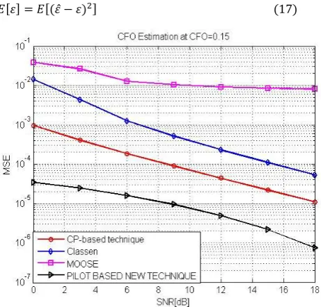
We compare MSE performance with Moose, Classen and CP based method. Moose technique requires a special preamble period and estimation range of CFO is . This method is based on MLSE (Maximum Likelihood Sequence Estimator). CP method estimate CFO by extending length of OFDM symbol . Classen introduce a scheme uses trial and error method to find CFO which is computationally complex [8].
Proposed scheme uses a boosted pilot subcarrier arrives at receiver. Receiver first acquired signal and extract pilot subcarrier. CFO is estimated in two parts IFO and FFO. This technique has computationally less complex and performs well compare to others. Compensated CFO signal is shown by BER graphs. After estimating CFO, it compensates by compensation circuit and we find that it gives good BER performance described in section 6.2.
6.1
Mean Square Error Performance
A Rayleigh channel consisting of five paths is considered. Channel is estimated at receiver and it is corrected by equalization. OFDM frames are simulated considering system with 128 point FFT and pilot spacing is four. CP consists of rear Extraction of
OFDM block having sync sub
channel
Frequency error correction
F
F
T
Extraction of pilot for synchronization
purpose
Tracking Mode Y[p(k),Ɛ(acq)] Acquisition
Mode Y[p(k), Ɛ] Coarse time
estimation Filter Rx
Signal
Y (n)
[image:4.595.304.540.346.519.2]samples. Convolution code is suitable for synchronization to provide optimal performance. Repetitive pattern D=1 is taken for simulation, as the value D increases, CFO estimation range can be increased but it may degrades the performance of MSE. CFO is calculated for and at different values of SNR as shown in fig 4 and fig 5
.
[image:5.595.56.287.147.368.2]
Fig 4: Simulation with CFO=0.15
[image:5.595.312.547.284.736.2]Estimation performance is based on MSE vs. SNR in dB.MSE will be calculated with the help of eq. 16. Moose method based on two consecutive symbols during preamble and method fails to estimate accurate frequency offset. It is applicable in the duration of preamble period when symbol cannot be transmitted. Classen method extracted pilots at frequency domain, it estimate CFO accurately but fails when CFO values goes higher. This method can compute CFO accurately when repetitive pattern D increases. Cyclic prefix is a classical approach to estimate CFO, it estimate CFO by averaging number of samples.
Fig 5: Simulation with CFO=0.4
As CFO increases, MSE performance may degrade as shown in fig 5. Estimation range of proposed scheme is . If
exceed to estimation range, it will not possible to estimate CFO accurately. Fig 5 shows that Classen method is lagging behind other methods means if CFO value increases, repetition of symbol will not perform good estimation. In this case pilot based proposed scheme is good in terms of MSE.
6.2
BER Performance
In this section, the MATLAB simulation is performed to evaluate BER performance. The simulation parameters are as follows: there are 128 subcarriers including 32 pilots, which are four spacing apart with each other, Convolution coding is done at rate of ½. At Decoder side hard decision decoding is performed. Convolution code is suitable for synchronization to provide optimal performance. Modulation scheme used 16-QAM; fading channel is Rayleigh fading channel with additive white Gaussian noise, all SNR values are in dB. Normalized Carrier frequency offset value for which BER calculated is
[image:5.595.316.546.294.501.2]and .
Fig 6: BER result when CFO=0.15
[image:5.595.59.289.531.722.2]BER performance shown in fig 6, when CFO is inserted in OFDM frame, BER performance get degrades. It is due to fact that IFO affects BER. Integer frequency offset (IFO) introduce bit errors. IFO shift transmit signal by cyclic shift and, therefore it is necessary to compute IFO accurately. As CFO increases BER get increases as shown in fig.5.9 because more cyclic shift is introduced in OFDM symbols. To compensate CFO estimated value of CFO multiplied in time-domain with the help of eq.24.
Where is Compensated signal in Time-domain.
7.
CONCLUSION
In this paper CFO problem is studied and a method has been presented based on comb type pilot arrangement to estimate CFO. Proposed algorithm work on frequency domain and estimated CFO is compensated in time domain. It also characterized by low computational complexity.The simulation result show the good performance of our proposed pilot assisted scheme.MSE calculate performance of proposed scheme which is superior to CP based, Moose and Classen method. Advantage of this method is that there is no need of repeating sequence to estimate CFO. BER result shows that compensated OFDM symbol improves BER performance at different values of SNR (dB).
In this work we investigated carrier frequency offset problem and frequency synchronization in frequency domain for OFDM system based on pilot assisted scheme using comb-type pilot arrangement. More research still needed in Frequency synchronization and it is very essential for any wireless transmission. Future work can be done to increase range of estimation and estimation accuracy.
8.
REFERENCES
[1] W. Y. Zou, Y. Wu, “COFDM: an overview,” IEEE Transaction on Broadcasting, vol.41, no.1, pp.1-8, mar.1995.
[2] European Telecommunication Standard ETS 300 744, “Digital broadcasting system for television, sound and data services; Framing structure, channel coding and modulation for digital terrestrial television,” 1996. [3] J.-J. Van de Beek, M. Sandell, and P. O. Borjesson, “Ml
estimation of time and frequency offset in OFDM systems,” IEEE Trans. Signal Process., vol. 45, no. 7, pp. 1800–1805, Jul. 1997
.
[4] Hsieh, M. and Wei, C. (1998) Channel estimation for OFDM systems based on comb-type pilot arrangement in frequency selective fading channels. IEEE Trans. Consumer Electron., 44(1), 217–228.
[5] Y. S. Cho, J. Kim, W. Y. Yang and C. G. Kang, MIMO-OFDM wireless communication with MATLAB, 1st ed. John Wiley and Sons (Asia) Pte Ltd, 2010.
[6] J. Gonzalez-Bayon, C. Carreras, and A. Fernandez-Herrero, “Comparative evaluation of carrier frequency offset tracking scheme for WiMAX OFDM system,” in proceedings of the IEEE Symposium on Signal Processing and Information Technology (ISSPIT’07), Cairo, Egypt, December 2007.
[7] P. Moose, “A technique for orthogonal frequency division multiplexing frequency offset correction,” IEEE Trans. Commun., vol. 42, pp.2908–2914, Oct. 1994.