http://dx.doi.org/10.4236/ojapr.2014.22003
Improvement in Reflectarray Antenna
Bandwidth with Changing the Geometrical
Shape
Alireza Bayat, Vahid Soufi Niyaraki
Department of Communication, Imam Khomeini International University, Qazvin, Iran Email: [email protected], [email protected]
Received 13 April 2014; revised 21 May 2014; accepted 13 June 2014
Copyright © 2014 by authors and Scientific Research Publishing Inc.
This work is licensed under the Creative Commons Attribution International License (CC BY). http://creativecommons.org/licenses/by/4.0/
Abstract
The method of this paper is based on change in the geometrical shape of the reflectarray plane which is similar to a concave shape and with this changing, it is tried to make the incident waves orthogonal as much as possible in order to remove the phase error caused by incident wave varia- tion. The other benefit of this work is omitting frequency change error caused by path difference between reflectarray antenna bandwidth. Two types of reflectarray antennas operating at X-band frequency with a linear polarization are considered in this design: concave and flat reflectarray antennas with the diameter of 135 mm. elements which are used in this paper are variable-size patches. The proposed reflectarray antenna (concave) approximately has 25% 3-dB bandwidth which shows an increment in bandwidth about 18% compared to flat reflectarray antenna.
Keywords
Increasing of Reflectarray Antenna Bandwidth, Non-Flat Reflectarray Antenna
1. Introduction
Design and analysis of reflectarray antennas is based on reflection phase versus elements size. In this method it is supposed that the phase response is independent of incident field, this technique is valid for those elements which are located in the center of the reflectarray plane and with a center-fed situation. The technique of ortho-gonal incident field can have suitable estimation for reflectarray antennas with center-fed when an enormous amount of reflection fields reflected from the center region of the antenna. For variable size patches with 40˚ in-cident wave, phase will change about 25˚ beside the orthogonal incident wave. When the incident wave is about 60˚, this variation in phase reaches to 50˚ [8]. Therefore, this technique is not suitable for the elements near the edges of the reflectarray and a new technique is needed. The technique which is used in this paper is based on making the ground plane in form of a concave in order to cause the incident waves become orthogonal to the patches and also reducing the frequency change error for increasing the bandwidth.
2. Design of the Non-Flat Reflectarray Antenna (Concave)
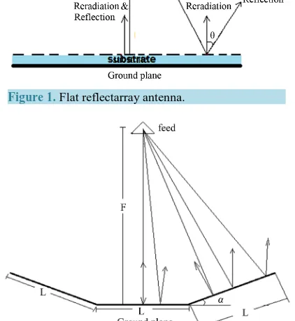
Beside the reflection waves from the reflectarray patches, specular reflection is also considered. Two specular reflections occur from reflectarray plane: reflection from the ground plane and reflection from the resonating patches. Because of the reflection from the resonating patches are negligible, only the reflection from the ground plane of the reflectarray is considered. Specular reflections from the ground plane in the regions near to the cen-ter of the reflectarray are approximately in the direction of reradiated waves but as the becomes bigger, specular reflections more apart from the reradiation waves and it causes increase in side lobes in radiation pattern of the antenna (Figure 1). Figure 2 indicates the new structure of the ground plane which has a concave shape.
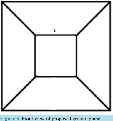
[image:2.595.201.398.392.535.2]For the first part of design a suitable degree (α) is required in which the maximum of reflection waves are si-tuated in the main beam direction. In this design, the reflectarray shape is considered as a square in which each side is 135 mm. as can be seen in Figure 3, the ground plane of the reflectarray is divided in two parts: center part and other corner parts in which the center part is a square which has L side and the corner parts with trape-zoid shape which are connected to the four sides of center part.
Figure 1. Flat reflectarray antenna.
[image:2.595.193.404.466.696.2]Figure 3. Front view of proposed ground plane.
The small side and altitude of the trapezoid are equaled to L. Also trapezoidal planes are located angular with the Z axis in which the angle between the normal (orthogonal) vector of trapezoidal planes and Z axis is α.
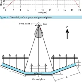
With considering the ground plane size (135 mm) and with considering f/D to 1, we locate the phase center of the horn antenna in the 135 mm distance from the center of concave plane and examine the directivity according to the variation in α degree. With considering Figure 4, with changing α from 0˚ to 20˚, it can be seen that the maximum directivity is in α = 10˚. Here, the maximum directivity indicates the maximum reflection waves in the main beam direction.
2.1. Reflectarray Elements Design
This part is based on situating dielectric layer on the ground plane and also designing patches on the dielectric. Because the ground plane shape of this antenna is not like the conventional reflectarrays, a suitable solution is needed. For calculation of phase difference for every patches in order to control main beam in
(
θ φb, b)
direc-tion, equation
φ
R(
x yi, i)
=k0di−(
xicosφ
b−yisinφ
b)
sinθ
b is useable but this equation is valid only for aflat reflectarray planes.
The main issue in this design is making all elements of the proposed reflectarray inphase. In flat reflectarray with using previous equation, we can make the elements of the center plane and trapezoidal planes inphase but the major problem is making these elements inphase together. This issue is illustrated in Figure 5.
2.2. Novel Formula for Calculating Elements Phase of a Non-Flat Reflectarray
In this section, a novel formula for making all elements of a non-flat reflectarray plane is presented. First of all, an important point exists in designing patches which is when a constant value
(
φ =0 2nπ , n= ± ± ⋅⋅⋅0 , 1, 2 ,)
adds to the computing phase, inphase condition of the patches will keep [9]-[11]. Figure 6 verifies this point. In Figure 6, D,θb,x k0, 0 are antenna diameter, angle between antenna main beam and Z axis, constant value as shown in Figure 6, propagation constant, respectively.Based on these values, it can be concluded that φ0=k0
(
D+x0)
sinθb is constant because all parameters inthis formula have a constant value and also these parameters should be choose in order to make φ0 equals 2nπ in which n is integer as a result k0
(
D+x0)
sinθb=2nπ.As mentioned in previous sentence, with adding this constant (φ0) to
(
,)
0(
cos sin)
sinR x yi i k di xi b yi b b
φ
= −φ
−φ
θ
, inphase situation of element will keep. If we assume φ =b 0, equations of this examination are presented below:(
,)
0 sin( )
0, 0 2 π, 0 , 1, 2 ,R x yi i k di xi b n n
φ
= − ×θ
+φ
φ
= = ± ± ⋅⋅⋅ (1)(
,)
0 sin( )
0(
0) ( )
sinR x yi i k di xi b k D x b
Figure 4. Directivity of the proposed ground plane.
Figure 5. The antenna which is designed by conventional formula.
Figure 6. The reflectarray coordination and virtual plane.
(
,)
0 sin( )
0sin( )
sin( )
R x yi i k di xi b x b D bφ
= −θ
+θ
+θ
(3)(
,)
0( )
0(
0) ( )
sinR x yi i k di k D x xi b
φ = + + − θ (4)
By substituting
(
D+x0−xi)
sinθ
b with di′, the Equation (4) will become:(
,)
0(
)
R x yi i k di d i
[image:4.595.156.445.448.613.2]As can be seen in Figure 6, di is the elements distance from the horn phase center and di′ is the elements distance from the virtual plane in which the orthogonal vector of the virtual plane ids located in the main beam direction of the antenna. It should be noticed that the virtual plane should be parallel with the reradiation wave plane from the patches and also one side of the virtual plane should have connection with end of reflectarray plane (connection point in Figure 6).
2.3. Computation of Reflectarray Element Phase
In this section, we obtain (calculate) phase of elements which are located on the non-flat reflectarray by using the equation φR
(
x yi, i)
=k0(
di+di′)
. In order to use this technique firstly we should consider a suitable virtualplane. Considering that the maximum of specular reflections in the proposed antenna (Figure 4) is in the Z axis direction, the antenna main beam (caused by resonating patches) is also will design in that direction. As the main beam direction of the antenna of Figure 4 is in the Z axis direction, therefore, orthogonal vector of virtual plane should be paralleled with the Z axis.
Concerning Figure 7, we consider the virtual plane in a special height from the ground plane and also in front of it. In order to obtain the phase of each element, it is required to calculate di, di′ parameter for each ele-ment.
In this antenna, the variable sized patches are used. For computing elements phase, firstly size of each unit cell should be calculated. Here, size of each element (unit cell) is λ 2 and center frequency of this design is 10 GHz as a result of which each side of every unit cell is 15 mm. Dielectric constant which is used in this antenna equals to 2.2 (ε =r 2.2) and also dielectric height is 1 mm (h = 1 mm). Phase-element of microstrip patches with L side is shown in Figure 8.
2.4. Radiation Pattern and Bandwidth of Non-Flat Reflectarray
A horn antenna is used as feed in which the phase center distance from the reflectarray plane is 135 mm. Radia-tion pattern of the antenna are shown in Figure 9 and Figure 10.
Figure 7. Reradiation waves for designed reflectarray with pro- posed formula.
Figure 9.Radiation pattern of non-flat reflectarray antenna.
Figure 10. Two dimensional radiation pattern of non-flat reflectarray antenna in E-plane.
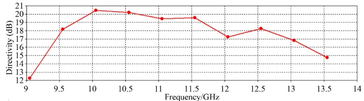
As can be seen in Figure 10, directivity of antenna in 10 GHz is about 19.2 dB. Figure 11 indicates the an-tenna directivity in the frequency range from 9 GHz to 14 GHz. −3 dB bandwidth obtained from this figure is about 25%.
3. Design of a Flat Reflectarray Antenna with the Same Scale of Non-Flat Proposed
Reflectarray in Order to Compare Their Bandwidth
In this design, ground plane has some condition of ground plane of Figure 2, with the difference in α which here equals to zero. With this value the antenna has the conventional shape as other reflectarrays. In other words, ground plane is a square with 135 mm side. Dielectric constant is same as non-flat reflectarray and also same thickness (ε =r 2.2 , h=1 mm).
Feed for this antenna is same as non-flat reflectarray which is a horn and have phase center distance from the ground plane which is radiation pattern of this antenna in center frequency of 10 GHz is shown in Figure 12. As can be seen in Figure 13, directivity of antenna in 10 GHz is about 21.6 dB. From Figure 10and Figure 13, it is considerable that the side lobe level of the proposed ground plane is lower than flat one which shows an im-provement in this parameter.
Figure 14 shows directivity of this antenna for frequency range from 9 GHz to 11 GHz. −3 dB bandwidth in center frequency is about 6.3%. As can be understood from the results, the non-flat reflectarray has increment in bandwidth about 18%.
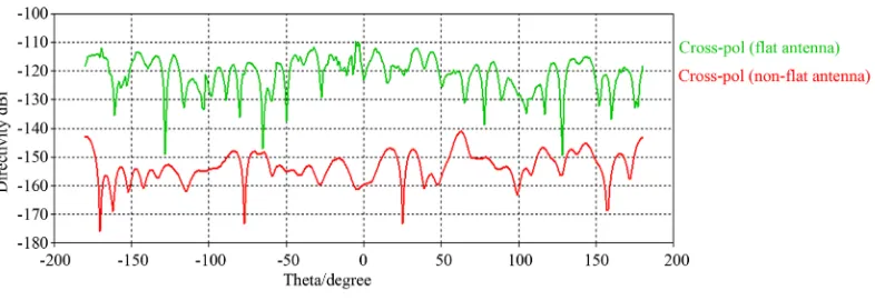
Another important parameter in antenna is cross-polarization which should be decreased in design. Radiation pattern with cross-polarization for non-flat and flat reflectarray antenna are shown in Figure 15. By considering the Figure 15, an improvement in cross-polarization for non-flat reflectarray exists.
4. Conclusion
Figure 11. Frequency response of non-flat reflectarray antenna with the diameter of 135 mm.
[image:7.595.113.489.555.659.2]Figure 12. Radiation pattern of flat reflectarray antenna.
Figure 13. Two dimensional radiation pattern of flat reflectarray antenna in E-plane.
Figure 14. Frequency response of flat reflectarray antenna with the diameter of 135 mm.
Figure 15. Cross polarization for flat and non-flat reflectarray antennas in center frequency of 10 GH.
Obtained bandwidth for a non-flat reflectarray (proposed antenna) with 135 mm diameter is about 25% which has improvement about 18% compared to flat reflectarray with same size.
References
[1] Huang, J. and Encinar, J.A. (2008) Reflectarray Antennas, IEEE/John Wiley & Sons, New York, 2008.
[2] Legay, H., Bresciani, D., Girard, E., Chiniard, R., Labiole, E., Vendier, O. and Caille, G. (2009) Recent Developments on Reflectarray Antennas at Thales Alenia Space. Proceedings of EuCAP, Berlin.
[3] Roederer (2009) Reflectarray Antennas. Proceedings of EuCAP, Berlin.
[4] Huang, J. (1991) Microstrip Reflectarray. IEEE AP-S/URSI Symposium, London, June 1991, 612-615.
[5] Pozar, D.M. and Metzler, T.A. (1993) Analysis of a Reflectarray Antenna Using Microstrip Patches of Variable Size. Electronics Letters, 657-658. http://dx.doi.org/10.1049/el:19930440
[6] Huang, J. and Pogorzelski, R.J. (1998) A Ka-Band Microstrip Reflectarray with Elements Having Variable Rotation Angles. IEEE Transactions on Antennas Propagation, 46, 650-656. http://dx.doi.org/10.1109/8.668907
[7] Sarah, A. and Hany, H. (2013) A Novel Microstrip Rotating Cell for CP-Reflectarray Applications. 2013 IEEE Radio and Wireless Symposium (RWS),20-23 January 2013, 121-123.
[8] Roederer, A. (2002) US6411255 “Reflector Antenna Comprising a Plurality of Panels”.
[9] Pham, K.T., Nguyen, B.D., Van-Su Tran, Bui, L.-P.P., Linh, M., Yonemoto, N., Kohmura, A. and Futatsumori, S. (2013) Ku Band Aperture-Coupled C-Patch Reflectarray Element Using Phase Shifting Line Technique. 2013 International Conference on Advanced Technologies for Communications (ATC),465-468.
[10] Li, L., Chen, Q., Yuan, Q.W., Sawaya, K., Maruyama, T., Furuno, T. and Uebayashi, S. (2011) Frequency Selective Reflectarray Using Crossed-Dipole Elements with Square Loops for Wireless Communication Applications. IEEE Transactions on Antennas and Propagation, 59, 89-99.
currently publishing more than 200 open access, online, peer-reviewed journals covering a wide range of academic disciplines. SCIRP serves the worldwide academic communities and contributes to the progress and application of science with its publication.
Other selected journals from SCIRP are listed as below. Submit your manuscript to us via either