http://dx.doi.org/10.4236/ijmnta.2016.51001
Advanced Control of a PMSG
Wind Turbine
Hafsi Slah, Dhaoui Mehdi, Sbita Lassaad
National Engineering School of Gabes, Photovoltaic, Wind and Geothermal Systems Research, Gabes, Tunisia
Received 4 July 2015; accepted 28 February 2016; published 2 March 2016
Copyright © 2016 by authors and Scientific Research Publishing Inc.
This work is licensed under the Creative Commons Attribution International License (CC BY).
http://creativecommons.org/licenses/by/4.0/
Abstract
In this work, an intelligent artificial control of a variable speed wind turbine (PMSG) is proposed. First, a mathematical model of turbine written at variable speed is established to investigate si-mulations results. In order to optimize energy production from wind, a pitch angle and DC bus control law is synthesized using PI controllers. Then, an intelligent artificial control such as fuzzy logic and artificial neural network control is applied. Its simulated performances are then com-pared to those of a classical PI controller. Results obtained in MATLAB/Simulink environment show that the fuzzy and the neuro control is more robust and has superior dynamic performance and hence is found to be a suitable replacement of the conventional PI controller for the high per-formance drive applications.
Keywords
Wind Turbine, Variable Speed, Pitch Angle, Pi Controller, Fuzzy Logic Controller, Neural Networks Controller
1. Introduction
Nowadays, among the all renewable energy sources, wind systems are more economic in comparison with oth-ers. Variable wind speed systems deliver 20% to 30% more energy in comparison with constant speed systems
[1]. Many developed generation systems are used to extract maximum wind energy. Optimum wind energy ex-traction system is achieved by running wind turbine generator in a variable speed mode because of the higher energy gain and reduced stresses [2].
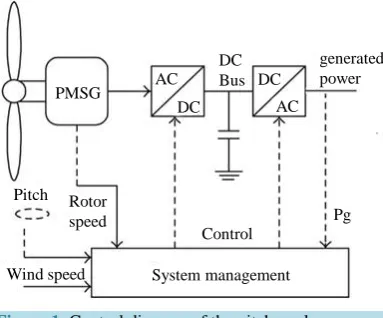
Figure 1. Control diagram of the pitch angle.
2. Wind Turbine Model
Wind turbine converts wind energy into mechanical energy. For a variable-speed, mechanical power available at the output of the wind turbine could be expressed by:
(
)
3 1 , . 2 m pP = ⋅ ⋅ ⋅ ⋅ρ S v C λ β (1)
Here, ρ is the air density, S = π∙R2 is the blades swept of the turbine, V is wind speed, and CP(λ,β) is the pow-er coefficient, which expresses the relationship between the tip speed ratio λ and the pitch angle β.
The mechanical power captured by the wind turbine is obtained as:
(
)
3 , 2
1 . 2 P m C
C ρ π R β λ v
λ
= ⋅ ⋅ ⋅ ⋅ ⋅ (2)
The power coefficient CP(β,λ) is a nonlinear function of the tip speed ration λ and the pitch angle β given by:
(
)
116 21, 0.5176 0.4 5 e i 0.0068 i
P
C λ β β λ λ
λ
−
= − ⋅ − + ⋅
(3)
where:
3
1 1 0.035
. 0.008 1 i
λ =λ+ ⋅β − +β
The relationship between the wind speed and the rotor speed is defined as tip speed ratio λ:
m
R
v
λ= ⋅Ω (4)
where Ωm is the blades angular velocity and R is the rotor radius. The developed turbine torque is:
. m m m P C =
Ω (5)
The relationship between the turbine power and turbine speed at maximum power output are given by:
5 3 max 3 max
1
.
2 opt p opt
P ρ π C R
λ
= ⋅ ⋅ ⋅ ⋅ ⋅Ω
⋅ (6)
2.1. Pitch Angle Control
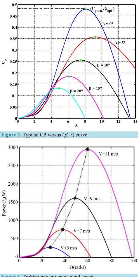
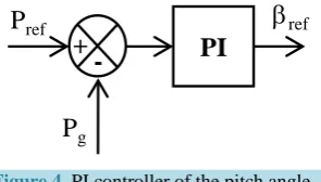
Wind turbines are generally designed to deliver maximum output at wind speeds around 15 m/s [3]. According to equation (1), for a given wind speed, the only parameter that allows to control extracted power is the Cp
rameter (Figure2). This parameter depends on the type of turbine and the type of design from the manufacturer. It is also a function of the pitch angle control, were mainly used to limit the mechanical power during strong wind speed or to adapt power production (Figure 3). The aerodynamic behavior of the wind turbine can be con-trolled actively by varying the turbine blade angle around their longitudinal axis [4].
In low and medium wind speed, the pitch angle control is rarely actuated and only set to the optimum value. In high wind speeds, the pitch angle control effects to regulate the extracted wind power so that the design limits of the turbine will not be exceeded. Rotor speed, torque or power control can be taken to regulate the pitch angle
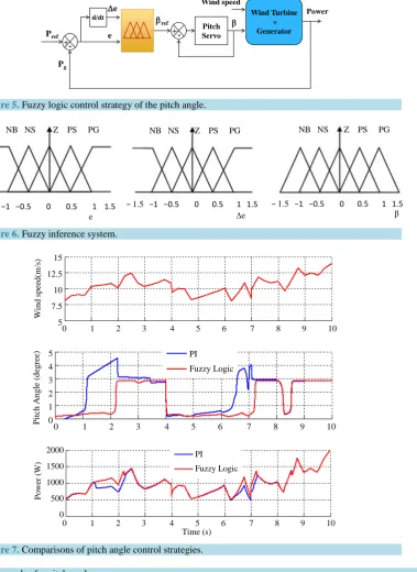
[5]. In this paper, the power error criteria are used. The error between the reference and the measured power at the output of the PMSG is sent to a PI controller to generate the reference value βref of the pitch angle [6].
2.2. PI Control for the Pitch Angle
The control system structure used to generate the pitch angle reference is depicted inFigure 4.
[image:3.595.194.432.244.717.2]Figure 2. Typical CP versus (β, λ) curve.
Figure 3. Turbine power versus wind speed.
V=11 m/s
V=9 m/s
V=7 m/s
V=5 m/s
Ω(rad/s)
0 20 40 60 80 100
P
o
we
r P
m
(W
)
3000
2500
2000
1500
1000
500
Figure 4. PI controller of the pitch angle.
The feed forward term assumes that all the components are ideal and does not account for the losses in the system. The feedback path compensates for the losses by decreasing the pitch angle, if the output power is less than the desired power, to increase the power captured.
2.3. Fuzzy Logic Control for the Pitch Angle
Fuzzy logic control is one of the most powerful control methods where based on fuzzy set theory and associated techniques. The fuzzy logic algorithm is suitable for wind turbine control with complex nonlinear models and parameters variation. The fuzzy controller (Figure 5) uses the perturbation and observation to track the optimal pitch angle without knowledge of wind turbine characteristic.
Basic structure of the fuzzy logic controller consists of three important stages: Fuzzification, Decision Making Unit and Defuzzification Unit. The inputs of the Fuzzification are selected as error and rate of change of error and the output is the pitch angle reference. The two input variables are calculated at every sampling instant say k [6].
( )
( )
( )
( ) (
1)
ref gs
e k P k P k
e k e k
e
T
= −
− −
∆ = (7)
where, Pref(k)and Pg(k)are respectively the reference and generated power at instant n.
In Fuzzification stage the crisp variables e(k) and ∆e(k) are converted into fuzzy variables which can be iden-tified by membership function (Figure 6). The proposed controller uses following linguistic labels cited in Ta-ble 1.
NB (Negative Big), NS (Negative Small), Z (Zero), PM (Positive Small), PB (Positive Big). The input and output variables map into the following fuzzy set (Figure 6).
The triangular membership functions are used to define both inputs (error, rate of change of error) and output (pitch angle).
2.4. Simulation Results
For evaluating the robustness of the fuzzy logic controller compared with the conventional PI controller at vari-able wind speed, the simulations (Figure 7) have been carried out using MATLAB/Simulink software.
Figure 7 shows the results of the conventional pitch angle control strategy where power is used as the con-trolling variable. The comparisons of different strategies show that proposed fuzzy logic control strategies is more robust in pitch angle control.
3. Model of the PMSG
The wind turbine drives a permanent magnet synchronous generator PMSG. By considering only the fundamen-tal harmonic of the flux distribution in the air-gap of the machine and by neglecting the homopolar component, the theory of the space vector gives the dynamic equations of the stator currents as follows:
.
. ds
ds s ds s s qs
qs
qs s qs s s ds f
di
v R i L p L i
dt di
v R i L p L i p
dt ϕ
= ⋅ + ⋅ − Ω ⋅ ⋅
= ⋅ + ⋅ + Ω ⋅ ⋅ + ⋅Ω ⋅
(8)
P
refP
g+
Figure 5. Fuzzy logic control strategy of the pitch angle.
[image:5.595.145.525.90.611.2]Figure 6. Fuzzy inference system.
[image:5.595.87.541.613.723.2]Figure 7. Comparisons of pitch angle control strategies.
Table 1. Inference rules for pitch angle. e
∆e NB NS Z PS PB
NB NB NB NS NS Z
NS NB NS NS Z PS
Z NB NS Z PS PS
PS NS Z PS PS PB
PB Z PS PS PB PB
Power Wind speed Wind Turbine + Generator β Pitch Servo +-βref
+-Pref e
∆e d/dt
Pg
− 1.5 −1 −0.5 0 0.5 1 1.5 − 1.5 −1 −0.5 0 0.5 1 1.5 − 1.5 −1 −0.5 0 0.5 1 1.5
e ∆e
NB NS Z PS PG
β NB NS Z PS PG
NB NS Z PS PG
0 1 2 3 4 5 6 7 8 9 10
W in d s p ee d (m /s ) 15 12.5 10 7.5 5 P it ch A n g le (d eg ree)
0 1 2 3 4 5 6 7 8 9 10 PI Fuzzy Logic 5 4 3 2 1 0
where Rs is the phase resistance of the stator winding, Ls is the stator cyclic inductance, Φfis the flux of the per-manent magnetic, vdsand vqs are the d-q components of the stator voltages respectively, ids and iqs are the d-q components of the stator currents respectively, and p is the number of pairs of poles.
The mechanical model of the PMSG wind turbine can be described by the simplified motion equation:
d d
e r m
T T J f
t
Ω
− = ⋅ + ⋅Ω (9)
where the electromagnetic torque is:
1.5 .
2
e f qs e qs
P
T = ⋅ ⋅ϕ ⋅i =k i⋅ (10)
4. DC Bus Control
The generator-side inverter is controlled to catch maximum power from available wind power. According to (10), in order to control the electromagnetic torque Te, this study just controls the q-axis current iqswith the as-sumption that the d-axis current ids is equal to zero. Furthermore, [7] [8] show that, in order to catch maximum power, the optimum value of the rotation speed is adjusted. The tip speed ratioλ is taken into account due to the equation being addressed as follow:
.
opt ref
V
R
λ ⋅
Ω = (11)
There, Ωref is the blade angular velocity reference and λopt is the tip speed ratio optimum.
4.1. Fuzzy Logic Controller for DC Bus
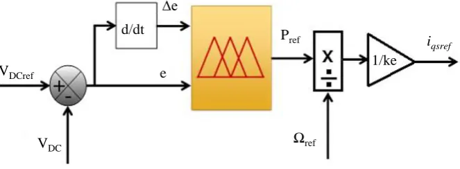
The fuzzy logic controller for the DC bus has three parameters (Figure 8). The first input is the error of DC vol-tage, the second is the rate of change of error and the output is the power controlling current component. The inputs variables are calculated at every sampling instant say k [9].
( )
( )
( )
( ) (
1)
DCref DCs
e k V k V k
e k e k
e
T
= −
− −
∆ = (12)
where, VDCref(k) and VDC(k) are respectively; the reference and measured voltage at instant n.
In Fuzzification stage the crisp variables e(k) and ∆e(k) are converted into fuzzy variables which can be iden-tified by membership function. The fuzzification maps the error and change in error to linguistic labels of fuzzy sets.
[image:6.595.149.481.584.706.2]The proposed controller uses following linguistic labels inTable 2: NB (Negative Big), NM (Negative Me-dium), NS (Negative Small), NVS (Negative Very Small), Z (Zero), PVS (Positive Very Small), PM (Positive Medium), PB (Positive Big).
Figure 8. Fuzzy DC bus controller.
VDC
VDCref
d/dt
e ∆e
Ωref
Pref i
qsref
4.2. Neural Network Controller for DC Bus
In this section a procedure for constructing a neural network model predictive controller for the voltage DC is presented. In practice, an operational load shedding scheme for bulk power systems should be able to incorpo-rate an infinite number of possible system states that would be mapped to a finite number of actions. The train-ing set should contain both the “standard” normal operational conditions and the state of parameters necessary to implement the appropriate action for system stability. Once the training process is completed, the benefits of the systems are immediately evident in the speed of response to faults and the seamless integration with existing power system controls. Load shedding neural networks are composed of an input layer, two hidden layers and one output layer. As mentioned earlier, using the model reference control tool in neural networks, it is possible to include a network control (Figure 9) with the transformer model to monitor the performance of the system [10].
The activation function of both the output layer are linear and unbiased while that of the hidden layer is sig-moid and biased.
Training the neural network is often done in epochs or cycles that are based largely on the inputs into the sys-tem. So for various inputs, the neural network basically compares each input to other known inputs and plots a graph of the error gradient between these two values. The process of comparison is carried out for as many random inputs as possible while each result and the corresponding response of the Plant are stored for future reference.
4.3. Simulation Results and Discussion
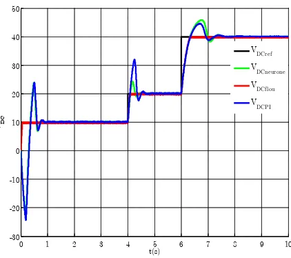
In order to evaluate the performance of the control system for the variable DC bus reference concept with PMSG, we set reference to 10 V. In the first next we shoes 20 V and finally we shoes 40 V.
Figures 10-12 show the responses of the system when using respectively IP, fuzzy logic and neural controllers. FromFigure 13, showing the comparison of the three responses; we note that the use of fuzzy provides a re-sponse with a smaller overshoot and faster compared to the neural controller and conventional IP controller.
Table 2. Rules table for DC bus. e
∆e NB NM NS Z PS PM PB
NB NB NB NB NB NS NP Z
NM NB NB NB NS NP Z PS
NS NB NB NS NP Z PS PM
EZ NB NS NP Z PS PM PB
PS NS NP Z PS PM PB PB
PM NP Z PS PM PB PB PB
PB Z PS PM PB PB PB PB
Figure 9. Neural network model.
∆e(k)
P
refP(k-1)
e(k)
Figure 10. DC voltage response with PI controller.
Figure 11. DC voltage response with fuzzy logic controller.
Figure 12. DC voltage with neural network controller.
0 1 2 3 4 5 6 7 8 9 10 0
10 20 30 40 50
t(s)
VD
C
VDCref VDC
0 1 2 3 4 5 6 7 8 9 10 -30
-20 -10 0 10 20 30 40 50
t(s)
VD
C
[image:8.595.202.424.517.704.2]Figure 13. Comparison between the deferent controllers.
5. Conclusions
This paper analyzes the control strategies as well as models and designs and simulates the whole autonomous system of PMSG wind turbine feeding AC power to the utility grid. In the first part of this work, we studied the control of the pitch angle. The proposed method is based on fuzzy logic and PI controller for tracking the optim-al pitch angle of wind turbine with a variable speed. The capability of the fuzzy logic controller is verified and it is found that it has a fast response than the conventional PI controller. In the second part, three techniques were tested: PI, fuzzy logic and neural networks to control the DC bus side generator.
The simulation results show that the combination of pitch angle controller and DC bus controller has good dynamic and static performance. The maximum power can be tracked and the generator wind turbine can be op-erated in high efficiency. DC-link voltage is kept at stable level for decoupling control of active and reactive power. Hence, the output will get the optimum power supply for the grid.
References
[1] Nguyen, H.M. and Naidu, D.S. (2011) Advanced Control Strategies for Wind Energy Systems. IEEE PES Power Sys-tems Conference & Exposition (PSCE), Phoenix, 20-23 March 2011, 1-8. http://dx.doi.org/10.1109/psce.2011.5772514
[2] Yin, M., Li, G., Zhou, M. and Zhao, C. (2007) Modeling of the Wind Turbine with a Permanent Magnet Synchronous Generator for Integration. IEEE Power Engineering Society General Meeting, Tampa, 24-28 June 2007, 1-6.
http://dx.doi.org/10.1109/pes.2007.385982
[3] Merabet, A., Thongam, J. and Gu, J. (2011) Torque and Pitch Angle Control for Variable Speed Wind Turbines in All Operating Regimes. 10th International Conference on Environment and Electrical Engineering (EEEIC), Rome, 8-11 May 2011, 1-5. http://dx.doi.org/10.1109/eeeic.2011.5874598
[4] Rolan, A., Luna, A., Vazquez, G., Aguilar, D. and Azevedo, G. (2009) Modeling of a Variable Speed Wind Turbine with a Permanent Magnet Synchronous Generator. IEEE International Symposium on Industrial Electronics (ISIE), Seoul, 5-8 July 2009, 734-739. http://dx.doi.org/10.1109/isie.2009.5218120
[5] Yao, X.J., Liu, Y.M., Xing, Z.X. and Zhang, C.M. (2008) Active Vibration Control Strategy Based on Expert PID Pitch Control of Variable Speed Wind Turbine. International Conference on Electrical Machines and Systems (ICEMS
2008), Wuhan, 17-20 October 2008, 635-639.
[6] Veeramani, C. and Mohan, G. (2011) A Fuzzy Based Pitch Angle Control for Variable Speed Wind Turbines. IEEE Student Conference on Research and Development (SCOReD), Cyberjaya, 36-39.
[7] Li, S., Haskew, T.A. and Xu, L. (2010) Conventional and Novel Control Designs for Direct Driven PMSG Wind Tur-bines. Electric Power Systems Research, 80, 328-338. http://dx.doi.org/10.1016/j.epsr.2009.09.016
[8] Chinchilla, M., Arnaltes, S. and Burgos, J.C. (2006) Control of Permanent-Magnet Generators Applied to Variable- Speed Wind Energy Systems Connected to the Grid. IEEE Transactions on Energy Conversion, 21, 130-135.
http://dx.doi.org/10.1109/TEC.2005.853735
[9] Chen, J., Wu, H.B., Sun, M., Jiang, W.N., Cai, L. and Guo, C.Y. (2012) Modeling and Simulation of Directly Driven
0 1 2 3 4 5 6 7 8 9 10 -30
-20 -10 0 10 20 30 40 50
t(s)
VD
C
Wind Turbine with Permanent Magnet Synchronous Generator. Proceedings of the 2012 IEEE Innovative Smart Grid Technologies, Asia, May 2012, 1-5.
[10] Rubén Tapia, O., Omar Aguilar, M., Abel García, B. and Omar J. Santos, S. (2013) Adaptive PI Controllers for Doubly Fed Induction Generator Using B-Spline Artificial Neural Networks. International Journal of Computer Applications, 80, 37-42. http://dx.doi.org/10.5120/13956-1949
Parameters
Wind turbine parameters:
PT = 2000 W
R = 1.5 m
λopt = 8.1
Cp = 0.48
JT= 16 kg∙m2
PMSG generator parameters:
Pg = 1700 W
n = 1500 rpm
J= 0.0026 Kg∙m2 p = 2
Rs = 3.8 Ω