5
III
March 2017
Technology (IJRASET)
Electrical Generation by using Vertical Axis
Wind Turbine
Ms. Rajanigandha V Sawant1, Ms. Samira A Mulani2, Ms. Shital S Satape3, Ms. Snehal D Gaikwad4
Ms. Anuradha A More5 , Prof. P. D. Kumbhar 6
1,2,3,4,5,6
Electrical Engineering Department, NMCOE, India
Abstract: Wind power capacity has experienced tremendous growth in the past decade. There are many loads (such as remote villages, islands, ships etc.) that are away from the main grid. Energy demand continues to grow, year after year. So to fulfill this demand there is a need to develop methods of optimal utilization, which will not only ease but also preserve the environment from the negative impacts of global climate change. This Project is implemented by using simple mechanism of Vertical Axis Wind Turbine, some interfaced Electronic components and gear Mechanism. The basic principle is simple energy conversion form mechanical to Electrical energy by using the motion of wind (kinetic energy). As the number of vertical blades are increases we get effective output power. This project provide better platform for future research & development.
Keywords: Vertical axis wind turbine, Gear mechanism, Generator, Battery, Control (Charging unit), etc.
I. INTRODUCTION
The large-scale generation and use of wind energy has been made possible due to the advancement of technology and design over the last two decades. Wind turbines are environment-friendly devices which convert the wind’s kinetic energy into electrical power. They are broadly classified into vertical and horizontal wind turbines. Previously wind energy was only harnessed for small-scale applications such as pumping water from wells or operating grain and textile mills. Today, it is possible to lower the costs of producing wind energy by 80% and it is considered the cheapest type of renewable energy available. Vertical wind turbines comprise of a main rotor shaft which is placed vertically with the other key parts at the base of the turbine.
II. COMPONENTS USED
A. Bicycle Rim
1) Material: Mild Steel
2) Size: Diameter(0.52m)
Rims of bicycle is used for support at top and bottom position of turbine.
Fig 2.1 Bicycle Rim
B. PVC Pipe
1) Material: PVC Pipe
2) Size: Height (0.92m) Width (0.15m)
Technology (IJRASET)
Fig.2.2 PVC Pipe
C. DC Generator
Generator is a device that convert mechanical energy into electrical energy. Shaft terminal coupled to turbine assembly. Output terminals connected at load side.
Fig.2.3 DC generator D. Battery
A generated electrical energy is stored in the battery and can deliver to the load.
Fig.2.4 Battery
E. Gear Mechanism
Technology (IJRASET)
rotation with low friction of assembly. Overall gear assembly based on requirement of speed and its teeth ratio.
Fig.2.5 Gear
III. BLOCK DIAGRAM
Fig. 3 Block diagram of the setup
Fig.3) shows proposed block diagram of vertical axis wind turbine assembly. Initially; wind pressure is applied on the vertical axis wind turbine in the form of kinetic energy. This energy is stroked on the turbine blades. Turbine assembly convert this kinetic energy into mechanical energy. This mechanical energy possessed at high pressure; which coupled to the gear mechanism .Gear mechanism increases speed of turbine shaft. Increased speed at this shaft is again connected generator. Generator convert mechanical energy into electrical energy. Generated electricity which will maximum proportion stored in the battery. Depending on
requirement of load converting power electronics equipment’s ued such as rectifier or inverter etc .
IV. DESIGN OF VERTICAL AXIS WIND TURBINE
Technology (IJRASET)
A. Wind turbine B. Output power
Pout=1/2 ρ A V3 Where,
A=d*h
A=area of turbine
d=diameter of turbine
h=height of turbine
V=Velocity of air =12m/s ρ =Air density
ρ = P/RT
Where,P= Air pressure
R=Specific gas constant =287.05 J/ kg .K T=Temperature in Kelvin
V. SYSTEM IMPLIMENTATION
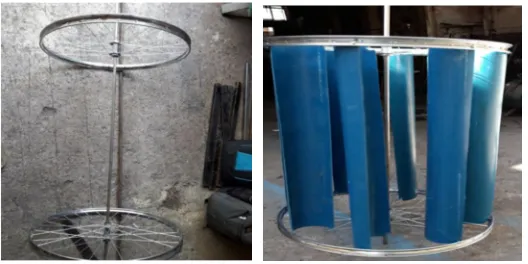
A. Mounting of Shaft & Turbine Blades
Fig 5 Mounting of shaft & Turbine blades
B. Base Assembly
Base is main supporting assembly for whole structure of vertical axis wind turbine . Material: Iron
[image:5.612.188.452.336.468.2]Dimensions: Length(0.6m) Width(0.6m) Height(0.15m)
Technology (IJRASET)
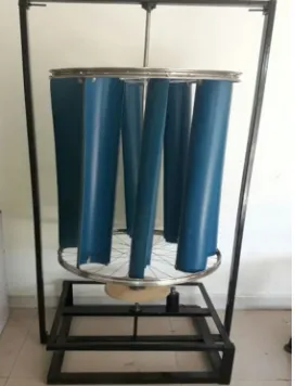
[image:6.612.239.375.91.269.2]C. Total Assembly
Fig 7 Total Assembly
VI. CALCULATION ANALYSIS
A. Calculation for Vertical Axis Wind Turbine 1) Formula:
Power P= ½*Cp*ρ*A*V3
Where , Cp= Power coefficient = 0.15 to 0.35 Velocity of air V =10-12 m/s
Air density ρ =1.12 -1.204 kg/m3
In above power formula substituting values we get,
For 60 w,
60=1/2*0.20*1.2*A*103
A=0.5 m2 Suppose r=0.26m,
A=d*h 0.5=0.52*h h=0.9615m For 100w,
100=1/2*0.20*1.2*A*103
A=0.833 m2
Suppose r=0.26m,
A=d*h 0.833=0.52*h
h=1.60256m
2) Experimental Result:
Power in watt Area in
m2
Radius in m Height in m
I. 60 w 0.500 0.26 0.9615
Technology (IJRASET)
Table- a) Dimensions of turbine height
B. Calculation for Gear Mechanism
1) Driver Gear:
a) Pitch circle diameter=250m
b) numbering of teeth=250
c) (m) Module=1m
d) Addendum=1m=1mm
e) Dedendum=1.25*m=1.25mm
f) Clearance=0.25*m=0.25*1=0.25mm
g) Working depth=2*m=2*1=2mm\
h) Whole depth=2.25*m=2.25*1=2.25mm
i) Tooth thickness=1.5708*m=1.5708*1=1.5708mm
j) Tooth space=1.5708*m=1.5708*1=1.5708mm
k) Fillet radius=0.4*m=0.4*1=0.4mm
2) Driven Gear:
a) Number of teeth=20
b) Pitch circle diameter=20m
c) Module=1m
d) Addendum=1m
e) Dedendum=1.25m
f) Clearance=0.25mm
g) Working depth=2mm
h) Whole depth=2.25mm
i) Tooth thickness=1.5708mm
j) Tooth space=1.5708mm
k) Fillet radius=0.4mm
C. Wind Power Analysis
Sr. no Wind power installed
capacity
Area Power(MW)
1 Maharashtra 456.3
2 Total in India 3595
Table- b
VII. RESULT
The project has been conducted in workshop. Analysis takes place at speed of different velocities.
A. Power Calculation
Wind speed in m/s
Voltage(V) Current :I
(mA)
Power P=VI(W)
1 2.1 120 0.252
2 2.4 143 0.343
3 2.87 157 0.450
Technology (IJRASET)
B. Advantages
This system has several advantages as follows,
1) No massive tower structure is needed
2) As the rotor blades are vertical no yaw mechanism is needed
3) A VAWT can be located nearer the ground, making it easier to maintain the moving parts
4) VAWTs do not need to turn to face the wind if the wind direction changes
VIII. CONCLUSION
This project assembly designed as simple and suitable in manner. It gives better performance in its working. We have used less costly material for its manufacturing. So, vertical wind energy based our project plant produces a clean and safely environment production of energy.
IX. ACOKNOWLEDGEMENT
It gives us an immense pleasure to present paper on the successful completion of our project. We are thankful to our guide Mr. P. D. Kumbhar for their valuable guidance. Also we express our deep sense of gratitude to Mr. S. R. Patil & Gaikwad sir. At this stage we would like to thanks to honourable Principal Mr. M. B. Joshi& Head of Dept. Mr. V. V. Jadhav for their keen interest, encourage & excellent support.
REFERENCES
[1] P.Sivachandran, P. Venktesh & N. Kamaraj, “ A Review of wind energy based decentralized power generation systems with new devlopments in India. “ [2] Wind Turbine Power Calculations,RWE npower renewables,Mechanical & Electrical Engg.Power Industry.