International Journal of Emerging Technology and Advanced Engineering
Website: www.ijetae.com (ISSN 2250-2459,ISO 9001:2008 Certified Journal, Volume 5, Issue 8, August 2015)
110
End Effector Mounted Robot Arm Kinematics for Redundant
Rigid and Flexible Links Manipulators
S. R. Chandramouli
1, G. Krishna Mohana Rao
21Dy. General Manager, ACE Designers Limited, Peenya Industrial Area, Bangalore 560058 2Professor of Mech. Engg., JNTU College of Engineering, Kukatpally, Hyderabad – 500085
Abstract—Manipulators are designed to carry out certain specific tasks. Considering end effector as a device that needs rotary orientation an attempt is made to derive robot kinematics for both rigid link manipulator arm and flexible link manipulator arm. In order to enhance the flexibility, it has been found that redundancy needs to be introduced for a rigid link robot. This increases number of joints which results in complex kinematics and complex controller design. Hence, researchers looked for alternatives and one such alternative would be flexible link continuum style manipulator arm design. Kinematics development for both flexible and rigid link (3 links) robot configurations with end effector has been derived from the first principles. Derivation compares the forward kinematics for both the architecture. It can be seen that end effector consideration makes sense from the practical application point of view. Building redundancy using flexible links helps to achieve better manoeuvrability.
Keywords—kinematics, flexible robot, continuum robot, redundant manipulator kinematics, end effector
Abbreviations—DH: Denavit & Hartenberg Zi-1 axis: axis of motion of the (i)th joint Xi axis: axis normal Zi-1 axis, pointing away Yi axis: completes right-hand co-ordinate frame
Ɵi: is the joint angle from the Xi-1 axis to the Xi axis about Zi-1 axis
di: is the distance from the origin of the (i-1)th co-ordinate frame to the intersection of Zi-1 axis with Xi axis along Zi-1 axis
ai: is the offset distance from the intersection of Zi-1 axis with Xi axis to the origin of the (i)th co-ordinate frame along Xi axis
αi: is the offset angle from the Zi-1 axis to the Zi axis about Xi-1 axis
i i
T
1represents 4x4 homogeneous transformation matrix from(i-1)th co-ordinate frame to (i)th co-ordinate frame
I. INTRODUCTION
Since decades manipulator arms are built using rigid links and find its application in various industries.
However, to increase flexibility redundancy was proposed. It can be seen considering more links such as three links manipulator provides better flexibility. It is a general practice that at the tip of the robotic arm an end effector will be attached to execute application specific tasks. However to bring increased flexibility alternative design with flexible link is proposed with end effector. Due to technological advancement in the various fields of engineering and sciences such as material science, electronics, software, computing techniques, medical surgeries helped to think of new applications for flexible link robot with end effector. These futuristic flexible robots are termed as Continuum style robots.
Kinematics design is established using Geometric and Denavit & Hartenberg approaches. The first continuum robot, OctArm, is an intrinsically actuated trunk consisting of three sections, shaped by pneumatic pressure applied to three McKibben actuators which compose each trunk section [1]. Inverse kinematics is tougher and always a challenge to robot developers. Hirose and colleagues developed kinematics in 2-D for a number of snake-like robots constructed in their lab by introducing the serpenoid curve which closely matches the shape of a snake[2]. In contrast, the modal approach followed by [3] involves linking the shape of a general mathematical curve to a high-degree-of-freedom (HDOF) robot. In this paper, an effort is made to derive forward kinematics for a three rigid link robotic arm and three section flexible link arms with end effector.
II. GEOMETRICAL REPRESENTATION OF RIGID LINK
ROBOT WITH END EFFECTOR
International Journal of Emerging Technology and Advanced Engineering
Website: www.ijetae.com (ISSN 2250-2459,ISO 9001:2008 Certified Journal, Volume 5, Issue 8, August 2015)
111
As shown in Fig.1, robot has 3 rigid links of lengths l1, l2, l3 and 3 joint rotations represented by angles Ɵ1, Ɵ2, Ɵ3 and another co-ordinate frame with end effector that can be oriented with Ɵ4 after positioning.
III. DHREPRESENTATION OF THE ROBOT
After fixing the co-ordinate frame at each joint and based on the DH rules [4], following DH parameters are computed and kept in the form of a table, Table 1.
IV. KINEMATICS OF THE RIGID LINK ROBOT
Based on the robotics transformation theory, standard form of homogeneous transformation matrix is as described below:
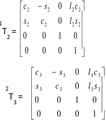
Using the DH parameters and on substitution to the above matrix, individual transformation matrix is derived.
Above matrix represents transformation from {0}th co-ordinate frame to {1}st co-co-ordinate frame. Similarly, further two transformation matrices are derived.
It is imperative that the forward kinematics of the robot can be obtained by the product of homogeneous transformation matrices.
[image:2.612.56.281.140.374.2]Z
4Fig. 1: 3 Link, 3R Robot with end effector
Ɵ
1Ɵ
2Ɵ
3X
Y
l
1l
2l
3{0}
{1}
{2}
{3}
P
(x, y)Ɵ
4Joint i
Ɵ
id
ia
iα
i1
Ɵ
10
l
10
2
Ɵ
20
l
20
3
Ɵ
30
l
30
[image:2.612.333.509.472.672.2]4
Ɵ
40
0
-90
Table 1: DH Table for Rigid link manipulator 3 Link, 3R Robot with end effector
1
0
0
0
0
1
0
0
0
0
1 1 1 1 1 1 1 1s
l
c
s
c
l
s
c
0T
1
=
1
0
0
0
0
1
0
0
0
0
2 2 2 2 2 2 2 2s
l
c
s
c
l
s
c
1T
2
=
1
0
0
0
0
1
0
0
0
0
3 3 3 3 3 3 3 3s
l
c
s
c
l
s
c
2T
3
=
1 0 0 0 0 ) , ( ) , ( ) , ( ) ,
( 1 1
International Journal of Emerging Technology and Advanced Engineering
Website: www.ijetae.com (ISSN 2250-2459,ISO 9001:2008 Certified Journal, Volume 5, Issue 8, August 2015)
112
End effector transformation matrix with reference to 3rd link tip can be defined as
Now, the final transformation is obtained by multiplication:
Thus, forward kinematics equations for the 3 link robot can be written as follows:
From the above equations, it can be inferred that the position of the end point P will not vary and can be obtained for a particular value of joint rotations. However Orientation / Rotation elements of the matrix takes care of the last end effector rotation Thus completes derivation of forward or joint space kinematics.
V. KINEMATICS OF THE CONTINUUM STYLE FLEXIBLE
LINK ROBOT
In the present case, flexible link is made up of 3 sections that constitute the robot arm. Forward kinematics for the section is derived from first principles [2]. The configuration includes end effector for which orientation is of prime importance in addition to position.
A. Continuum style flexible link robot Architecture
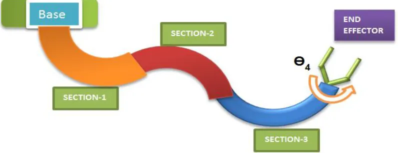
Configuration of 3 section robot & its physical structure is conceptualised & constructed from a finite number of actuated sections (3 sections) with segments, as shown in Fig. 2.
0
[T]
3=
0[T]
1x
1[T]
2x
2[T]
3
1
0
0
0
0
1
0
0
0
0
1 1 12 2 123 3 123
123
1 1 12 2 123 3 123 123
s
l
s
l
s
l
c
s
c
l
c
l
c
l
s
c
0
T
3
=
3
T
4
=
0
[T]
4=
0[T]
3x
3[T]
40
T
4
=
)
3
.(
...
0
)
2
.(
...
)
1
.(
...
1 1 12 2 123 3 24
1 1 12 2 123 3 14
Eq
p
Eq
s
l
s
l
s
l
E
p
Eq
c
l
c
l
c
l
E
p
z y x
International Journal of Emerging Technology and Advanced Engineering
Website: www.ijetae.com (ISSN 2250-2459,ISO 9001:2008 Certified Journal, Volume 5, Issue 8, August 2015)
[image:4.612.110.508.155.308.2]113
Fig. 2: Three Section flexible link robot architecture
Compared to kinematics of a conventional robot use of joint angles & link lengths does not supply enough data for describing manipulator shape. In order to arrive at the shape, above said hyper redundant robot can be constructed based on what are called SECTIONS & SEGMENTS.
Robot sections that are conceptualised are of constant curvature and are considered to have finite number of curved links [5]. Each section is constructed using multiple segments. In the present case 4 segments for each section is planned. These segments help the section to become flexible. Fig.2 shows three-section hyper redundant robot is actuated individually to bend over their length in order to obtain the required end effector position. For simplicity, single section kinematics is derived first.
[image:4.612.57.533.456.728.2]B. Geometrical Representation of Single Section
Fig.3: Single section geometry
Section curvature, fixing co-ordinate frame and arc parameters are as shown in Fig.4, where Radius of curvature = r = 1/k and Arc length = l.
C. DH Representation of 3 Section flexible link robot
Forward kinematics of a planar curve [4] with constant curvature „k‟ and arc length „l‟ can be established by 3 coupled movements (transformations). Adding additional dof for the gripper orientation similar to that of rigid link manipulator discussed in previous section would yield the following steps:
1. Rotation by an angle, Ɵ1
2. Translation by position vector X, d2 3. Rotation by an angle, Ɵ3
4. Gripper rotation/orientation, Ɵ4
Joint i
Ɵ
id
ia
iα
i1
Ɵ
10
0
-90
2
0
d
20
90
3
Ɵ
30
0
0
4
Ɵ
40
0
-90
[image:4.612.59.287.507.706.2]International Journal of Emerging Technology and Advanced Engineering
Website: www.ijetae.com (ISSN 2250-2459,ISO 9001:2008 Certified Journal, Volume 5, Issue 8, August 2015)
114
Based on the DH rules, DH table is obtained which is as shown in Table 2.
Using repetitive structure of the DH table, the transformation matrix for the forward kinematics is the product of three matrices. Hence for 3 section robot one requires 9 transformations [6].
D. Deriving 3 Section Homogeneous Transformation Matrix (without end effector)
Let us define Section parameters [7] as,
k1 and l1 are curvature & length of Section-1;
k2 and l2 are curvature & length of Section-2;
k3 and l3 are curvature & length of Section-3;
i) Section-1 Transformation Matrix:
Let Cosk1l1C1;Sink1l1S1
Substituting,
We get transformation matrix for Section-1.
Similarly transformation matrix for other two sections is obtained.
ii) Section-2 Transformation Matrix:
iii) Section-3 Transformation Matrix:
Hence, the transformation matrix from 0 to frame-9 can be computed by multiplying the matrices serially [8].
Therefore,
0
[T]
9=
0[T]
3x
3[T]
6x
6[T]
9Where,
)
(
k
1l
1k
2l
2k
3l
3Cos
=
C
123)
(
k
1l
1k
2l
2k
3l
3Sin
=
S
123and
)
(
k
1l
1k
2l
23Cos
=
C
12)
(
k
1l
1k
2l
2Sin
=S
12E. Deriving Kinematics Equations with End effector
Adding the gripper at the tip, gripper transformation matrix is:
0
T
3
=
3
T
6
=
6
T
9
=
0
T
9
=
9
T
International Journal of Emerging Technology and Advanced Engineering
Website: www.ijetae.com (ISSN 2250-2459,ISO 9001:2008 Certified Journal, Volume 5, Issue 8, August 2015)
115
Now the final transformation matrix is arrived by multiplication:
0
[T]
10=
0[T]
9x
9[T]
10Thus forward kinematics equations are arrived by comparing the final transformation with the standard form:
1
0
0
0
z z z z
y y y y
x x x x
p
a
s
n
p
a
s
n
p
a
s
n
T
Where, position of the end effector is given by
x
p
= G14....Eq(4)
y
p
=G24....Eq(5)
z
p
= 0....Eq(6)[for planar configuration] That implies,) 7 ( ... 1
1 1
2 1 12
3 12 123 14
14 Eq
k C k
C C k
C C G
F
And
) 8 ( ...
1 1
2 1 12
3 12 123 14
14 Eq
k S k
S S k
S S G
F
Thus completes the derivation of forward kinematics of a three-section planar continuum robot with end effector.
This can be extended to any number of sections [9]. We can observe in F14,G14 and F24,G24that there is no change in the magnitude of position values. However orientation or rotation matrix accommodates the end effector orientation.
VI. CONCLUSION
Forward Kinematics for both rigid link manipulator and flexible link manipulator with end effector are derived and compared. It is observed that in both the cases orientation matrix accommodates and reflects the orientation of the end effector while position co-ordinates in space are being the same. One of the applications that would elegantly describe this end effector phenomenon is GRIPPER with open/close type jaws. Robot can be positioned first, in space, and orient to suit the object that need to be grabbed.
REFERENCES
[1] M. B. Pritts and C. D. Rahn, “Design of an artificial muscle continuum robot,” in Proc. IEEE Int. Conf. Robot. Autom., New Orleans, LA, 2004, pp. 4742–4746.
[2] S. Hirose, Biologically Inspired Robots. Oxford, U.K.: Oxford Univ. Press, 1993.
[3] G. S. Chirikjian and J. W. Burdick, “A modal approach to hyper-redundant manipulator kinematics,” IEEE Trans. Robot. Autom., vol. 10, no. 3, pp. 343–354, Jun. 1994.
[4] Fu, Gonzales, Lee “Robotics, Control, Intelligence, Vision & Sensing”
[5] M.W. Hannan & I.D. Walker “Novel Kinematics for Continuum Robots”, 7th International Symposium on Advances in Robot kinematics, Slovenia, pp. 227-238, 2000
[6] SR Chandramouli, Dr. G Krishna Mohana Rao, “An Approach to Develop Hyper Redundant Robot Arm Kinematics” AIMTDR2012 4th International Conf. on Innovation for sustainable manufacturing, pp. 906-909, 2012.
[7] I. Gravagne, I.D. Walker, “Kinematic Transformations for Remotely-Actuated Planar Continuum,” IEEE Conf. on Robotics and Automation, pp. 19-26, 2000.
[8] SR Chandramouli, Dr. G Krishna Mohana Rao, “Overview of Kinematics Design of Multi Section Planar Continuum Robot”, International Journal of Engineering Research & Technology (IJERT) Vol. 2 Issue 1, January- 2013 ISSN: 2278-0181
[9] SR Chandramouli, Dr. G Krishna Mohana Rao, “Design Aspects for Developing Spatial Kinematics of a Flexible Manipulator Arm” International Conference on DESIGN, ANALYSIS, MANUFACTURING AND SIMULATION -2013, pp. 512 - 517
0