2017 2nd International Conference on Wireless Communication and Network Engineering (WCNE 2017) ISBN: 978-1-60595-531-5
Design and Implementation of Wireless Gas Meter Reading System
Based on Spread Spectrum Communication
Yu-feng WAN
1,*, Quan LIU
1and Long-han CAO
1,21
Chongqing University of Posts and Telecommunications, Chongqing, China 2
Chongqing Communication Institute, Chongqing, China
*Corresponding author
Keywords: Gas meter, Wireless meter reading system, Spread spectrum communication,
Low-power.
Abstract. Aiming at the problem that the residential residentials structure is complicated and the building density leads to the difficulty of meter reading system of wireless gas meter reading system, the reliability of ad hoc network is high and the power consumption is high. A new scheme of Wireless meter reading system used low-power MCU STM8L052 and spread spectrum communication chip SX1278 are proposed. Gas meters, repeaters and data concentrators through the spread spectrum communication transmission of data and instructions, data concentrator and gas management system through the GPRS network for real-time communication. The practical application show that the reliability of the wireless ad hoc network gas meter is high and the reliability of the network is poor.
Introduction
With the rapid development of social economy, and growing speed of urbanization, number of residential quarters increases gradually, meanwhile, the number of gas users is increasing yearly, which puts forward higher requirements for gas metering, charge and management[1]. Under steady process of science and technology, meter reading mode is changing from traditional manual operation into auto-IC card meter reading, this way could can solve the problem of reading table remotely, but users still need to pay their fee at a special place, and it cannot meet the needs of people living in a fast-paced life. Furthermore, gas companies cannot monitor the operation of the user's gas meter in real time and realize the function of time-sharing payment, which is unfavorable to gas company's gas dispatch. The installation is difficult, maintenance is also the same and costs high, it is very hard to complete large-scale applications and not suitable for current residential environment[2]. Gas meters connecting into network based on GPRS communication technology can transmit user data to the gas management system stably, but GPRS is one-way communication technology, cannot realize real-time communication function of the gas company, and high cost is unfavorable to ordinary resident user[3].Compared with GPRS, ZigBee wireless technology has advantages of lower complexity, smaller cost and less energy consumption, installation and commissioning is relatively simple, but the penetration capacity and transmission distance cannot meet the needs of current residential environment[4-5]. Spread spectrum communication is an important anti-jamming communication technology, which features in good anti-interference, multiple access communication, reliable confidentiality, resisting fading, multipath and small disturbance, and it is feasible to apply this technology to wireless gas meter reading system[6].
design show that success rate of meters reading collectively is more than 99%, and after recollecting by PAD, the rate reaches 100%, which can meet requirements of practical application.
System Architecture
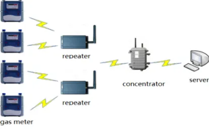
[image:2.612.198.405.183.311.2]This system is mainly composed of gas management system, data concentrators, relay stations and gas meter, shown in Figure 1. This system uses the tree network structure of depth 4. the gas management system is the root of the tree network structure; the data concentrator is its child node; the repeater is the sub node of the data concentrator; the gas meter is the terminal node.
Figure 1. System overall architecture diagram.
Data concentrator completes deployment of LoRa communication network in selected area. On the one hand, data received from concentrators is aggregated here, and will be uploaded to the server through the GPRS network, on the other hand, instructions from server are sent to relay stations through concentrators. Repeaters responsible for forwarding instructions issued by the concentrator to terminal nodes of gas meter, or forwarding data uploaded by gas nodes to a concentrator. It can also ensure a stable and reliable network when large network coverage is needed. Gas meter as terminal node take responsibility of special applications, when measurement sensor attaching on those nodes detects gas volume value and uploads it, nodes could take actions according to control instructions issued by parent node.
The System Hardware Design
Gas meter hardware includes a micro-controller, gas metering sensor module, timer, power module, valve control module, liquid crystal display and spread spectrum communication module, and an 8-bit low-power single-chip STM8L052 as control core, organizing structure of those hardware is shown in Figure 2.
[image:2.612.191.417.595.693.2]a concentrator with two parts, downlink communication module composed of SX1278 and Bluetooth communication module.
Using a tablet computer can complete the data uploading via it’s GPRS communication module, and control the receiving and sending of the spread module through Bluetooth module. While repeater is composed of micro controller, spread spectrum communication module, storage module and lithium battery, it is responsible for collecting terminal node data of gas meter.
Data Communication Protocol Design
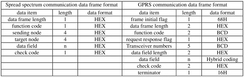
[image:3.612.95.516.304.437.2]The data transmission mode of this system is in the frame mode and the transmission sequence is binary stream. The format of communication protocol for spread Spectrum communication module is shown in table 1. The 1th byte is used to represent the length of the frame; the 2nd byte is the command code, and different command has different code; the 3rd to 6th byte is the node number that sent the command; the 7th to 10th byte indicates the destination address number to be sent, and the data field represents the parameter information to be set, such as the Terminal node table number, the step gas price, the cumulative volume, Valve status and so on; the last byte is additive and checksum.
Table 1. Data frame format.
Spread spectrum communication data frame format GPRS communication data frame format
data item length data format data item length data format
data frame length 1 HEX frame initial flag 1 68H
function code 1 HEX data frame length 2 HEX
sending node 4 HEX function code 2 BCD
target node 4 HEX request response flag 1 HEX
data field n HEX Transceiver numbers 5 BCD
check code 1 HEX data field length 2 HEX
data field n Hybrid coding
check code 2 HEX
terminator 1 16H
GPRS data transmission frame format as shown in table 1. The frame starter and Terminator are fixed to 68H and 16H respectively; the frame length is the total length including the starting character and the Terminator; the function code uses the BCD code to represent the different control instruction; the request response flag is 0 means the frame is the request frame, and the 1 means the frame is the response frame; the check code uses CRC-16 checksum.
System Software Design
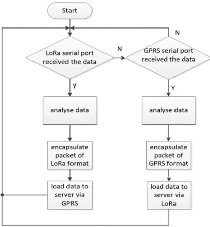
The Software Design of Data Concentrators
Figure 3. The software flow chart of concentrator.
The Software Design of the Repeater
As a bridge between the data concentrator and the terminal node of the gas meter, the repeater sends the instructions issued by the concentrator to the terminal node, and uploads the data from the terminal node to the data concentrator. Because the repeater is powered by lithium-ion batteries, it uses the same low-power design as the gas meter. When the repeater is awakened to have the data received, the data is parsed, and if the destination address of the data is the concentrator, the data is forwarded directly to the concentrator, and if the data address is a gas meter node, the wake-up instruction is sent first, and then the instruction is forwarded to the terminal node.
Gas Meter Terminal Node Software Design
According to the explosion-proof requirements, the smart gas meter can only use 4 lithium-ion batteries. In order to reduce the power consumption of the motherboard, the single chip microcomputer adopts timing wake-up mechanism. Single-chip computer set the sleep time t and detection time through the timer. every period of time t MCU awaken itself actively and detect a period of time t.
In time t, if the destination address is not detected as its own data, the node will being sleep state. if the data is detected, the node will be kept awake until the data transfer is completed, and then analyze the data, as well as complete the corresponding operation based on the requirements of the data instructions. If it is a meter-reading instruction, the table-end readings and status information are encapsulated into the spread-spectrum frame format, and sent to the repeater through the spread-spectrum module; if it is a control instruction, only the corresponding control action is completed.
System Test
the success rate of timing centralized meter reading reached 99.2%, and the success rate was 100% after point to point single read data and replacement.
Conclusion
In this paper, a wireless remote meter reading system is designed based on LoRa spread spectrum communication and GPRS technology. It changes the traditional manual and IC card reading mode, gives the best of the Lora spread spectrum modulation technology with low power consumption and transmission distance far. It also achieves the high reliability, low power consumption and real-time performance of Ad hoc. Gas company can complete the real-time monitoring of gas meter through gas management system which solves the problem of low meter-reading efficiency for gas company in essence.
Acknowledgement
This research was financially supported Chongqing IOT industrial key co-use technologies innovation subject special project (No: CSTC2015 zdcy-ztzx40007).
References
[1] Miao Yongjian. Gas enterprise demand for gas meter technology development [C]. China civil engineering society gas branch.2015 China gas operations and security conference proceedings.2015:3.
[2] Lei Y T, Li G H, Wang L Q. Design and Development of TTL-M-BUS Level Translator[C]. International Conference on Intelligent Networks & Intelligent Systems. 2012:182-184.
[3] Liu Yang, Reng Gongcang, Miao Xinqiang. The design and implementation of GPRS remote meter reading system [J]. Mechanical design and manufacturing, 2011, 49(3):248-250.
[4] Zhou Xing, Zhu Xiangdong, Yu Xiubo. The design of the ZigBee remote wireless meter reading system[J]. process automation instrumentation, 2013, 34(3):31-37.
[5] Guo dan, Li Junfang. ZigBee wireless network technology in the application of the meter reading system[J]. process automation instrumentation, 2008, 29(4):20-23.
[6] Zhao Taifei, Chen Binglun, Yuan Lu. The intelligent meter reading system based on LoRa design and implementation[J]. Computer Measurement & Control, 2016, 24(9):298-301.