http://dx.doi.org/10.4236/ica.2016.72003
How to cite this paper: Jiang, H., Lin, D., Liu, Y.C. and Song, H. (2016) Based on Adaptive Backstepping Error Control for Permanent Magnet Synchronous Motor. Intelligent Control and Automation, 7, 17-24.
http://dx.doi.org/10.4236/ica.2016.72003
Based on Adaptive Backstepping Error
Control for Permanent Magnet
Synchronous Motor
Hua Jiang, Da Lin
*, Yongchun Liu, Hong Song
School of Automatic and Electronic Information, Sichuan University of Science and Engineering, Zigong, China
Received 2 February 2016; accepted 30 April 2016; published 3 May 2016
Copyright © 2016 by authors and Scientific Research Publishing Inc.
This work is licensed under the Creative Commons Attribution International License (CC BY).
http://creativecommons.org/licenses/by/4.0/
Abstract
Permanent Magnet Synchronous Motor (PMSM) displays chaotic phenomenon when PMSM in power on or power off. At present, there are many methods to control chaos in PMSM. However, there appears oscillation in course of control chaos in PMSM, which has an effect on practical ap-plication. This paper proposes error control based on adaptive backstepping to control chaos in PMSM; an error control item is added in each step virtual control design which has control effect of unknown dynamical error on system. This scheme can eliminate oscillation in course of control chaos. Finally, the simulation results show the effectiveness of theoretical analysis.
Keywords
PMSM, Error Control, Adaptive Backstepping, Chaos Control
1. Introduction
Research on PMSM has been going on for many years due to the fact that they have many advantages over the conventional internal combustion engine vehicle, such as independence from petroleum, reliability and quiet
[1]-[3].
However there appear phenomena of chaos in PMSM when PMSM in turn on or turn off [4][5]. Chaos of PMSM is harmful. Chaos can degrade performance of PMSM, even destroy PMSM and restrict the operating range of numerous electrical and mechanical devices. The high performance of PMSM depends on the absence of chaos so it is important for PMSM to control chaos [6][7]. Due to the fact that PMSM is multivariable, non-linear and strongly coupled plant, controlling chaos of PMSM is very difficult [8].
With the development of theory of chaos, there are many methods for control and analysis chaotic system [9] [10]. For example, the OGY is a basic methodology for controlling chaos. At the same time, there are variable structure control [11], entrainment and migration control, nonlinear feedback control [12], total sliding-mode control [13] and the backstepping nonlinear control, self-constructing fuzzy neural network speed control [14], dither chaos [15], hybrid control [16] and passivity control [17].
Various ways and techniques had been successfully used to control or suppress chaos in PMSM. For example, in 2009, M. Zribi et al. proposed to control chaos in PMSM by instantaneous Lyapunov exponent control algo-rithm [18]. In 2010, D. Li et al. proposed impulsive control for PMSM [19]. In 2010, S. C. Chang proposed synchronous and control chaos in a PMSM [20]. In 2011, J. Yu et al. proposed backstepping control for the chaotic permanent magnet synchronous motor drive system [21]. In 2011, S. C. Chang et al. proposed dither signal to quenching chaos of a permanent magnet synchronous motor in electric vehicles [22]. However, these methods appear oscillation in course of control chaos in PMSM which has an effect on practical application.
In this paper, a scheme is proposed to suppress oscillation in course of control chaos in PMSM. An error con-trol item is added in the each step virtual concon-trol design which has concon-trol effect of unknown dynamical error on system. This scheme can gain more smoothly chaotic stabilization process and overcome oscillation in course of control chaos in PMSM. At the same time, all the signals in the system are bounded which based on Lyapunov function. This scheme has better transient response by simulation.
2. Problem Formulation
The dynamics PMSM, which model base on d-q axis, can be described as follows:
(
)
(
)
(
)
1
1
d d d
d d
d d
d q q d
q
q q q q q
p q p d q d q L
i
u R L i L
t i
u R i L i L
t
n i n L L i i T J
t
γ
γ
ω
ω ωψ
ω ψ βω
= − +
= − − −
= + − − −
(1)
where id, iq and ω are state variables, which denote d-axis stator current, q-axis stator current and rotor an-gular speed respectively; ud, uq and TL are d-axis external voltage, q-axis external voltage and external torque; Ld and Lq are d-axis stator inductance and q-axis stator inductance. ψγ is permanent magnet flues,
1
R is stator winding resistance, β is the viscous damping coefficient, J is rotor rotational inertia, np is the number of pole-pairs, R1, β, J, Lq, Ld, TL are all positive. Applying transformation form, x=
λ
x, and a time scaling transformation, t=τ
t, whereT
d q
i i ω
=
x ,
0 0 0 0
0 0 0 0
0 0 0 0 1
d
q
bk
k
ω
λ
λ λ
λ τ
= =
, b=Lq Ld , k=β npτψγ ,
1 q R
L L
τ = .
The system (1) can be changed into nondimensionalized form as follows:
(
)
q
d d q d
d
q q d q
q d q
L
i i i u
L
i i i u
i i i T
ω
ω γω
ω σ ω ξ
= − + +
= − − + +
= − + −
(2)
where
1 p n γ R
γ = ψ β , σ =Lqβ R J1 , 2
1 q p q q
u =n Lψγu R β, TL =L T2q L R J12 ,
2 1 d p q d
u =n Lψγu R β ,
(
)
2
q d q d p
L L L L Jn γ
ξ = β − ψ , np =1.
ω ω
= , ud =ud, uq =uq. The model can be simplified as follows:(
)
d d d d
q q d q
q L
i i i u
i i i u
i T
ω
ω γω
ω σ ω
= − + +
= − − + +
= − −
(3)
Now, for model of PMSM of smooth air-gap (3), research motor without external force which can be consi-dered PMSM no-load running and power fail interrupt, namely, ud =uq =TL =0. The system (3) can be shows as follows:
(
)
d d d
q q d
q
i i i
i i i
i ω
ω γω
ω σ ω
= − +
= − − +
= −
(4)
the parameters value of system (4), σ and
γ
, can effect on chaotic motion of PMSM greatly. Theoretically, there are many values of σ andγ
which can cause chaos occurred in system (4). For system (4),(
)
d d
d
d d d 2
q d
q d
i i
t t t
V
i i
ω
σ ω
∂ ∂
∂
∆ = + + = − +
∂ ∂ ∂ .
Due to
σ
>0, ∆ <V 0, so the system (4) is dissipative system base on dissipation theory. System (4) is chaos when γ =25 andσ
=4 base on above analysis [22]. The system (4) have three equilibrium point:(
0, 0, 0 ,)
(
γ − −1, γ − −1, γ−1)
,(
γ −1, γ −1, γ−1)
.3. Theory and Method
Set
0 0 1
0 1 0
1 0 0 A
=
,
1
2
3 y
Y y
y = ,
1
2
3 x
X x
x =
, Y =AX.
So system (4) can be change as follows:
(
)
1 2 1
2 1 2 1 3
3 1 2 3
y y y
y y y y y
y y y y
σ γ
= −
= − −
= −
(5)
To realize stability of system (4), we may add controller to the third equation of system (4), system (4) can be changed as follows:
(
)
1 2 1
2 1 2 1 3
3 1 2 3
y y y
y y y y y
y y y y u
σ γ
= −
= − −
= − +
(6)
Definite three error variables:
1 1
2 2 1
3 3 2
e y
e y
e y
α α =
= −
= −
(7)
Step 1: Base on system (7), the first derivative of e1 is
(
)
(
)
1 1 2 1 1 2 1 1 2 1
Choose the Lyapunov function candidate as:
2
1 1
1 2
V = e , (9)
then the time derivative of V1 is computed,
(
)
21 1 1 1 1 2 1 1 1 2 1 1
V =e e =e −σe +σe +σα = −σe +σe e +σαe . (10) The virtual control α1 is constructed as
1 p e1 1 p e2 2
α = − , (11)
where p1 and p2 are control parameters, 1 p1 1
σ ≤ ≤ , 0≤ p2≤1, substituting Equation (11) into Equation (10) that
(
)
(
)
(
)
2 2
1 1 1 2 1 1 1 2 2 1 1 1 1 2 1 2
V = −σe +σe e +σe p e −p e = −σ −p e +σ −p e e . (12)
Step 2: Derivative of e2, we have equation,
(
)
(
)
2 2 1 1 2 1 3 1 1 2 2 1 2 1 1 3 2 1 1 2 2
e = y −α =γy −y −y y −p e +p e =γe − e +α −e e +α −p e +p e , (13) substituting Equation. (8) into Equation (13), the Equation (13) expression is given by
(
)
(
)
(
)
(
)(
)
(
)
(
)
2
2 2 1 1 2 1 2 1 2 1 3 1 1 1 1 1
2
2 1 1 2 1 2 1 3 1 1 1 1 1 1 1 1
2 1
1 1
1
ˆ ˆ ˆ
1 1 1 1 ,
1
e p e p p p p e e e p e p e e
p
p e p p e e e p p e e p p e e
p
α σ σ σ σ γ
α σ γ γ σ γ
= − − + − + + − − + − +
−
= − − − − + − + − + − − −
−
(14)
where
σ
ˆ, γˆ are σ ,γ
estimated value,σ σ σ
= −ˆ , γ γ γ= −ˆ ,σ
and γ are parameters estimation error. Choose the Lyapunov function as follows,(
2 2)
2 1 2 2
V =V + e + +σ γ , the time derivative of V2 is given by
(
)
(
)
(
)
(
)
(
)
(
)
{
}
2 1 2 2
1 1
2 1 2 3 1 2
1 1 1 2 1 2 2 1 2 1 2
2 2 2
2
1 2 1 2
2 2 1 1
2 2
ˆ
1 ˆ
1 1 1
1 1 1
ˆ ˆ 1 1 ˆ .
1 1
V V e e
p p
e e e p
p e e e p e p e e e e
p p p
e e e e
p p p
p p
σσ γγ
σ σ σ σ
γ γ α σ γ
= + + +
−
= − − − − − + + − − −
− − −
+ − − − − + − −
− −
(15)
Choose parameters adaptive rule:
(
)
(
)
1 1
1 2 2 1 2
2
1 2 2
1
ˆ 1 ˆ
1 1
ˆ ˆ
1
p p
e e p e e m
p
e e n p
σ σ
γ γ
−
= + − −
−
= −
−
(16)
where m>0,n>0.
Construct the virtual control α2 as
(
)
2(
)
2 1 p2 p1 1 p1 ˆ p y2ˆ p e3 3
α = − + − σ+ −
, (17)
where p3∈R, p3 is a control parameter, substituting Equation (16) and Equation (17) into Equation (15), eq-uation Equntion (15) can be obtained as follows,
(
)
2 3 1(
) (
)
22 1 1 1 2 3 1 2 1 2 1 1
2 2
1
ˆ ˆ
1 1
1 1
p p
V p e e e e e e e e p e m n
p p
σ − γ γ σ σσ γγ
= − − − − + + − + − −
− −
Base on Young inequality [21], inequality (19) can be obtained as follows
(
)
(
)
2 2 2 2 1 1 ˆ 2 2 1 1 ˆ 2 2m m m m
n n n n
σσ σ σ σ σ σ
γγ γ γ γ γ γ
− ≤ − + ≤ − + − ≤ − + ≤ − + (19)
so a straightforward calculation produces the following inequality
(
)
(
)
(
)
2
2 3 1
2 1 1 1 2 3 1 2 1 2
2
2 2 2 2 2
1 2
1 1
1 1
1 1 1 1
1 .
2 2 2 2
p p
V p e e e e e e e e
p p
p e m n m n
σ γ γ
σ σ γ σ γ
− ≤ − − − − + + − − − + − − + + (20)
Step 3: Derivative of e3 results in the following differential equation,
(
) (
)
(
) (
)
(
)
3 1 2 1 3 2 2
2
1 2 1 1 3 2 1 2 1 1 1 ˆ ˆ 3 3,
e u e e e
u e e e e p p p p e
α α α
α α σ γ
= + + − + − = + + − + − − + − − +
(21)
choose p3≠1, Equation (21) can be written as follows,
(
) (
)
(
)
{
2}
3 1 2 1 1 3 2 2 1 1
3 1 ˆ ˆ 1 1 1
e u e e e e p p p
p α α σ γ
= + + − + − − + − −
−
, (22)
choose the Lyapunov function candidate as
2
3 2 3
2 1 1 2 1
V V e
p
= +
− . (23)
The time derivative of V3 is
(
)
(
) (
)
(
) (
) (
)
(
)
{
}
(
)
(
)
(
)(
)
(
)
3 2 3 3
2
2 3 1 2
1 1 1 2 3 1 2 1 2 1 2
2 2
2
3 1 2 1 3 2 2 1 1 2
2 3
1 3
2 2 3
1 1 1 2 1 2
2 3 3
1 1 1 ˆ ˆ 1 1 1 1 1 1 ˆ ˆ 1 1 1 1 1 ˆ ˆ 1 1 1 1
V V e e
p
p p
p e e e e e e e e p e m n
p p
e u e e e p p p p
P p
p p
e
p e p e m n u e e
p p e
σ γ γ σ σσ γγ
α α σ γ
σ σ σσ γγ
= + − − = − − − − + + − + − − − − + + + − + − − + − − − − − = − − − + − − + − − − +
(
) (
)
2(
)
2(
)
1 2 1 2 1 1 3 2 3 1 2 2 1 1 2
3
ˆ
ˆ ˆ
1 1 1 ,
e e e e e e p e e p p p p
e
γ γ+ α α σ γ
+ + − + − − − − + − − (24) setting
(
)
(
)
(
)
(
)
(
)
1 31 2 1 2 1 2 1 1 3 2
3 3
2 2
3 1 2 2 1 1 2
1 ˆ
ˆ ˆ
1 1 1 ,
p p
u e e e e e e e e
e e
p e e p p p p
γ γ α α
σ γ − + = − − + + + − + − − − − + − − (25)
substituting Equation (25) into Equation (24), we have the following equation.
(
)
2(
)
2 23 1 1 1 1 1 2 4 3 ˆ ˆ
V = −σ −p e − σp + e −p e −mσσ −nγγ . (26) Similar to V2,
(
)
2(
)
2 2 2 2 2 23 1 1 1 2 4 3
1 1 1 1
1 1
2 2 2 2
set
(
2 2)
2 ,
m n
β σ + γ
(
) (
)
(
)
{
1 1 4 2}
min 2 1 p , 2 p 1 , 2p 1 p , ,m n
τ = σ − σ + − ,
inequality can be obtained as follows,
2
2 2 3 2 2 2 2
3 1 2 3
3
2 1
e
V e e m n V
p
τ σ γ σ γ τ β
≤ − + + − + + + + ≤ − +
. (28)
4. Stability Analysis
Theorem 1. Consider chaotic system (6) and parameter identification (16), for bounded initial conditions, the following conclusion was established:
(1) All the signals the consistent bounded in chaos system, state error e ii
(
=1, 2, 3)
and parameter estimates error γ,σ
eventually converge to bounded sets:{
e e e1, 2, 3, ,γ σ V β τ}
Ω < .
(2) Reasonable choosing parameters m, n and p ii
(
=1, 2, 3, 4)
, state of chaotic system y1, y2 and y3 can be stability in bounded point neighborhood(
0, 0, 0 .)
Proof: Choose Laypunov function V =V3, by Equation (28) can be obtained as follows,
V≤ −τV +β . (29) Equation (29) above both sides by the same ert, inequality can be obtained as follows
eτtV≤ −τeτtV +βeτt, namely
( )
(
)
d
e e
d
t t
V t t
τ ≤β τ , (30)
integral of formulas (30) in
[ ]
0,t ,( )
( )
0 e t e t 0te da( )
0 e t(
1 e t)
( )
0V t V τ β τ τ a V τ β τ V β
τ τ
− − − −
≤ +
∫
≤ + − ≤ + . (31)For bounded initial conditions V
( )
0 , we can draw a conclusion that V t( )
is bounded base on theorem of Laypunov. We can get e1, e2, e3,σ
ˆ and γˆ consistent bounded to inequality (28). Base on virtual control(
1, 2)
j j
α = , y1, y2 and y3 are all bounded. Control input u is bounded base on Equation (25), so all the signals in chaotic system are consistent bounded.
When t→ ∞,
( )
( )
(
)
eτt 0, V t V 0 eτt β 1 eτt β
τ τ
− → ≤ − + − − < .
So state error e ii
(
=1, 2, 3)
and parameter estimation errors γ,σ
eventually converge to a bounded set{
e e e1, 2, 3, ,γ σ|V β τ}
Ω < .
From inequality (31), inequality can be obtained as follows
( )
32 T
1
1 1 1
0 e
2 2
t k
k k
e V
g
τ β
τ
− =
+ Θ Θ ≤ +
∑
, (32)where g1=g2 =1, g3= −1 p2, Θ =
[
σ γ,]
T. setting gm=max{
g g g1, 2, 3}
, base on Equation (32) inequa-lity can be obtained as follows,( )
32
1
2 0 e t
k m k
e g V τ β
τ
−
=
≤ +
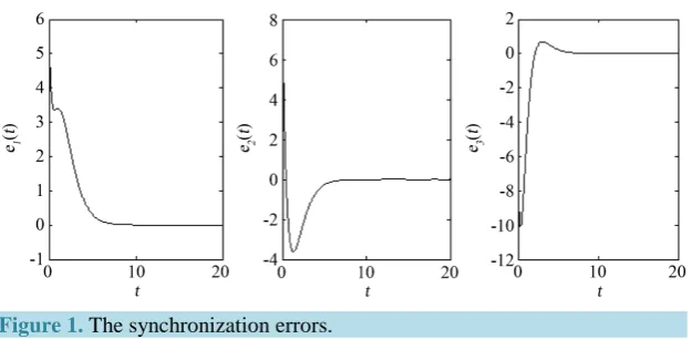
Figure 1. The synchronization errors.
Given constant µ>2gmβ τ, existing T >0, for all t≥T, error e ii
(
=1, 2, 3)
satisfy ei <µ. We reasonable choose values of m, n and p ii(
=1, 2, 3, 4)
which lead to the value ofµ
can be decreased. So,(
1, 2, 3)
i
e i= may eventually converge to a stable in bounded neighborhood
(
0,α α1, 2)
. Accordingly to Equa-tion (10) and EquaEqua-tion (17), p1, p2 and p3 are chosen smaller constant,(
α α1, 2)
can be stabled in bounded neighborhood( )
0, 0 . So system (5) can be stable in bounded neighborhood(
0, 0, 0 .)
5. Simulation Results
Choose γ =25,
σ
=4, the system (4) is chaos. Let y0 =[
8, 8,12]
T due to Y=AX , x0 =[
12, 8, 8]
T ,(
σˆ0,yˆ0) (
= 10,10)
, p1=0.5,p2=0.56,p3= −0.3,p4=1.0,(
m n,) (
= 100,100)
. Figure 1 shows the synchroni-zation errors. From Figure 1, we can see that the proposed controller and the parameters update law are effec-tive.6. Conclusion
This paper puts forward error control for permanent magnet synchronous motor with uncertain parameter based on adaptive backstepping which can effectively eliminate oscillation during the course of control chaos in PMSM. An error control item is added in the each step virtual control design which has control effect of un-known dynamical error on system. This scheme can gain more smoothly chaotic stabilization process. At the same time, all the signals in the system are bounded base on Lyapunov function. This scheme has better tran-sient response by simulation.
Acknowledgements
This research is supported by the Sichuan Province Natural Science Foundation of China (Nos. 2014GZX0008, 2016JY0179), the Innovation Group Build Plan for the Universities in Sichuan (No. 15TD0024), the High-level Innovative Talents Plan of Sichuan University of Science and Engineering (2014), the Talents Project of Si-chuan University of Science and Engineering (No. 2015RC50), the Cultivation Project of SiSi-chuan University of Science and Engineering (Nos. 2012PY18, 2012PY19, 2012PY20), and the Project of Artificial Intelligence Key Laboratory of Sichuan Province (Nos. 2011RZY05, 2014RYY05, 2015RYY01).
References
[1] Tung, P.C. and Chen, S.C. (1993) Experiment and Analytical Studies of the Sinusoidal Dither Signal in a DC Motor System. Dynamics and Control, 1, 53-69. http://dx.doi.org/10.1007/BF01968359
[2] Hoang, L.H., Slimani, K. and Viarouge, P. (1994) Analysis and Implementation of a Real-Time Predictive Current Controller for Ermanentmagnet Synchronous Servo Drives. IEEE Transactions on Industrial Electronics, 41, 110-117. http://dx.doi.org/10.1109/41.281616
[3] Chan, C.C. and Chau, K.T. (1997) An Overview of Power Electronics in Electric Vehicles. IEEE Transaction on In-dustrial Electronics, 44, 3-13. http://dx.doi.org/10.1109/41.557493
[5] Gan, J., Chan, K.T., Chan, C.C. and Jiang, J.Z. (2000) A New Surface-Inset Permanent Brushless DC Motor Drive for Electric Vehicles. IEEE Transaction on Magnetic, 36, 3810-3818. http://dx.doi.org/10.1109/20.908381
[6] Harb, A.M. (2004) Nonlinear Chaos Control in a Permanent Magnet Reluctance Machine. Chaos, Solition & Fractals, 5, 1217-1224. http://dx.doi.org/10.1016/S0960-0779(03)00311-4
[7] Zhang, B. and Mao, Z.Y. (2002) Entrainment and Migration Control of Permanent-Magnet Synchronous Motor System.
Control Theory and Application, 19, 53-56.
[8] Solsona, J. (1996) A Nonlinear Reduced Order Observer for Permanent Magnet Synchronous Motors. IEEE Transac-tions on Industrial Electronics, 43, 492-497. http://dx.doi.org/10.1109/41.510641
[9] Yahyazadeh, M., Noei, A.R. and Ghaderi, R. (2011) Synchronization of Chaotic Systems with Known and Unknown Parameters Using a Modified Active Sliding Mode Control. ISA Transactions, 50, 262-267.
http://dx.doi.org/10.1016/j.isatra.2010.10.009
[10] Wu, J., Singla, M. and Olmi, C. (2010) Digital Controller Design for Absolute Value Function Constrained Nonlinear Systems via Scalar Sign Function Approach. ISA Transactions, 49, 302-310.
http://dx.doi.org/10.1016/j.isatra.2010.03.005
[11] Xu, Z. (2007) Direct Torque and Flux Regulation of an IPM Synchronous Motor Drive Using Variable Structure Con-trol Approach. IEEE Transactions on Power Electronics, 22, 2487-2498. http://dx.doi.org/10.1109/TPEL.2007.909208 [12] Ren, H.P. and Liu, D. (2006) Nonlinear Feedback Control of Chaos in Permanent Magnet Synchronous Motor. IEEE
Transaction on Circuits and System II, 53, 45-50. http://dx.doi.org/10.1109/TCSII.2005.854592
[13] Wai, R.J. and Li, C. (2001) Total Sliding-Mode Controller for PM Synchronous Servo Motor Drive Using Recurrent Fuzzy Neural Network. IEEE Transactions on Industrial Electronics, 48, 926-944.
http://dx.doi.org/10.1109/41.954557
[14] Lin, F.J., Lin, C.H. and Shen, P.H. (2001) Self-Constructing Fuzzy Neural Network Speed Controller for Perma-nent-Magnet Synchronous Motor Drive. IEEE Transactions on Fuzzy Systems, 9, 751-759.
http://dx.doi.org/10.1109/91.963761
[15] Feeny, B.F. and Moon, F.C. (2000) Quenching Stick-Slip Chaos with Dither. Journal of Sound and Vibration, 237, 173-180. http://dx.doi.org/10.1006/jsvi.2000.3007
[16] Elmas, C. and Ustun, O. (2008) A Hybrid Controller for the Speed Control of a Permanent Magnet Synchronous Motor Drive. Control Engineering Practice, 16, 260-270. http://dx.doi.org/10.1016/j.conengprac.2007.04.016
[17] Wu, Z.Q. and Tan. F.X. (2006) Passivity Control of Permanent-Magnet Synchronous Motors Chaotic System. Pro-ceedings of the CSEE, 26, 159-163.
[18] Zribi, M., Oteafy, A. and Smaoui, N. (2009) Controlling Chaos in the Permanent Magnet Synchronous Motor. Chaos,
Solitions & Fractals, 41, 1266-1276. http://dx.doi.org/10.1016/j.chaos.2008.05.019
[19] Li, D., Wang, S.L., Zhang, X.H. and Yang, D. (2010) Impulsive Control for Permanent Magnet Synchronous Motors with Uncertainties: LMI Approach. Chinese Physics B, 19, 010506. http://dx.doi.org/10.1088/1674-1056/19/1/010506 [20] Chang, S.C. (2010) Synchronization and Controlling Chaos in a Permanent Magnet Synchronous Motor. Journal of
Vibration and Control, 16, 1881-1894.
[21] Yu, J., Chen, B., Yu, H.S. and Gao, J.W. (2011) Adaptive Fuzzy Tracking Control for the Chaotic Permanent Magnet Synchronous Motor Drive System via Backstepping. Nonlinear Analysis: Real World Applications, 12, 671-681. http://dx.doi.org/10.1016/j.nonrwa.2010.07.009
[22] Chang, S.C., Lin, B.C. and Lue, Y.F. (2010) Dither Signal Effects on Quenching Chaos of a Permanent Magnet Syn-chronous Motor in Electric Vehicles. Journal of Vibration and Control, 17, 1912-1918.