© 2018, IRJET | Impact Factor value: 6.171 | ISO 9001:2008 Certified Journal | Page 104
“A REVIEW ON I. C. ENGINE HEAD FINS DESIGN”
Mahendra Kumar Ahirwar
1,
Ravindra Mohan
2,
Gurjeet Singh31PG Research Scholar, ICOT Bhopal
2,3 Associate Professor, ICOT Bhopal
---***---
Abstract: When fuel is burned in an engine, heat is produced. Additional heat is also generated by friction between the moving parts. Only approximately 30% of the energy released is converted into useful work while remaining 70% must be removed from the engine to prevent the parts from melting. In air-cooled I.C engine, extended surfaces called fins are provided at the periphery of engine cylinder to increase heat transfer rate. That is why the analysis of fin is important to increase the heat transfer rate. The main of aim of this work is to study various researches done in past to improve heat transfer rate of cooling fins by changing cylinder fin geometry and material. The Engine cylinder is one of the major automobile components, which is subjected to high temperature variations and thermal stresses. In order to cool the cylinder, fins are provided on the surface of the cylinder to increase the rate of heat transfer. By doing thermal analysis on the engine cylinder fins, it is helpful to know the heat dissipation inside the cylinder. We know that, by increasing the surface area we can increase the heat dissipation rate, so designing such a large complex engine is very difficult. The main aim is to analyze the thermal properties by varying geometry, material and thickness of cylinder fins using CAD software.
Key words: CAD, Aluminium, Fins, Dissipation, Thermal conductivity, Transient, Fuel
I. Introduction:
We know that in case of Internal Combustion engines, combustion of air and fuel takes place inside the engine cylinder and hot gases are generated. The temperature of gases will be around 2100-2400°C. This is a very high temperature and may result into burning of oil film between the moving parts and may result it seizing or welding of same. So, this temperature must be reduced to about 150-200°C at which the engine will work most efficiently. Too much cooling is also not desirable since it reduces the thermal efficiency. So, the object of cooling system is to keep the engine running at its most efficient operating temperature. It is to be noted that the engine is quite inefficient when it is cold and hence the cooling system is designed in such a way that it prevents cooling when the engine is warming up and till it attains to maximum efficient operating temperature, then it starts cooling. To avoid overheating, and the consequent ill effects, the heat transferred to an engine component (after a certain level) must be removed as quickly as possible and be conveyed to the atmosphere. It will be proper to say the cooling system as a temperature regulation system. It should be remembered that abstraction of heat from the working medium by way of cooling the engine components is a direct thermodynamic loss.
© 2018, IRJET | Impact Factor value: 6.171 | ISO 9001:2008 Certified Journal | Page 105 Fig.1
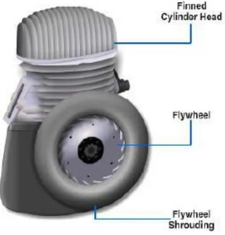
[image:2.612.206.408.82.299.2]Fins: A fin is a surface that extends from an object to increase the rate of heat transfer to or from the environment by increasing convection. The amount of conduction, convection, radiation of an object determines the amount of heat it transfers. Increasing the temperature difference between the object and the environment, increasing the convection heat transfer coefficient, or increasing the surface area of the object increases the heat transfer. Sometimes it is not economical or it is not feasible to change the first two options. Adding a fin to the object, however, increases the surface area and can sometimes be economical solution to heat transfer problems. Circumferential fins around the cylinder of a motor cycle engine and fins attached to condenser tubes of a refrigerator are a few familiar examples.
[image:2.612.196.423.414.651.2]© 2018, IRJET | Impact Factor value: 6.171 | ISO 9001:2008 Certified Journal | Page 106 Fig.3 Fuel Energy
II. LITERATURE SURVEY
G.Bahadur Vali & Krishna Veni [1] In this project they have design an assemble cylinder and cylinder head. they used two different Aluminum alloys 6061 and 7475. performed Thermal analysis on the cylinder to determine the thermal behavior for aluminum alloys for original model and also by changing the thickness of the cylinder head. They further explained that by reducing the thickness, the weight of the component reduces. By observing the thermal analysis results heat flux is more for the modified model than for original model. after comparing the result between two alloy, heat flux is more for Aluminum alloy 6061 than aluminum alloy 7475.
Abhishek Mote at el [2] they analyze of heat transfer crosswise finned surfaces using CFD software. they thought that experiment based research done by different researchers in the past is a time consuming process, hence CFD software was used to simulate the heat transfer across fins of an IC Engine and simulated results compared with experimental results.
Shubham Shrivastava & Shikar Upadhyay [3] investigate the cylinder block made in 3D software Solid works in which perpendicular fins are mounted. they modify the engine cylinder block fins, and its thickness reduced from 3 mm to 2 mm. so that weight reduced and also choose material which replace the existing materials , they analyzes Aluminium alloy 1050 for thermal analysis to evaluate the better heat transfer rate. they reduce the weight 13.2 %, of block due to modification and 2.1 % by change material without compromising with strength.
Vinay Kumar Attar & Himanshu Arora [4] They investigate Piston skirt which appear deformation at work usually causes crack on the upper end of piston head. they found that the situation becomes more serious when the stiffness of the piston is not enough and the crack appeared which may gradually extend and even cause splitting along the piston vertically. they explained the stress distribution on the piston mainly depends on the deformation of piston in order to reduce the stress concentration.
© 2018, IRJET | Impact Factor value: 6.171 | ISO 9001:2008 Certified Journal | Page 107 KM Sajesh, Neelesh Soni and Siddhartha Kosti [6] They perform CFD analysis of rectangular fins of engine. they choose two wheeler bike engine (e.g. Unicorn bike engine) and geometry is designed in Design Modeler in ANSYS 16.0.they used for is Al 6063 which was a thermal conductivity of 200 W/mK. they do modification in design of engine is made by creating holes on fin. performed transient and steady state heat transfer analysis on the engine for a period of 400 second. they study the variation of temperature on creation of various diameters like 2mm, 6mm, & 10mm holes on fin. and also perforated fin was compared with an imperforate fins to observe the differences. They observed that before a time of 400 second the transient temperature of all fins was reached to steady state temperature. and fin with a hole of 10mm diameter has decrease the minimum temperature of 1036.5 K for an imperforated fin to a temperature of 989.03K.
Mr. Manir Alam & Mrs. M. Durga Sushmitha[7] they worked on a cylinder fin body for motorcycle is modeled using modeling software CATIA. The original model is changed by geometry of the fin body and distance between the fins and thickness of the fins they used material for fin body is Cast Iron. thermal analysis is done for all the three materials Cast Iron, Copper and Aluminum alloy 6082. they observed the thermal analysis result, heat flux is more for Aluminum alloy than other two materials and also by using Aluminum alloy the body weight is less so using Aluminum alloy 6082 is better.
Swati Saini & Kagdi Dhruvin Nileshkumar [8] they performed CFD simulation for the results obtained by the experiments conducted by Thornhill et al and Yoshida et al. the heat transfer growth can be performed using the same cylinder with different fin profiles. The fin profile selected for heat transfer augmentation is developed using CAD software and simulation was carried out in similar way as performed for experimentally.
P.T. Nitnaware & Prachi S. Giri [9] They investigate the effect of fin geometries and coefficient of heat transfer coefficient and material they study for the heat loss for air cooling for an IC engine. heat transfer per unit weight of fin is larger for conical fin than the rectangular fins. that is why conical fins are preferred over rectangular cross section fins. The rate of heat transfer increases with increasing h. for small values of h the Aluminum is the better material for designing fins for air cooled engines due to less weight, high rate of heat transfer and lower cost.
H.Sumithra & B. Sandhya Rani [10] After doing the three different coupled (thermal & structural) analysis with three different materials they found that the maximum stresses for three materials. Before Modification Material Aluminum92, Aluminum96 and Aluminum Silican Nitrate the maximum temperatures are 671.45 oC, 665.74 oC and 505.73 oC. After
Modification For Material Aluminum-92, Aluminum-96 and Aluminum Silican Nitrate the maximum temperatures are 459.68
oC ,449.91 oC and 294.95 oC. Finally they concluded that the Silican Nitrate was best material among all due to factor of Safety
than other two. The Model weight is reduced after modification from 1.643kg to 1.627kg at a Density of 3000Kg/m3 .
III. PROBLEM DEFINITION
In the present paper investigation on thermal issues on automobile fins were carried out. Investigation yields the temperature behavior and heat flux of the fins due to high temperature in the combustion chamber. ANSYS work bench is utilized for analysis. The analysis is done for different models of fins that are commercially available now a days and a comparison is thus established between them. Also the material is changed so that better heat transfer rate can be obtained.
IV. CONCLUSIONS
Wide varieties of engine fins are available in the market which can be used for the Engine cylinder. Generally rectangular fins are used Engine head materials are Al alloy . If original equipment manufacturers require excellent aesthetic shape with very good heat dissipation without compromise with its associated costs then light weight material such as Al alloys can be used for engine head . But we will be used our proposed work different geometry engine head which will be analyzed in ANSYS design software.
REFERENCES
© 2018, IRJET | Impact Factor value: 6.171 | ISO 9001:2008 Certified Journal | Page 108 [2] Abhishek Mote at el "Analysis of Heat transfer through fins of an IC Engine using CFD" International Research Journal of Engineering and Technology (IRJET) e- ISSN: 2395 -0056, p-ISSN: 2395-0072 , Volume: 03 Issue: 04 | Apr-2016.
[3] Shubham Shrivastava & Shikar Upadhyay "Thermal Analysis of IC Engine Cylinder Block with Fins Perpendicular to the Axis of Piston Movement" International Journal of Mechanical and Industrial Technology ISSN 2348-7593 (Online) Vol. 3, Issue 2, pp: (139-149), Month: October 2015 - March 2016.
[4] Vinay Kumar Attar & Himanshu Arora "Transient Thermal Analysis of Internal Combustion Engine Piston in Ansys Workbench By Finite Element Method" International Journal of Engineering Sciences & Research Technology, ISSN: 2277-9655 Attar* et al., 5(6): June, 2016.
[5] Chidiebere Okeke-Richard & Sunny Sharma " Thermal Analysis and Comparison of Cylinder Blocks of 4S, SITwo Wheeler Engine Using ANSYS" International Journal of Innovative Science, Engineering & Technology, ISSN 2348 – 7968 Vol. 3 Issue 5, May 2016.
[6] KM Sajesh, Neelesh Soni and Siddhartha Kosti "Design Modification and Heat Transfer Analysis of Air Cooled Rectangular Fin Engine" International Journal of Recent Scientific Research ISSN: 0976-3031 Volume: 7(3) March -2016.
[7] Mr. Manir Alam & Mrs. M. Durga Sushmitha "Design and Analysis of Engine Cylinder Fins of Varying Geometry and Materials" International Journal of Computer Engineering In Research Trends, ISSN (O): 2349-7084 Volume 3, Issue 2, February-2016, pp. 76-80.
[8] Swati Saini & Kagdi Dhruvin Nileshkumar "Comparison of CFD Analysis of Heat Transfer Augmentation & Surface Heat Transfer Co efficient of I. C. Engine Fins at Different wind Velocities with Experimental Investigation" International Journal for Scientific Research & Development| Vol. 4, Issue 03, 2016 | ISSN (online): 2321-0613.
[9] P.T. Nitnaware & Prachi S. Giri "Design Optimization Of An Air Cooled Internal Combustion Engine Fin Using CFD" Journal of Multidisciplinary Engineering Science and Technology (JMEST) ISSN: 3159-0040 Vol. 2 Issue 11, November - 2015.
[10] H.Sumithra & B. Sandhya Rani "Design Optimization and Transient Thermal Analysis of Four Stroke Petrol Engine Cylinder Head" International Journal of Emerging Technology in Computer Science & Electronics (IJETCSE) ISSN: 0976-1353 Volume 18 Issue 2 – NOVEMBER 2015.