HARMONIC ELIMINATION IN MULTILEVEL INVERTERS
FOR SOLAR APPLICATIONS USING DUAL PHASE
ANALYSIS BASED NEURAL NETWORK
1V.J.VIJAYALAKSHMI, 2Dr.C.S.RAVICHANDRAN, 3Dr.A.AMUDHA, 4V.KARTHIKEYAN
1 Assistant Professor Department of EEE, KPR Institute of Engineering and Technology, Tamilnadu, India
2
Dean, Department of EEE, Sri Ramakrishna Engineering College, Tamilnadu, India
3
Professor, Department of EEE, Karpagam University, Tamilnadu, India
4 Assistant Professor, SVS College of Engineering, India
ABSTRACT
The objective of the proposed work is to design a multilevel inverter for solar energy applications so as to reduce the Total Harmonic Distortion (THD) and to improve the power quality. To obtain the accurate THD values inclusion of higher order harmonics is essential. A concept of Dual Phase Analysis (DPA) is introduced in this paper. DPA proposes an accurate method to determine the harmonics content in the inverters. A novel concept of application of Heuristic Optimization techniques for estimating the optimum switching angles for the voltage and harmonic control of cascaded multilevel inverters is performed. In this work, neural network based on Gradient Descent Optimization is the preferred Heuristic algorithm. The Neural Network can be trained offline and online. DPA is used in analyzing the harmonic spectrum of the multilevel inverter output. In this paper, the performance of seven level inverters for solar energy application is designed and analyzed.
Keywords:Dual Phase Analysis, Multilevel inverters, Harmonic spectrum, artificial neural Network, photovoltaic
1. INTRODUCTION:
An inverter is a power electronics device which converts Direct current into Alternating current. Harmonics are undesired oscillations in any system. The voltage and current waveforms should be sinusoidal with
constant amplitude and frequency. The
harmonics present in the system distorts the fundamental. The performance of the power electronics device depends on the harmonic content present in the system. Multilevel converters [1] emerged a solution to produce closer sinusoidal waveform. In high power converters pulse width modulation is often used to reduce selective harmonic elimination [2]. Multilevel inverters are used in low power applications [3] to reduce power quality issues. Multilevel inverters with reduced with reduced number of switches [4] are implemented to reduce the switching frequency. There are four kinds of control methods for multilevel converters. They are the selective harmonic elimination method [5], space vector control method [6], traditional Pulse Width Modulation (PWM control method and space vector PWM method. The traditional PWM, space vector
PWM and space vector modulation methods cannot completely eliminate harmonics. Another disadvantage is space vector PWM and space vector modulation methods cannot be applied to multilevel converters with unequal DC voltages. There are many optimization techniques to reduce the THD in the inverters. Genetic Algorithm [7-8] method, Artificial neural network [9], Particle swarm optimization technique [10-11] are used for finding the optimum switching angles to reduce low order harmonics. The disadvantages of the above methods are higher order harmonics are not included, so that the accurate harmonic content in the circuit cannot be determined. Inclusion of higher order harmonics is also essential to reduce the THD. Several converter topologies for PV applications can be found in the literature [12-14]. This paper proposes a converter topology suitable for PV applications with any number of levels.
2. PROBLEM FORMULATION AND
METHODOLOGY:
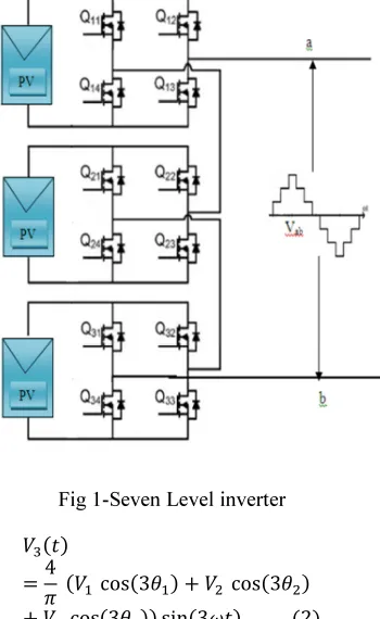
harmonics elimination technique eliminates the need for expensive low pass filters in the system. A seven level multilevel inverter is considered shown in fig (1). It has three full bridge inverter configurations with three solar panels as its input DC supply.
A. Multilevel inverter Model:
The third, fifth and the seventh harmonic of the system are given by the following set of
[image:2.595.105.280.297.582.2]equations (2-4)
Fig 1-Seven Level inverter
4 cos3 cos3
cos3 sin3 2
4 cos5 cos5
cos5 sin5 3
4 cos7 cos7
cos7 sin7 4
The fifth and seventh harmonic voltages are to be eliminated from the system. The number of harmonics that can be eliminated from the system depends on the number of levels in
the output voltage of the MLC. In an m-level converter, m–2 number of harmonics can be eliminated. Therefore, in the four-level converter in this discussion, two harmonics can be eliminated. The equations are written as follows,
4 51
V1 is the desired peak value of the fundamental
voltage.
cos5 cos5 cos5 0
(6)
cos7 cos7 cos7 0
By solving the above transcendental equations, the fifth and the seventh harmonic voltages can be eliminated from the system. The more the number of levels in the system, the more harmonics eliminated from the system.
The objective of Selective Harmonic
Elimination Pulse Width Modulation
(SHEPWM) is to eliminate the lower order
harmonics while optimizing remaining
harmonics that are removed with filter. In this paper, without loss of generality, a 7-level inverter is chosen as a case study to eliminate its low-order harmonics (fifth and seventh). A nine level inverter is also considered for evaluation purposes. Constructed fitness function and its limitations are shown in equation (7) and equation (8),
f
minθ 100 ∗"
#
$hs 501 VV
#
' 7
i = 1, 2 ….. S
Subject to
0 ( (
(8)
Where
θ1, θ2, θ3 are the switching angles
V1 is the desired fundamental harmonic,
S is the numberof switching angles, and
hs is the order of sth viable harmonicat
the output of a three-phase multilevel inverter,
e.g., h2 = 5and h3 = 7.In this switching angles
are found such that low-order harmonics (fifth
and seventh) are eliminated and the magnitudeof
the fundamental harmonic reaches to its desirable value, i.e., V1.
If the fundamental harmonic violates its set point by more than 1%, the first term of equation (7) fines it by a power of 4. Because of the use of the power of 4, corresponding penalties for any deviations under 1% get a negligible value. The second term of (7) neglects harmonics under 2% of fundamental. But, when any harmonic exceeds this limit, the objective function is subject to a penalty by power of 2. Finally, each harmonic ratio is weighted by inverse of its harmonic order, i.e., 1/hs. By this weighting method, reducing the low-order harmonics gets higher importance.
B. Dual Phase Analysis Method:
In conventional methods harmonic
spectrum are determined by FFT analysis by using the equation,
Y * Wy
where,
Yk- kth harmonic
(k=0……n-1)
W- Transform Parameter
yj- Input Sample.
The value of the FFT transform is a decaying function and therefore it tends to become zero as the number of inputs increase. The FFT for integers in increasing order yields a continuously decreasing output. When values of harmonics as high as 100 are being sought, the value of the transform is almost zero or negligible. This creates a monotonous spectrum in the magnitude of higher order harmonics with a very small decline. But the actual values of the magnitude may not be illustrated exactly by this method of evaluation. So the optimization of
harmonics may not be exact. This paper is intended to determine the higher order harmonics by dual phase analysis. It consists of two levels micro phase analysis and macro phase analysis. Micro phase analysis is the analysis of harmonic spectrum on a small scale or within a small spectrum. It is the measurement of lower order harmonics of the base frequency of analysis. In this method, the harmonics up to a predefined level are measured with respect to the base frequency. The entire magnitude spectrum is not taken into consideration. The level of harmonics is decided based on the accuracy required and the total number of stages permissible. In this
case the harmonics up to 11th order are measured
in the micro stage. The initial base frequency is 50Hz. The micro phase analysis at this frequency leads to the analysis of frequencies up to 550Hz. Since the number of harmonics considered for evolution in this method is 100, which is up to a frequency of 5000Hz, this stage is not sufficient for the complete analysis. Extending the order of harmonics will result in decrease of accuracy of the measurement.
Macro phase analysis is the large scale harmonic spectrum analysis at frequencies greater than that are possible in micro phase analysis. It is the measurement of higher order harmonics. The higher order harmonics are measured at a different scale of magnitude as compared to the base. This measurement of higher order harmonics is obtained by temporary change of base frequency. The base frequency is moved from the fundamental component to the harmonic that closely resembles the fundamental frequency. The criterion for shifting the base frequency is the next harmonic frequency that closely resembles the harmonic spectrum known
till then. Eg: If Fundamental: 100%, 1st
harmonic: 15%, 2nd harmonic: 0.3%, 3rd
harmonic: 11%, 4th harmonic: 0.23% and so on,
3rd harmonic is chosen because the ration of 0.3
(2nd harmonic) to 15 (1st harmonic) is
approximately the same as 0.23(4th harmonic) to
11(3rd harmonic). If there is absolutely no
higher order harmonics are scaled and measured in terms of lower order harmonics. Thus the analyzed higher order harmonics are at a different scale of magnitude when compared to original. Thus, we do a normalization to bring them back to the original scale. This feature normalization is carried out to remove the abnormalities in magnitude that arise out of varying magnitude scales. Now the closest resemblance to the new base frequency is selected and the next stage of micro phase analysis is carried out. This process is repeated until the maximum range of frequency chosen for analysis is reached. This process of shifting the base followed by the micro phase analysis is termed as macro phase analysis.
Now, this process is rolled back to the initial stage and the next closest resemblance is selected. The steps illustrated above are repeated again until all possible frequencies are generated. Thus all the frequencies are subject to this process at least once and have a modified value. The conflict of overlap or repetition of certain frequency values are resolved by taking maximum of the feature normalized values of all the available values and then converting it back to original scale. If a frequency has repeated analysis and more than one modified value, the value arising out of the closest harmonic base is selected as the final value. When the base is the closest, the harmonic is better identified by FFT
C. Solar cell Module:
A suitable model is derived for solar panel. The output current of the solar cell is give by the equation (9). The input parameters for designing the solar panel are directly taken from the data sheet.
IIpv –. /0 1 " 1# "
(9) Where
I- Output current
V- Output voltage Ipv –PV current
Io -Saturation current
Rs -Equivalent series resistance
Vt -Thermal voltage
Α-diode constant
Rp –Equivalent parallel resistance
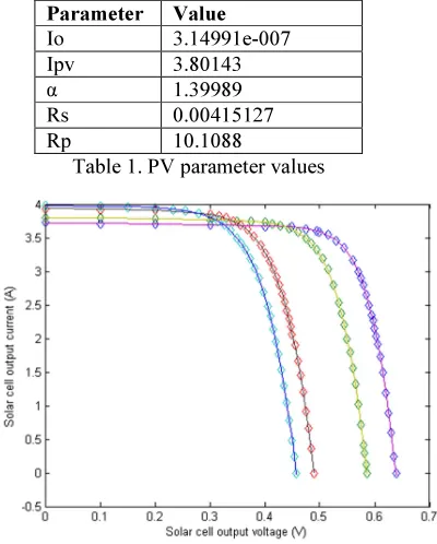
The solar panel is directly connected to the input of the H-bridge inverter. The simulated
value for solar cell is given Table (1). The V-I curves of PV module is shown in fig 2
Parameter Value
Io 3.14991e-007
Ipv 3.80143
α 1.39989
Rs 0.00415127
[image:4.595.321.521.201.450.2]Rp 10.1088
Table 1. PV parameter values
Fig 2-Solar cell V-I curves
D. Proposed Algorithm
The proposed model is shown in Fig 3. The novel technique of ANN is used in the optimization of THD by Selected Harmonic Elimination. The ANN is backed up by Gradient Descent for first order optimization and is the most effective tool for fixing the parameters of the neural network. The linear regression technique is used for filtering the huge dataset to the best group of possible switching angles that can be used to train the ANN. The training data for the network has been obtained from the
classical solutions of harmonic
Fig 3. Proposed model The algorithm is as follows.
1. Start the process.
2. Get the input from the user
(modulation index and inverter level).
3. Perform dual phase analysis for the
given level of inverter.
4. Train the linear regression based on
dual phase analysis results.
5. From the voltage profile input,
predict the switching angle range for the required modulation index.
6. Calculate error between required
and predicted output switching angles.
7. Based on the error generated, train
the artificial neural network further by back propagation algorithm.
8. Output the final switching angle to
the inverter.
9. The voltage profile from the
inverter is analyzed.
10. End the process.
3. EXPERIMENTAL RESULTS:
We consider a seven-level and a nine-level inverter for the illustration of the results, without loss of generality. The seven-level inverter consists of three H-bridge inverters constructed by IGBTs. For verifying the solutions, a 3-phase 2-kW Simulink model of 7-level inverter is built. It consists of three full-bridge inverters that are connected in a series form. Solar output voltage is give as input to the inverter. Also, the frequency of the output is assumed to be 50 Hz. The Switching angles are
obtained offline by ANN for the range of M. For
each M, we find switching angles and place it in
the pulse generator. The analysis is carried out
using the Simulink/Powergui block. The
Simulink model and the harmonic spectrum are illustrated. Low-order harmonics as well as triplen harmonics are removed.
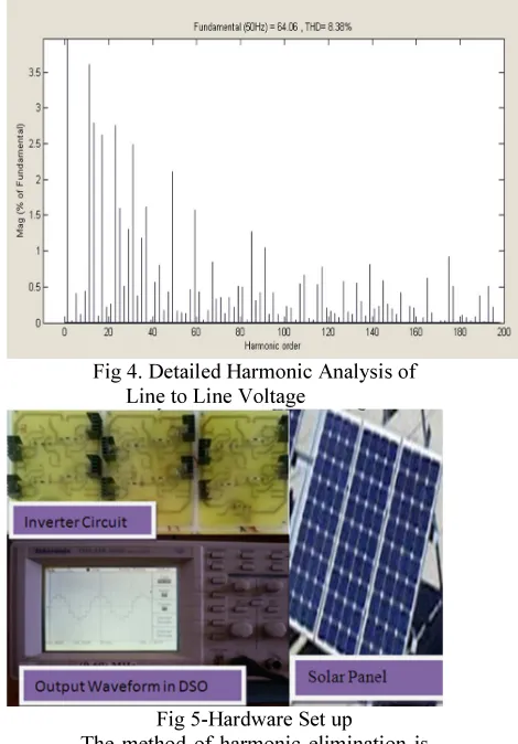
[image:5.595.314.549.251.588.2]The harmonic analysis is carried out in the Simulink/ Powergui block with a running time as 100 seconds and with 1000 cycles as FFT analysis limits. The results of the analysis are found to match closely with those found in the algorithm. Figure 4 shows the detailed harmonic spectrum of 7 level inverter. The THD value is found to be 8.38% which is lesser when compared to other methods. The hardware model is shown in fig 5.
Fig 4. Detailed Harmonic Analysis of Line to Line Voltage
Fig 5-Hardware Set up
Table 2- comparison of various methods
Method Fundamental
Voltage (V)
THD of Line Voltage
(%) Conventional
SPWM 34.73 30.63
Genetic
Algorithm 35.92 -
Bee
Algorithm 35.34 8.92
ANN 36.4 9.79
Proposed
ANN - GD 36.11 8.38
4. CONCLUSION
In this paper, the use of the DPA aided ANN is proposed to solve the selective
harmonics elimination problem in PWM
inverters. In this paper predetermination of harmonics in multilevel inverter has been carried out. The simulation result shows the accuracy of determining the harmonics. By performing the Dual Phase Analysis, the harmonics are predetermined accurately. The paper successfully demonstrates the validity of feed forward neural networks trained by back propagation for the estimation of optimum switching angles of staircase waveform generated by multilevel inverters. This technique allows successful voltage control of the fundamental as well as suppression of a selective set of harmonics.
REFERENCES:
[1] José Rodríguez, Jih-Sheng Lai and Fang
Zheng Peng, “Multilevel Inverters: A Survey of Topologies, Controls, and
Applications”, IEEE Transactions on
Industrial Electronics, vol. 49, no. 4, August 2002.
[2] Damoun Ahmadi, Ke Zou, Cong Li,Yi
Huang, and Jin Wang, “A Universal Selective Harmonic Elimination Method for High-Power Inverters”, IEEE Transactions on Power Electronics, vol. 26, no. 10, October 2011.
[3] De1.S D. Banerjee, K. Siva kumar, K.
Gopakumar, R. Ramchand, C. Patel,
“Multilevel inverters for low-power
application”, published in IET Power Electronics doi: 10.1049/iet-pel.2010.0027.
[4] Ehsan Najafi, and Abdul Halim Mohamed
Yatim, “Design and Implementation of a
New Multilevel Inverter Topology”, IEEE Transactions on Industrial Electronics, vol. 59, no. 11, November 2012
[5] M. S. A. Dahidah and V. G. Agelidis,
“Selective harmonics elimination PWM control for cascaded multilevel voltage source converters: A generalized formula,”
IEEE Trans. Power Electron., vol. 23, no. 4,
pp. 1620–1630, Jul. 2008.
[6] Amit Kumar Gupta and Ashwin M.
Khambadkone, “A Space Vector PWM Scheme for Multilevel Inverters Based on Two-Level Space Vector”, PWM IEEE Transactions on Industrial Electronics, VOL. 53, NO. 5, OCTOBER 2006.
[7] Bindu.J, Dr.S.Muralidharan,
S.Selvaperumal, M. Muhaidheen, “Genetic
Algorithm Based Selective Harmonic
Elimination in PWM AC-AC Converter”, 2011 International Conference on Recent Advancements in Electrical, Electronics and Control Engineering.
[8] Burak Ozpineci, Leon M. Tolbert and John
N. Chiasson, “Harmonic Optimization of
Multilevel Converters Using Genetic
Algorithms”, IEEE Power Electronics
Letters, vol. 3, no. 3, September 2005.
[9] Imarazene Khoukha , Chekireb Hachemi,
Berkouk El Madjid, “ANN control of Nine Level NPC Voltage Inverter Based on Selective Harmonics Elimination”
[10]Mehrdad Tarafdar Hagh, Hassan
Taghizadeh, and Kaveh Razi, “Harmonic Minimization in Multilevel Inverters Using Modified Species-Based Particle Swarm Optimization” , IEEE Transactions on Power Electronics, vol. 24, no. 10, October 2009.
[11]Ray.R.N, D. Chatterjee, S.K. Goswami,
“Harmonics elimination in a multilevel
inverter using the particle swarm
optimization technique”, published in IET
Power Electronics doi:
10.1049/iet-pel.2008.0180.
[12]Carlo Cecati, Fabrizio Ciancetta, and
Pierluigi Siano “A Multilevel Inverter for Photovoltaic Systems with Fuzzy Logic Control”, IEEE Transactions on Industrial Electronics, vol. 57, no. 12, December 2010.
[13]Engin Ozdemir, Sule Ozdemir and Leon M.
Tolbert,
“Fundamental-Frequency-Modulated Six-Level Diode-Clamped
Tansactions On Industrial Electronics, vol. 56, no. 11, November 2009.
[14]Faete Filho, Leon M. Tolbert, Yue Cao and
Burak Ozpineci, “Real-Time Selective Harmonic Minimization for Multilevel Inverters Connected to Solar Panels Using
Artificial Neural Network Angle