773
HARMONIC OPTIMIZATION IN CASCADED MULTI LEVEL
INVERTER USING FIREFLY ALGORITHM
1TAMILSELVAN R, 2 PADMATHILAGAM V
1
Asstt Prof., Department of Electrical Engineering, Annamalai University, Tamilnadu, INDIA
2
Asstt. Prof., Department of Electrical Engineering, Annamalai University, Tamilnadu, INDIA E-mail: 1
ABSTRACT
This paper presents the elimination of selected harmonics in a Cascaded Multilevel Inverter (CMLI) considering the non-equality of separate DC sources and by using Firefly Algorithm. As these equations are non-linear, asymmetric and transcendental in nature, there may exist simple, multiple or even no solution for some modulation indices │M│. Solving a non-linear transcendental equation set describing the harmonic elimination problem with non-equal DC sources using the conventional methods reaches the limitation of contemporary computer algebra software tools. The approach proposed in this paper using firefly algorithm can be applied to solve the problem in simpler manner even when the number of switching angles is increased when the determination of these angles using the conventional approach is not possible. To find feasible switching angle for all modulation Indices, to get quality output voltage by reducing the parameters like Total Harmonic Distortion (THD), Harmonic Distortion (HD), Crest Factor (CF) and Distortion Factor (DF) and to reduce the analysis time Firefly algorithm is used. The results are shown graphically for better understanding and to prove the effectiveness of the method. An eleven-level cascaded multilevel inverter is simulated in MATLAB and presented to validate the computational results.
Keywords: Cascaded Multilevel Inverter, Firefly Algorithm, Selective Harmonic Elimination (SHE).
1. INTRODUCTION
A Multi Level Inverter (MLI) is a power
electronic converter that synthesizes a nearly sinusoidal voltage waveform, from equal or unequal DC voltage inputs. The advantages of multilevel inverter over the hard switched voltage source inverter are high efficiency, low harmonic distortion low dv/dt per switching even at high voltage operation, redundancy and low electromagnetic interference [1-6]. Multilevel AC output voltage is synthesized by switching on and off the semiconductor device that desired fundamental is obtained with minimum harmonic distortion. The techniques available at fundamental frequency are space vector control and Selective Harmonic Elimination (SHE).
In SHE technique, non-linear transcendental equations characterizing harmonics are formulated. The formulated equations are solved to compute the switching angles, which produce less harmonic distortion. SHE equation are non-linear non transcendental in nature and may produce simple, multiple or even no solution for a particular modulation index. So the task is to get all possible
solution sets where they exists using reliable and less complex method. In these iterative techniques a proper initial guess and starting value of Modulation Index (MI) for which solution exists are required. Theory of resultants of polynomials has suggested in [7], [8], to solve the polynomial equations obtained from the transcendental equations. A difficulty with this approaches is that for several H-bridges connected in series, the order of polynomial become very high thereby making the computations of solutions of these polynomials very complex. Iterative techniques like Newton- Rapson method is also applied but it is not feasible, as it need a good
774 algorithm solves the transcendental equations for both equal and non-equal dc sources with negligible computational effort for all modulation indices, faster than the other methods. The application of the firefly algorithm for solving these equations is proposed in this paper. Among the three types of Multi Level Inverter (i) Diode Clamped Multi Level Inverter (DCMLI) (ii) Flying Capacitor Multi Level Inverter (FCMLI) (iii) Cascaded Multi Level Inverter (CMLI) an 11-level five H-bridges connected in series has been chosen to implement the SHE in this work. In comparison with DCMLI and FCMLI CMLI offers several advantages such as modularity, redundancy, simple for a range of modulation index. Switching angles are computed to
produce the desired fundamental voltage (V1) while
minimizing 5th
, 7th
, 11th
, 13th
, 17th
and 19th
. Third order harmonic are not consider as they are cancelled out in L-L voltages in a three phase network. The output of three single phase cascaded inverter is connected in Y / ∆ to obtain three phase configuration. The simulated results of chosen 11-level CMLI, switched by Firefly algorithm based SHE method are presented. Unequal DC voltage
input is used to feed the 11-level CMLI.
2. TOPOLOGY OF CASCADED MULTILEVEL INVERTER
The Single phase H-bridge cascaded multilevel inverter topology [Fig.1 (a)] is used to synthesize a staircase output waveform, [Fig.1 (b)] using unequal DC voltage input. As CMLI consists of separate DC sources (SDCS), the modulation control and protection requirements of each bridge are modular. The number of output voltage levels in CMLI is 2S+1, where S is the number of SDCSs. Cascaded Multilevel H-Bridge inverter has been selected for the implementation of Firefly algorithm because of its modularity, simplicity of control, requires less number of components, overall less weight and cost as compared to other type of inverters.
3. PROBLEM FORMULATION
By applying Fourier series analysis, the staircase output voltage of multilevel inverters with non-equal sources can be described as follows:
V (ωt) =4Vdc/nπ (k1 cos (nθ1) + k2 cos (nθ2) +
k3cos (nθ3) +...+ ks cos (nθs)) sin (nωt) (1)
Where ki*Vdc is the magnitude of i th
DC voltage,
Vdc is the nominal DC voltage, and the switching
angles θ1–θs must satisfy the following condition
0 ≤ θ1 ≤ θ2 ≤ … ≤ θs ≤ π/2 (2)
Among ‘s’ number of switching angles, generally one switching angle is used for fundamental voltage selection and the remaining (s-1) switching angles are used to eliminate certain predominating lower order harmonics. For 5 H-bridge connected in series, 4 predominantly lower order harmonics can be eliminated while producing the desired
fundamental voltage (v1). To eliminate 5
th
, 7th
, 11th
, 13th
order harmonic while general v1, the equation
set (3) must be satisfied.
k1 cos(θ1) + k2 cos(θ2) +…..+k7cos(θ7)=7M
k1 cos(5θ1) + k2 cos(5θ2) +…..+k7cos(5θ7)=0=V5
k1 cos(7θ1) + k2 cos(7θ2) +…..+k7cos(7θ7)=0=V7
k1cos (11θ1)+ k2 cos(11θ2)+…..+k7cos(11θ7)=0=V11
k1 cos(13θ1) +k2cos(13θ2)+…..+k7cos(13θ7)=0=V13
(3) Where modulation index M is defined as M = V1/sVdc and V1 is the fundamental of the
required voltage.
The equation (3) is a system of 5 transcendental equations known as Selective Harmonic Elimination (SHE) equations, in terms of five unknown’s θ1, θ2, θ3, θ4 and θ5. For the given value
of ‘M’ (from 0 to1), it is required to get complete and all possible solutions of (3) when they exist with minimum computational burden and complexity.
Iterative technique can be used to solve this set of non-linear transcendental equations (5), Fire Fly Algorithm (FFA) is used in this work. The objective function which has to be minimized using FFA is given as,
775 A key issue in designing an effective multi level inverter is to ensure that the total harmonic distortion (THD) in the voltage output waveform is small enough. To do so requires a fast computing algorithm to determine when the switching should be done so as to not produce harmonics. Therefore to do so Firefly optimization algorithm has been proposed in this work. The FFA is inspired by the flashing behavior of fireflies. Implementation of FFA based harmonic optimized switching angle calculation for an eleven level CMLI is presented in the flowchart below.
5. COMPUTATIONAL RESULT
The calculation of switching angles by the proposed Firefly algorithm for an eleven level CMLI is accomplished in the MATLAB programming environment. All solution sets were computed by incrementing M in the steps of 0.001 from 0 to 1. The number of generation that evolves depends on whether an acceptable solution is reached or a set number of iteration is exceeded. In this paper, the maximum-number-of iteration criterion is used to stop algorithm. Moreover, the threshold of the cost to accept a solution is chosen to be 10-4
. However, most of time, the resulted cost
value reached by the algorithm is below 2×10⁻⁵
. The summary of the results obtained are shown (only in the range of M where solution occur)
[image:3.595.316.493.126.256.2]below for the values of Ki given in table I.
Table I. VALUES OF Ki USED
K1 K2 K3 K4 K5
1.2 0.94 0.85 0.82 0.76
[image:3.595.314.502.302.442.2]Fig.2 Switching Angles Versus M For An Eleven Level Cascaded Inverter
Fig.3 Objective Function Value Versus M For An Eleven Level Inverter
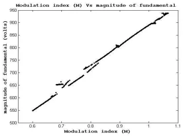
Fig.4 Fundamental Components Versus M For An Eleven Level Cascaded Inverter
Fig 2-4 depicts the switching angles, objective function and fundamental component for various modulation indexes.
[image:3.595.93.287.516.693.2]For each of the solution sets as computed above, Total harmonic distortion (THD), distortion factor compute and displayed for MI 0.6 to 1.1 in Fig. 5 and 6.
[image:3.595.317.504.574.692.2]776 Fig.6 DF Versus M For A Eleven Level Cascaded
Inverter 6. SIMULATION RESULTS
In order to validate the computational results, switching angle a simulation is carried out in MATLAB/SIMULINK software for an 11-level CMLI un-equal dc sources. The results are presented for an 11-level cascaded H-Bridge inverter. The magnitudes of the dc voltage levels in the simulation are considered as follows, which
correspond to the ki (k1-k5) values has been
assumed depending upon the magnitude of available voltage sources. Considering the voltage balancing problem the variation of magnitude of voltage is restricted in a bandwidth. So the voltage magnitude of dc sources are assumed as
Vdc1 = 120v, Vdc2 = 94v, Vdc3 = 85v, Vdc4 = 82v
Vdc5 = 76v and nominal Vdc=100v
The output phase and line voltages and the corresponding fast Fourier transform (FFT) analysis are shown in Fig.7 for modulation index M=0.6. The output phase and line voltage and also the corresponding FFT analysis for M=1 is shown in Fig.8. The output phase and line voltage and also the corresponding FFT analysis for M = 1.062 case are shown in Fig.9. From the FFT analyses for all cases, the 5th
, 7th
, 11th
and 13th
order harmonics are completely eliminated from the output voltages of the CMLI.
7(A) Output Voltage
7(B) FFT Analysis For Phase Voltage
7(C) Output Line Voltage
7(d) FFT analysis for line voltage
Fig.7 Simulation Results Of A 11-Level Inverter For M = 0.6
777
8(B) FFT Analysis For Phase Voltage
8(C) Output Line Voltage
8(D) FFT Analysis For Line Voltage
Fig.8 Simulation Results Of A 11-Level Multilevel Inverter For M = 1
9(A) Output Phase Voltage
9(B) FFT Analysis For Phase Voltage
9(C) Output Line Voltage
9(D) FFT Analysis For Line Voltage
Fig.9 Simulation Results Of A 11-Level Multilevel Inverter For M = 1.062
7. CONCLUSION
778 REFRENCES:
[1] Fang Zheng Peng and Jih-Sheng Lai, “A Multilevel Voltage-Source Inverter with Separate DC Sources for Static Var
Generation”, IEEE Transaction on Industry
Applications, vol. 32, no. 5,
September/October 1996, pp. 1130-1138. [2] Jose Rodriguez, J S Lai, and F. Z. Peng,
“Multilevel Inverters: A Survey of Topologies,
Controls, and Applications”, IEEE
Transaction on Industrial Electronics, vol. 49,
no. 4, August 2002, pp. 724-738.
[3] F. Z. Peng, J. W. McKeever, and D. J. Adams, “Cascade Multilevel Inverters for Utility
Applications”, IECON Proceedings of
Industrial Electronics Conference, vol. 2,
1997, pp. 437-442.
[4] L.M. Tolbert, F.Z. Peng, and T.G. Habetler, “Multilevel converters for large electric
drives”, IEEE Transactions on Industry
Applications, vol. 35, no. 1, Jan. /Feb. 1999,
pp. 36-44.
[5] R. Lund, M.D. Manjrekar, P. Steimer, and T.A. Lipo, “Control strategies for a hybrid
seven-level inverter”, Proceedings of the
European Power Electronic Conference ,
Lausanne, Switzerland, September 1990. [6] John N. Chiasson, Leon M. Tolbert, Keith J.
McKenzie, Zhong Du, “A new approach to solving the harmonic elimination equations for
a multilevel converter”, IEEE Proceedings on
Industry Applications , Salt Lake City, UT,
Oct.12-16, 2003, pp. 640-645.
[7] Burak Ozpineci, Leon M. Tolbert, John N.
Chiasson, “Harmonic Optimization of
Multilevel Converters Using Genetic
Algorithms”, IEEE Power Electronics, vol. 3,
no. 3, September 2005, pp.92-95.
[8] X.-S. Yang, “Firefly algorithms for
multimodal optimization”, in: Stochastic
Algorithms: Foundations and Applications,
SAGA 2009, Lecture Notes in Computer Sciences, Vol.5792, pp. 169-178.
[9] John N. Chiasson, Leon M. Tolbert, Keith J. McKenzie, Zhong Du, “Control of a
Multilevel Converter Using Resultant
Theory”, IEEE Transaction on Control
Systems Technology, vol. 11, no. 3, May 2003,
pp. 345-353.
779
780
Flowchart For Proposed Fire-Fly Algorithm
YES START
Read inverter data (Vdc, m, ns) & FFA
data (nf,alpha, beta0,delta,itermax)
For all fireflies initialize ‘Ө’ randomly
Өij = rand (0 to π/2)
For all i=1 to nf j=1 to ns
Iter = 1
Evaluate objective function for all fireflies Fi = f(Өi1, Өi2, … Өins) using eqn(3)
For all i=1 to nf
Rank the fireflies based on their objective function such that the firefly with minimum value of objective function is ranked #1
nӨij = Өij
A i = 1
B
YES NO
NO
is Iter > itermax Iter=Iter+1
B
Print the first firefly as the best solution.
STOP
beta = beta0 * exp( - gamma * r2 )
For all j=1 to ns Өij = [Өij×(1-beta)]+[nӨkj×beta]+[alpha×(rand -0.5)]
is k > i k=k+1
i=i+1
A
k = 1
Find distance between fireflies ‘i’ and ‘k’ r =