ii
INTRUDER LOCALIZATION WIRELESS SENSOR NETWORK RADAR DESIGN WITH VIRTUAL REFERENCE TAGS
HADI ABDULLAH
A thesis submitted in
fulfillment of the requirement for the award of the Degree of Master of Electrical engineering
Faculty of Electrical and Electronic Engineering Universiti Tun Hussein Onn Malaysia
vi
ABSTRACT
vii
TABLE OF CONTENTS
DECLARATION iii
DEDICATION iv
ACKNOWLEDGEMENT v
ABSTRACT vi
TABLE OF CONTENTS vii
LIST OF TABLES x
LIST OF FIGURES xi
LIST OF SYMBOLS AND ABBREVIATIONS xvii
LIST OF APPENDICES xx
LIST OF PUBLICATIONS xxi
CHAPTER 1 INTRODUCTION 1
1.1 Overview 1
1.2 Problem statement 4
1.3 Objectives of the Study 6
1.4 Scope of the study 6
1.5 Aim of the study 7
1.6 Significance of the Study 7
1.7 Novelty 8
1.8 Project Schedule 8
viii
CHAPTER 2 LITERATURE REVIEW 10
2.1 RADAR 11
2.1.1 Monostatic radar 11
2.1.2 Bistatic radar 12
2.1.3 Multistatic radar 13
2.2 Ultra Wide Band (UWB) 14
2.2.1 Advantages of using UWB technologies 16
2.3 Wireless Sensor Network (WSN) 17
2.3.1 Network characteristics 17
2.3.2 Wireless sensor network applications 18 2.3.3 Wireless sensor network design objectives 21 2.4 Localization system in wireless sensor networks 22
2.5 Range estimation 22
2.5.1 Received Signal Strength Indicator (RSSI) 23 2.5.2 Time/Difference of Arrival (ToA/TDoA) 24
2.5.3 Angle of Arrival (AoA) 26
2.5.4 Range estimation method selection 27
2.6 Position computation 27
2.6.1 Trilateration and multilateration 28
2.6.2 Triangulation 30
2.6.3 Probabilistic approaches 30
2.6.4 Bounding box 32
2.6.5 Comparison of position computation methods 33
2.7 Localization algorithms 34
2.7.1 Ad Hoc Positioning System (APS) 35 2.7.2 Recursive Position Estimation (RPE) 36
2.7.3 Directed 37
2.7.4 Localization Mobile Beacon (LMB) 38 2.7.5 Global Positioning System (GPS) 39 2.7.6 Cricket Localization System (CLS) 40 2.7.7 Localization Algorithm summary and
comments 41
2.8 Virtual Reference tags (VRTs) 42
ix
2.10 Comparative designs 43
CHAPTER 3 METHODOLOGY 66
3.1 System overview 66
3.2 Radar sensor network design 67
3.3 Received Signal strength calculation 68
3.4 Virtual Reference tags design 69
3.4.1 VRTs as clutter removal 72
3.5 System design for automobiles 76
3.5.1 Assistance of WSN to vehicle driver 79
CHAPTER 4 RESULTS AND ANALYSIS 82
4.1 Introduction 82
4.2 Intruder detection for single point 82 4.3 Target localization and path detection 84 4.3.1 WSN radar with 29, 41, 55 and 89 VRTs 87 4.3.2 WSN radar with 131, 209, 305 and 811 VRTs 92
4.3.3 WSN radar with 1721 VRTs 96
4.3.4 Presence of object in surveillance area 98
4.4 Driver alerting method 100
4.5 Findings and summary 101
CHAPTER 5 CONCLUSION AND FUTURE WORK 106
5.1 Summary of research 106
5.2 Contribution 107
5.3 Conclusion 107
5.4 Future work 108
REFERENCES 109
APPENDIX 114
A Gantt Chart 114
B Calculated path VRT 29, 55 and 89 115 C Calculated path VRT 209, 305 and 811 125
D Calculated path VRT 1721 130
x
LIST OF TABLES
1.1 Comparison existing methods used for distance/angle
estimation 3
2.1 A comparison of PSD of commonly used broadcast
systems (Ghavami et al., 2004) 15
2.2 A comparison between position computational
methods (Boukerche, 2009) 34
2.3 A comparison between position computational
methods (Boukerche, 2009) 41
2.4 The basis sequence set (Ergut et al., 2008) 48
2.5 Design parameters 52
2.6 Comparative methods summary 64
3.2 Surveillance range of WSN in vehicle 79
4.1 System parameters 85
4.2 Number of VRTs with their surveillance regions. 87
4.3 Actual and calculated object locations 99
4.4 Calculated error mean using specific number of VRTs in surveillance area of 80X80 meters 102 4.5 Comparison of presented WSN design with existing
xi
LIST OF FIGURES
2.1 Simple block diagram of a monostatic radar
system by Merrill l. Skolnik 12
2.2 Bistatic radar geometry by Nicholas J. Willis 13 2.3 Multistatic radar with three transmitters and
one receiver (Amanipour &Olfat, 2011) 14 2.4 Low-energy density and high-energy density
systems (Ghavami et al., 2004) 16
2.5 WSN in surveillance area for enemy target
localization (Stojmenovic, 2005) 19
2.6 WSNs application as disaster monitoring
system (Stojmenovic, 2005) 20
2.7 Decreasing signal transmitted by a transmitting node. The signal is send with specific signal
strength which decreases as the square of distance. In real world different other factors also contribute in decreasing signal strength (Boukerche, 2009) 23 2.8 Distance calculating methods: (a) ToA, one signal
is transmitted by transmitting and received by receiving node and the difference of time is used to calculate the distance between them. (b) TDoA, two signals are transmitted and their difference of time in arrival is used to calculate distance between
two nodes (Boukerche, 2009) 26
2.9 AoA calculation nodes in the network
(Niculescu &Nath, 2003) 27
xii 2.11 Theoretical model of multilateration
(Boukerche, 2009) 29
2.12 (a) Unknown node location computation by reference nodes using angle of arrival information. (b) Unknown node self position computation using information of angle of
arrival from reference nodes 30
2.13 Probabilistic approach: (a) probability of location of unknown node with one reference node. (b) Probability of location of unknown node using two reference nodes reduces to two possible locations. (c) Probability of unknown node location using three reference nodes having highest probability at a single point (Sichitiu &Ramadurai, 2004; Boukerche, 2009) 31 2.14 Bounding box method using three reference
nodes. The intersection of three bounding
boxes gives a new box region which is shown as shaded region in this figure. Centre of shaded bounding box gives location of unknown node
(Sastry, 2001) 32
2.15 Localization Algorithm geometric sketch using DV-Hop(Niculescu &Nath, 2001) 35 2.16 RPE localization algorithm phases. (a) Unknown
nodes choose their nearest reference nodes. (b) The unknown nodes estimate their distance from reference nodes. (c) Once distance is known one of position estimation method is used to location unknown node. (d) after localization this newly discovered node acts as reference node to locate other unknown nodes (Boukerche, 2009) 36 2.17 (a) DPE with origin and coordinates
xiii two reference nodes and recursion direction to estimate correct position of unknown node in calculated pair (de Oliveira et al., 2005) 37 2.18 Localization of unknown node using position
information of beacon or reference node
(Sangho et al., 2009) 38
2.19 Possible trajectories of mobile reference node in surveillance area. (a) Straight line trajectory. (b) Less linear trajectory. (c) Spiral
trajectory (Sangho et al., 2009) 39
2.20 Satellites orbiting around the Earth
(El-Rabbany, 2002) 39
2.21 Localization in GPS using ToA of signal as range estimation and trilateration as position
estimation (El-Rabbany, 2002) 40
2.22 (a) Correct alignment of a Cricket ultrasonic transmitter. (b) Evaluating boundary performance. (Nissanka B. Priyantha, 2000) 41 2.23 Anti intruder scenario (Enrico Paolini, 2008) 44 2.24 Equi position point pairs in bistatic
radar: (a) Equi-ToA positions (ellipse). (b) Equi power positions (cassini oval)
(Enrico Paolini, 2008) 44
2.25 Minimum ellipse and maximum Cassini oval. The area inside the maximum Cassini oval is where the target can be detected. The gray area is a blind zone where targets cannot be
detected (Enrico Paolini, 2008) 45
2.26 Configuration of radar sensor nodes
(Enrico Paolini, 2008) 46
xiv 2.28 Effects of external objects on the multipath
profile of UWB signals. a) Multipath profile when there is not any object in the medium, b) Multipath profile is modified due to reflecting signals coming from the external object
(Ergut et al., 2008) 48
2.29 Zigbee module and antenna (ChulYoung et al., 2010) 49 2.30 Radar design block diagram (ChulYoung et al., 2010) 50 2.31 Experimental conditions (ChulYoung et al., 2010) 50 2.32 localization of unknown node (Wu et al., 2011) 51 2.33 Presented grid model of WSN design (Wu et al., 2011) 52 2.34 Number of beacon nodes verses localization error
(Wu et al., 2011) 52
2.35 Tag based LANDMARC systems (Ni et al., 2011) 53 2.36 Reference tags scenario (Ni et al., 2011) 54 2.37 Hybrid RFID and WSN design (Ni et al., 2011) 55 2.38 Arrangement of VRTs, real reference tags and RFID reader in surveillance area (Junhuai et al., 2011) 56 2.39 WSN placement in surveillance area
(Junhuai et al., 2011) 56
2.40 Placement of virtual reference tag in surveillance
area (Ng et al., 2011) 57
2.41 Layout of the positioning environment
(Ng et al., 2011) 58
2.42 Communication between nodes
(Ahmadi et al., 2012) 58
2.43 Sensor position calculation (Ahmadi et al., 2012) 59 2.44 Sensor7 determines that Anchor2 is its
parent-anchor (Safa &Yassine, 2012) 60 2.45 Illustration of how the base station uses
xv 2.46 Illustration of the network structure and
the angle estimation. The anchor node is equipped with two antenna elements spaced
by a distance d (Weile et al., 2013) 62
2.47 Illustration of the improved angle estimation using AODs between the multiple parallel arrays and the receiving sensor
(Weile et al., 2013) 63
3.1 Radar design over view 67
3.2 Equi power positions 68
3.3 Geometrical overview of VRTs mapping over
surveillance area 71
3.4 Suveillance area regions of VRT 72
3.5 Geometric representation of clutter
effect in radar systems 73
3.6 Objects in the surveillance area mapped with VRTs 74 3.7 (a) Flow chart of RSSI position estimation
system. (b)Flow chart of presented WSN designed with VRTs to assist in target localization and clutter removal of object other than target
compared with actual. 75
3.8 State diagram of the proposed WSN algorithm for intruder localization and path detection. 76
3.9 WSN sensor nodes location on vehicle 77
3.10 RSSI range estimation method in WSN
(M. Ghavami, 2004) 77
3.11 Surveillance area levels and ranges of three receivers placed in front and two sides of
vehicles (rectangle) 78
3.12 Mercedes-Benz GLK-CLASS
(Mercedes-Benz, 2013) 79
3.13 Flow chart of proposed WSN design in vehicles 80
3.14 Three surveillance levels of receiver1 81
xvi 4.2 Division of surveillance area of 10X10 meters
into VRT regions 83
4.3 Target localization (a) For target located at (8,7).
(b) For target located at (2,3) 84
4.4 WSN radar simulation setup 85
4.5 Actual path of target in surveillance area 86
4.7 Actual and calculated path using 41 VRTs 88
4.6 Actual and calculated path using 29 VRTs 88
4.9 Actual and calculated path using 89 VRTs 89
4.8 Actual and calculated path using 55 VRTs 89
4.10 Error in localization vs. time for 29 VRTs 90 4.11 Error in localization vs. time for 41 VRTs 90 4.12 Error in localization vs. time for 55 VRTs 91 4.13 Error in localization vs. time for 89 VRTs 91 4.14 Actual and calculated path using 131 VRTs 92 4.15 Actual and calculated path using 305 VRTs 93 4.16 Actual and calculated path using 209 VRTs 93 4.17 Error in localization vs. time for 131 VRTs 94 4.18 Actual and calculated path using 811 VRTs 94 4.19 Error in localization vs. time for 209 VRTs 95 4.20 Error in localization vs. time for 305 VRTs 95 4.21 Error in localization vs. time for 811 VRTs 96 4.22 Actual and calculated path using 1721 VRTs 97 4.23 Error in localization vs. time for 1721 VRTs 98 4.24 Introduction of object other than target in
surveillance area 99
4.25 Actual and calculated path with presence of object in surveillance area
100 4.26 Steering wheel driver alert design which provides
xvii
LIST OF SYMBOLS AND ABBREVIATIONS
P - Power transmitted in watts (W). B - Bandwidth of the signal in hertz (Hz).
r
P
- Received signal strengtht
P
- Transmitted signal strengthr
G
- Receiver antenna gaint
G
- Transmitter antenna gain
- Wavelength of transmitted signald
- Distance between nodesL
- System loss2 t
h
- Height of transmitter antenna2 r
h
- Height of receiver antenna1
t
- Time of departure of signalLOS UWB r
P - Line of sight received signal strength in UWB
et t
UWB r
Parg - Target reflected received signal strength in UWB
2
t
- Time of arrival of signalr
xviii
d
- Distance between transmitting and receiving nodes
s
- Slower propagation speed signal (ultrasound signal)y
x, - Coordinates of unknown node
3 3 2 2 1 1 , , , , y x y x y x
- Locations of the reference nodes
3 2 1,d ,d
d - Distance of unknown node from reference nodes
t
S - Total surveillance area
r
S - Surveillance region of each VRT
n iVRTs
1- Total number of VRTs used
L
f
- Lower frequency
- The minimum delay between direct and reflected signalc
- Speed of lightAoA - Angle of Arrival
APS - Ad Hoc Positioning System
BB - Bounding box
CLS - Cricket Localization System
DA - Design Accuracy
DPE - Directed Position Estimation GPS - Global Positioning System
ID - Indoor
LMB - Localization Mobile Beacon
ML - Multilateration
OD - Outdoor
P - Probabilistic
xix
RE - Range estimation
RN - Reference Nodes
RT - Reference Tags
RRT - Real reference tags
RSSI - Received Signal Strength Indicator RPE - Recursive Position Estimation RFID - Radio Frequency Identification
SA - Surveillance area
TL - Trilateration
TA - Triangulation
TDoA - Time Difference of Arrival ToA - Time of Arrival
xx
LIST OF APPENDICES
APPENDIX TITLE PAGE
A
Table A.1: Gantt chart of the research 114
B
Table B.1: Actual Path of target 115
Table B.2: Calculated path of target using 29, 55 and
89 VRTs. 120
C
Table C.1: Calculated path of target using 209, 305 and
811 VRTs 125
D
Table D.1: Actual and Calculated path of target using
1721 VRTs 130
E
Table E.1: Measurement of radar cross section of
different shapes 136
Figure E.1: Radar cross section comparison of
xxi
LIST OF PUBLICATIONS
Journals:
(i) Hadi Abdullah, Ijaz Khan, Mohd Shamian Bin Zainal (2013), “Improved UWB wireless sensor network algorithm for human intruder localization.” Research Journal of Applied Sciences, Engineering and Technology. © Maxwell Scientific Organization.
(ii) Hadi Abdullah, Ijaz Khan, Mohd Shamian Bin Zainal (2012) “Ultra Wide Band localization and tracking hybrid technique using VRTs.” International Journal of Integrated Engineering, UTHM, Vol. 4 No. 3 (2012).
(iii) Hadi Abdullah, Ijaz Khan, Mohd Shamian Bin Zainal (2013) “Low cost Ultra Wide Band hybrid radar design using virtual reference tags as road safety feature in vehicles”, Journal of Information and Communication Technologies, Vol. 3, No. 4, April (2013).
(iv) Hadi Abdullah, Ijaz Khan, Mohd Shamian Bin Zainal (2013) “Clutter removal technique using virtual reference tags for intruder localization in ultra wide band radar network.”, International Journal of Engineering and Applied Sciences, EAAS, Vol 3, No. 3, (2013).
xxii
(vi) Ijaz Khan, Hadi abdullah, Mohd Shamian Bin Zainal (2013) “Efficient eyes and mouth detection algorithm using combination of Viola Jones and skin color pixel detection.” International Journal of Engineering and Applied Sciences, EAAS, Vol 3, No. 3, (2013).
xxiii
Proceedings:
(i) Hadi Abdullah, Ijaz Khan, Mohd Shamian Bin Zainal “Proposed Wireless Sensor Network in vehicles for road surveillance”, IEEE conference on system, process and control (ICSPC 2013), 13-15 December 2013, Kuala Lumpur, Malaysia.
(ii) Hadi Abdullah, Ijaz Khan, Mohd Shamian Bin Zainal “Improved range estimation method in WSN for human intruder localization” 10th IEEE colloquium on signal processing and its applications (CSPA 2014), 7-9 March 2014, Kuala Lumpur, Malaysia.
(iii) Hadi Abdullah, Ijaz Khan, Mohd Shamian Bin Zainal “Wireless sensor network algorithm for localization based on ToA and RSSI” Malaysian Technical Universities Conference on Engineering & Technology (MUCET 2013), 2-4 December 2013, Kuantan, Malaysia.
(iv) Hadi Abdullah, Ijaz Khan, Mohd Shamian Bin Zainal “Improved Received Signal Strength Indicator localization algorithm with Virtual Reference Tags”, Prosiding Seminar Kebangsaan Aplikasi Sains dan Matematik 2013 (SKASM2013) Batu Pahat, Johor, 29 – 30 October 2013.
(v) Ijaz Khan, Hadi Abdullah, Mohd Shamian Bin Zainal “Vision based composite approach for lethargy detection” 10th IEEE colloquium on signal processing and its applications (CSPA 2014), 7-9 March 2014, Kuala Lumpur, Malaysia.
xxiv
1CHAPTER 1
INTRODUCTION
1.1 Overview
2 tanks etc. Smaller and high speed targets are able to be detected using more advance hardware and algorithmic techniques (Farina, 1987).
Ultra Wide band (UWB) have evolved in wireless communication systems due to its vast applications while co-existing with other licensed and unlicensed narrow band systems. To overcome its interference with other narrow band systems the transmitted power of UWB systems are controlled by regularities such as Federal Communication Commission (FCC) in United States. Due to its wide band, systems using UWB provides more information than other short range narrow band counter parts. UWB in modern world is defined as a wireless communication technology that uses signal bandwidth greater than 500 MHz or fractional bandwidth greater than 0.2(Huseyin Arslan, 2012). System using UWB have several advantages over ones using narrow band in short range communication. Firstly, it provides a wide range of unlicensed spectrum, which not only increases the performance but also increases its scope of application. Exemplary time resolution is another key benefit of UWB. Low power transmission increases UWB system applications to portable design. UWB has several applications from wireless communication to radar imaging and localization systems. Its unique properties have allowed its implementation in short range radars, providing excellent accuracy and precision of targets. High resolution imaging is obtained in UWB systems which has vast medical applications. Accurate time estimation and precise ranging has opened doors for UWB systems in luxury vehicles for road monitoring, auto parking, collision avoidance, auto breaking systems etc. Target localization is one of the great applications of UWB systems which have recently gained attraction. Despite of its high advantages UWB also have some challenging features in its designs. Some of them are:
(i) System design which can handle strong narrow band interference. (ii) Low power transmitter and receiver design.
(iii) Accurate synchronization. (iv) Powerful processing capabilities. (v) Wide band antenna designs.
(vi) High sampling rate for digital implementations. (vii) Complex algorithm designs.
3 (i) Range estimation: Angle and distance is calculated between nodes which help
in estimating targets location.
(ii) Position Computation: Bases on calculated distance and angle this part calculates position of nodes.
(iii) Localization Algorithm: This is the main component of a localization system. In this part different algorithms are used to extract information and estimate location of unknown nodes or targets.
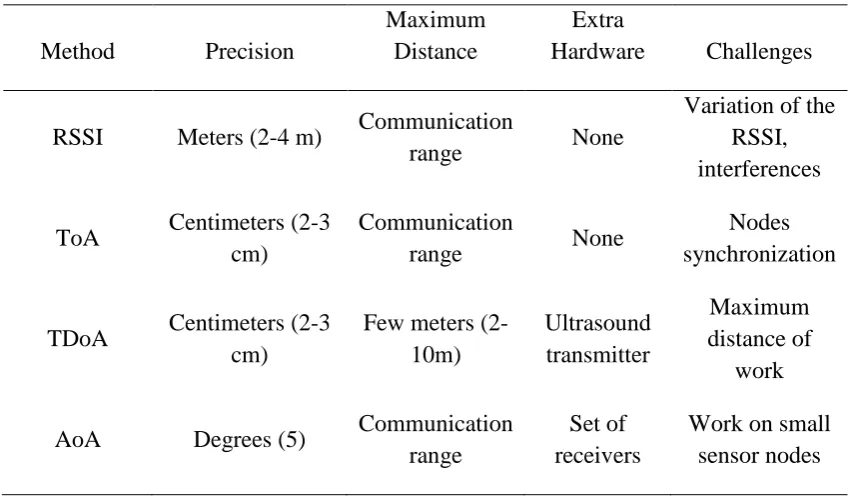
[image:23.595.106.533.361.610.2]In case of Wireless Sensor Network (WSN) there are many localization algorithms having different hardware requirements and varying accuracies (discussed in detail in chapter 2). Table 1.1 shows a comparison of precision, surveillance area range, extra hardware required and challenges in designing of different present localization methods (Boukerche, 2009).
Table 1.1: Comparison existing methods used for distance/angle estimation
Method Precision
Maximum Distance
Extra
Hardware Challenges
RSSI Meters (2-4 m) Communication
range None
Variation of the RSSI, interferences ToA Centimeters (2-3
cm)
Communication
range None
Nodes synchronization
TDoA Centimeters (2-3 cm)
Few meters (2-10m) Ultrasound transmitter Maximum distance of work AoA Degrees (5) Communication
range
Set of receivers
Work on small sensor nodes
4 surveillance area makes the system complicated, greater number of sensor nodes are used making these system suitable only in the case of limited surveillance area. In this research we have given an improved radar algorithm design which virtualizes reference tags and their information is kept in receiving nodes. Secondly number of sensor nodes are reduced to four (having one transmitting node and three receiving nodes), and Received Signal Strength Indicator (RSSI) tracking techniques are used in which there is no need for the intruder to carry a tag. Whenever intruder arrives in surveillance area it is monitored with RSSI localization technique and Virtual Reference Tags (VRTs) provide reference point closest to actual intruder location. This algorithm design has no synchronization problem (like in ToA) and has greater accuracy than RSSI.
1.2 Problem statement
WSN human intruder localization system are small in size and require less system resources compared to other localization radar systems. But there are also limitations in application and localization of WSN. Combination of different range estimation techniques with position estimation methods and localization algorithms gives us WSN designs with varying system properties and area of application. For human intruder localization WSN radar design previously presented (discussed in chapter 2, section 2.8) have a number of limitation in terms of less accuracy, hardware requirement, area of application, surveillance area range and additional tags requirement for localization.
For places which have large surveillance area like nuclear reactors, airports, hospitals, military bases etc require a system which can provide surveillance in longer ranges and have good accuracy. In previously presented system range of the systems differs with range estimation technique applied. In this research we have introduced VRTs which when virtually mapped over surveillance area increases WSN range (discussed in chapter 3, section 3.4).
5 On the other hand RSSI range estimation technique gives less accuracy but requires very no additional hardware assistance in actual implementation. In this research we have used RSSI range estimation technique and improved its performance with VRTs in terms of accuracy, cost and surveillance range.
Previously VRTs are used in RFID systems which used them to locate target carrying a reference tag. These systems have low surveillance are due to design of actual tags with virtual tags. This makes these systems application limited to indoor localization of known targets which carry tag. To overcome these limitations in our design we have virtualized all reference tags and their information is kept at each receiver or at fusion center connecting three receivers (discussed in chapter 3, section 3.1).
Increasing technology in vehicles makes them faster, comfortable and easy to drive. But on the same time it makes drivers too comfortable and unaware of the ground situation on which they are driving. The National Highway Traffic Safety Administration (NHTSA) of USA estimates that 100,000 police-reported crashes each year (NHTSA., [On- line]. Available: http://www.nhtsa.dot.gov/). This results in an estimated 1550 deaths, 71,000 injuries, and $12.5 billion in monetary losses. Many systems are presented that detect drowsiness and assist driver by alerting. These systems use monitoring eyes, facial expression detection, yawning state detection, heart rate variability and other physical approaches (Ijaz Khan, 2013). The main drawback of these systems is that they lack in accuracy in many cases. For example, if driver wears sun glasses eyes monitoring fails. In yawning detection if driver puts hand in front of his mouth while driving, yawning state cannot be detected and every person has his own facial features so having system suitable to extract all types of features is difficult (Omidyeganeh et al., 2011; Weiwei et al., 2010; Abtahi et al., 2011; Hariri et al., 2011).
6 the radar systems presented as collision prevention assistant in vehicles. Their size and cost contradicts with implementation in compact and low budget vehicles (Dickmann et al., 2012).
This research presents a solution to this problem by presenting a proposed radar design which can provide surveillance around the vehicle to its driver, assisting the driver to drive safely. The design uses UWB technologies over a WSN consisting of four sensor nodes. The localization algorithm of WSN uses ToA, AoA and RSSI information to locate position of other vehicles in surveillance area.
1.3 Objectives of the Study
The objectives of this project are:
(i) Design a WSN algorithm by using RSSI position estimation technique and modify with VRTs.
(ii) Design VRTs as clutter removal technique for objects other then target in surveillance area.
(iii) Propose a WSN radar application in automobiles as road safety feature.
1.4 Scope of the study
7 accuracy of WSN radar. Greater number of VRTs result in greater accuracy but on the same time it increases system hardware requirement in actual implementation.
1.5 Aim of the study
The aim of this research is to develop an algorithm of UWB radar localization system that can extract the information from target reflected signal and using that information can locate target location accurately. Also design the algorithm that can remove clutters created by different object other than target in surveillance area. Further, use the same algorithm with some modification to design road surveillance system for vehicles.
1.6 Significance of the Study
8 1.7 Novelty
In this research we have introduced reference tagging concept in UWB radar localization algorithms. Reference tags (previously used in RFID) are virtualized to assist in range estimation technique. RSSI range estimation technique is used with VRTs mapped over surveillance area. This has increased accuracy of RSSI from 2-4 m to 0.2-0.4m.
1.8 Project Schedule
The full project schedule is given in APPENDIX A table A.1.
1.9 Outline of the Thesis
The main parts of this thesis presents hybrid intruder localization algorithm for WSN which is discussed, analyzed and compared with other co-existing algorithms.
The remainder of this thesis is structured as follows:
Chapter 2 - Literature Review This chapter shows details about localization systems from multistatic radar designs to complex WSN systems. Further, WSN components which are range estimation techniques, position computation method and localization algorithms are explained and compared. Lastly intruder localization systems presented by different authors closest to our design are given with their system design, accuracy and limitations.
Chapter 3 - Methodology Presents the system design which uses three receivers and
one transmitter. Also this chapter shows how VRTs are virtually mapped over surveillance area and what information each VRT has for a particular location. The system design flowchart is also given in this chapter. Chapter 3 also describes proposed WSN application in automobiles.
9 introduced in surveillance area of 10x10m with 100 VRTs. For moving target NS2 simulator is used and nine different cases intruder localization and tracking is simulated with varying number of VRTs.
2CHAPTER 2
LITERATURE REVIEW
This chapter presents detailed description of related terms, methods and algorithms which are either used or are related to this research project. It starts by giving introduction to radar technology and its types namely monostatic, bistatic and multistatic radar. After this, UWB technology is discussed in details with its pros and cons and why UWB frequencies are used in this research project. WSNs being an important part of the research are extensively defined and discussed. With their basic system components and system requirements, their applications in different aspects are also given.
Localization algorithms (a part of WSN component) are the key focus of this research. This chapter gives a detailed review of the commonly used WSN localization algorithms which are ToA, RSSI, TDoA and AoA. Whenever the system nodes have enough information, they need to calculate target‟s position. To calculate position of target, the system can use one of these methods which are discussed in section 2.6. There are several methods which include trilateration, multilateration, triangulation, probabilistic approaches, bounding box, and the central position.
11
2.1 RADAR
According to Merrill l. Skolnik (Skolnik, 1990) The basic concept of radar is relatively simple even though in many instances its practical implementation is not. Radar operates by radiating electromagnetic energy and detecting the echo returned from reflecting objects (targets). The nature of the echo signal provides information about the target. The range, or distance, to the target is found from the time it takes for the radiated energy to travel to the target and back. Based on the number of transmitter and receiver, radars can be differentiated into three categories which are: (i) Monostatic radar
(ii) Bistatic radar (iii) Multistatic radar
2.1.1 Monostatic radar
12
Figure 2.1: Simple block diagram of a monostatic radar system by Merrill l. Skolnik
2.1.2 Bistatic radar
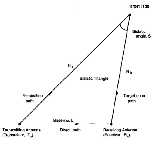
Bistatic radar is defined as a radar that uses antennas at different locations for transmission and reception (IEEE, 1982). Nicholas J. Willis explains the concept of bistatic radar as, a transmitting antenna is placed at one site and a receiving antenna is placed at a second site, separated by a distance L, called the baseline range or simply baseline. The target is located at a third site. Any of the sites can be on the earth, airborne, or in space, and may be stationary or moving with respect to the earth. Figure 2.2 shows Nicholas J. Willis presented bistatic radar geometry and typical requirements for bistatic radar operation.
13
Figure 2.2: Bistatic radar geometry by Nicholas J. Willis
2.1.3 Multistatic radar
14
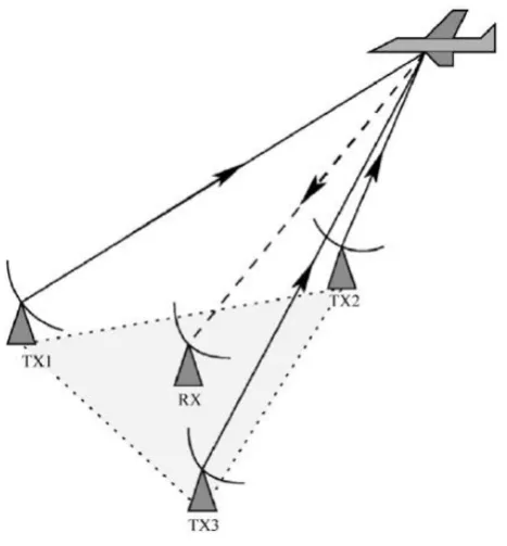
Figure 2.3: Multistatic radar with three transmitters and one receiver (Amanipour &Olfat, 2011)
Most detailed work done on multistatic radar is by Chernyak in 1998 (Chernyak, 1998). In his work first he defines multistatic radars with some of its characteristic followed by listed pros and cons of the system. Then he describes historical background and military functions and usage. Detection algorithms for target detection are discussed in chapter 2 of his book(Chernyak, 1998). Localization algorithms vary in the context of transmitter-receiver pair's information sharing within a surveillance area. Localziation algorithms, are discussed in chapter 3 of his book(Chernyak, 1998) followed by how they can be used in most efficient way for maximum outcome in different scenarios. This work is inclusive and provides extensive information about multistatic radar to the readers.
2.2 Ultra Wide Band (UWB)
15 April 2002). Where as in Europe a signal is UWB if its bandwidth is greater than 50MHz (Communities, February 2007).
The power spectral density of UWB systems is generally considered to be extremely low, especially for communication applications. The power spectral density (PSD) is defined as (Ghavami et al., 2004) :
B P
PSD (W/Hz) (2.1)
where,
P : power transmitted in watts (W). B : bandwidth of the signal in hertz (Hz).
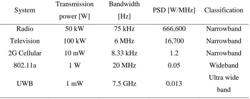
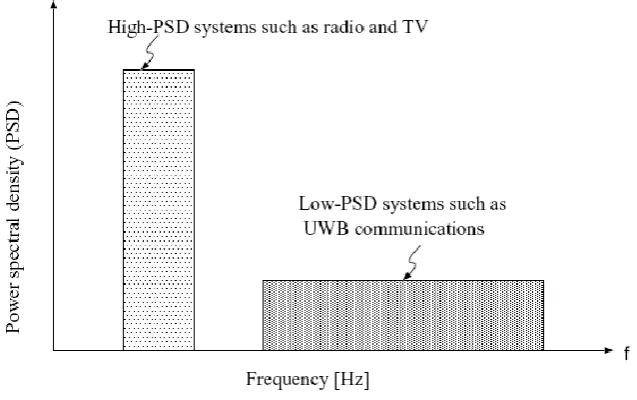
[image:35.595.108.532.419.587.2]Previously only narrow band frequencies were used which increased PSD whereas in UWB PSD is kept very low. Table 2.1 shows a comparison transmitted power, bandwidth and PSD of some commonly used wireless broadcast systems.
Table 2.1: A comparison of PSD of commonly used broadcast systems (Ghavami et al., 2004)
System Transmission power [W]
Bandwidth
[Hz] PSD [W/MHz] Classification
Radio 50 kW 75 kHz 666,600 Narrowband
Television 100 kW 6 MHz 16,700 Narrowband
2G Cellular 10 mW 8.33 kHz 1.2 Narrowband
802.11a 1 W 20 MHz 0.05 Wideband
UWB 1 mW 7.5 GHz 0.013 Ultra wide
band
16
Figure 2.4: Low-energy density and high-energy density systems (Ghavami et al., 2004)
2.2.1 Advantages of using UWB technologies
The advantages of using UWB technologies, but limited to are (Enrico Paolini, 2008):
(i) Low power consumption. (ii) High accuracy (centimeter).
(iii) Positioning can also be done in indoor environments. (iv) Low probability of interception (high security). (v) High data rates
(vi) Low equipment cost (vii) Multipath immunity
17 2.3 Wireless Sensor Network (WSN)
A wireless sensor network is composed of a number of wireless devices which are able to take environmental measures in a given surveillance area. These wireless sensors transmit their information to an application system where which make decision based on the information they have received. WSN are considered as one of the most technologies for the twenty- first century (Jun Zheng, 2009). Huge development is being made on the design and deployment issues of WSNs and significant advances are done in application and algorithm of WSNs. It is suspected that in coming future WSNs will be a part of most of daily use items and play a significant role in military fields.
2.3.1 Network characteristics
Generally a WSN is composed of a number of sensor nodes which are designed in such a way that they can perform multiple function on the same time while keeping their cost and power consumption low. These nodes are designed with sensors, microprocessors and transceivers giving them the ability to sense the situation, process the information and them communicate the results with system. They accomplish inter-communication by using a wireless channel and share their gathered sensor information to make a system that can monitor environment, light sound, humidity, or intruders with specific sizes and shapes. According to Jun Zheng WSNs have the following uniqueness and limitations when compared with other wireless networks (Jun Zheng, 2009):
(i) Dense Node Deployment. Sensor nodes are usually densely deployed in a field of interest. The number of sensor nodes in a sensor network can be several orders of magnitude.
(ii) Battery - Powered Sensor Nodes. Sensor nodes are usually powered by battery. In most situations, they are deployed in a harsh or hostile environment, where it is very difficult or even impossible to change or recharge the batteries.
18 (iv) Self - Configurable. Sensor nodes are usually randomly deployed without careful planning and engineering. Once deployed, sensor nodes have to autonomously configure themselves into a communication network.
(v) Application Specific. Sensor networks are application specific. A network is usually designed and deployed for a specific application. The design requirements of a network change with its application.
(vi) Unreliable Sensor Nodes. Sensor nodes are usually deployed in harsh or hostile environments and operate without attendance. They are prone to physical damages or failures. Frequent Topology Change. Network topology changes frequently due to node failure, damage, addition, energy depletion, or channel fading.
(vii) No Global Identification. Due to the large number of sensor nodes, it is usually not possible to build a global addressing scheme for a sensor network because it would introduce a high overhead for the identification maintenance.
2.3.2 Wireless sensor network applications
WSN have a vast scope of application that proposed as well as actually implemented. These applications include the fields of military, environmental and medical. Keeping in mind the advantages of WSNs over wired networks this section discusses some application of WSNs in different fields.
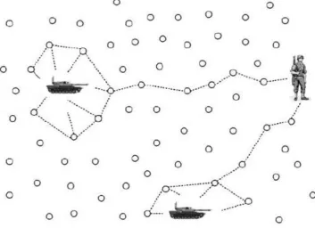
19 they sense some information. For example in figure 2.5 the sensor nodes are deployed over the surveillance area. When enemy tanks arrive their information is passed on through the surveillance area. The soldiers upon receiving information about enemy tanks movement path, can relocate themselves to counter the attack (Jun Zheng, 2009).
Figure 2.5: WSN in surveillance area for enemy target localization (Stojmenovic, 2005)
20 the information of location and severity of fire to the system which guides fire fighters to arrange a team based on severity of fire and send it to the location given by WSN system (Jun Zheng, 2009).
Figure 2.6: WSNs application as disaster monitoring system (Stojmenovic, 2005) (iii) Health applications: WSN provide a great application in medical for elderly
and patients in case of health care monitoring. This helps in reducing the shortage health care working in this field (Jafari et al., 2005). WSNs can be deployed over a patient‟s house which monitor the movement of patient while he moves around the house and guide him whenever doctors suspect any this wrong. This also helps in emergency cases like patients accidently fells down or has a heart attack etc. WSNs can also be integrated with wearable sensors and can send information about patient‟s physical conditions. This helps in making a record of the patient‟s body signatures over a specific medical treatment and can alert doctors if they sense something out of order (Trossen &Pavel, 2007).
21 video surveillance are difficult to install and cost more than WSN systems. WSNs can also provide surveillance in regions having fog of dust storms where video surveillance fails (Feng Zhao).
(v) Industrial applications: WSNs can be used in industries to monitor manufacturing equipment, process and products. The sensor network can identify if any equipment is broken or there is a faulty product. Also WSNs can be used to monitor workers giving information of their location and the work they are doing.
(vi) Intelligent housing: WSNs can provide a more comforting, convenient and time saving lifestyle to its users. These systems can monitor house temperature according to the user requirement and send its information to user through internet. Water level and temperature of a swimming pool, cooking stove temperature, quantity of food items in refrigerator and microwave oven can also be controlled using WSNs (Herring &Kaplan, 2000). TV, DVD and CD players can also be monitored and controlled based on the requirement of all the family members.
2.3.3 Wireless sensor network design objectives
Different application makes diversity in designs of WSNs based on the ground situation for which they are being designed. This makes WSNs complicated to propose and general design objectives. But some aspects of all WSNs are common can we can say they are the key focus in a general WSN. These design objectives are (Jun Zheng, 2009):
(i) Node size. (ii) Node cost.
(iii) Power consumption.
(iv) Configuration in a network. (v) Scalable number of nodes. (vi) Adaptive to changes.
(vii) Reliable information delivery. (viii) Secure.
22 2.4 Localization system in wireless sensor networks
The locations of nodes are not predesigned, which can cause huge amount of error in information the sensors pass back to the system. In order to remove this error location of node needs to be calculated. This is done by using localization systems. In WSNs sensor node monitor a given surveillance area and send their information back to system where the information of these sensor nodes are merged to calculate the findings and it becomes important to find out from which node this information has arrived. Since WSNs have vast applications and their design vary from each other so having localization system requires some properties which it need to fulfill. Some of these properties are:
(i) The localization system should fit in all type of infrastructures and automatically organize itself within the WSN.
(ii) The system should be fast and robustly process the information which is gathered by sensor nodes.
(iii) The system must be designed to tackle any amount of sensor nodes.
(iv) System efficiency should be high such that it utilize all the available resources
The localization systems can be divided into three major components namely range estimation, position computation and localization algorithms (briefly described in chapter 1).
2.5 Range estimation
Range estimation is done by calculating angle or distance between nodes. Range estimation is one of the most important aspects of localization system because its information is then used by localization algorithm to locate the target. There are different methods that can be used to calculate angle or distance between nodes. They differ in accuracy, cost, hardware, power consumption and processing time. The commonly used methods are:
23 2.5.1 Received Signal Strength Indicator (RSSI)
[image:43.595.170.466.383.529.2]The strength of signal received by the node is used to measure its distance from signal source in RSSI. The main disadvantage is in actual environment the signal gets interrupted by noise, clutters and antenna type, causing high inaccuracy in localization. The strength of signal received by the node is used to measure its distance from signal source. Greater the distance, lower the signal strength when it arrives to node. The signal strength weakens as the inverse of square distance, theoretically. The disadvantage is that in actual environment the signal gets interrupted by noise, clutters and antenna type, causing high inaccuracy in localization. An error of 2 to 3 meters is shown in surveillance area communication range of 10 meters through experimentation (Savvides et al., 2001). Figure 2.7 shows a transmitting node which is transmitting a signal which gradually loses its signal strength.
Figure 2.7: Decreasing signal transmitted by a transmitting node. The signal is send with specific signal strength which decreases as the square of distance. In real world
different other factors also contribute in decreasing signal strength (Boukerche, 2009)
In case of controlled environment and simulation RSSI show conceivable results but in actual scenario their design is still doubtable(Chengdu et al., 2003). But considering the low cost surveillance systems offered by RSSI it becomes impossible to completely ignore RSSI method.
24 system with known parameters (Friis, 1946). Equation 2.2 represents Friis formula to calculate received signal strength in ideal condition.
d
L
G
G
P
d
P
r a t t r2 2 2
4
)
(
(2.2)Where,
r
P
: Received signal strengtht
P
: Transmitted signal strengthr
G
: Receiver antenna gaint
G
: Transmitter antenna gain
: Wavelength of transmitted signald
: Distance between nodesL
: System lossIn 1996 Theodore extended equation 2.2 while considering signal reflection from ground (Rappaport, 1996). Equation 2.3 represents Theodore‟s equation which can be used to calculate received signal strength while considering signal reflections from the ground.
L
d
h
h
G
G
P
d
P
r b t t 4r t r2 2
)
(
(2.3)Where,
2 t
h
: Height of transmitter antenna2 r
h
: Height of receiver antenna2.5.2 Time/Difference of Arrival (ToA/TDoA)
REFERENCES
Abdullah, H., Khan, I., &Shamian, M.(2013a), Clutter Removal Technique Using Virtual Reference Tags for Intruder Localization in Ultra Wide Band Radar Network, International Journal of Engineering and Applied Sciences, EAAS. Abdullah, H., Khan, I., &Shamian, M. "Improved Received Signal Strength Indicator
Localization Algorithm with Virtual Reference Tags." Prosiding Seminar Kebangsaan Aplikasi Sains dan Matematik 2013 (SKASM2013). Ed. Print. Abdullah, H., Khan, I., &Shamian, M.(2013c), Improved Uwb Wireless Sensor
Network Algorithm for Human Intruder Localization, Research Journal of Applied Sciences, Engineering and Technology. © Maxwell Scientific Organization.
Abdullah, H., Khan, I., &Shamian, M. "Proposed Wireless Sensor Network in Vehicles for Road Surveillance." IEEE conference on system, process and control (ICSPC 2013). Ed.: IEEE Xplore. Print.
Abdullah, H., Khan, I., &Shamian, M.(2012), Ultra Wide Band Localization and Tracking Hybrid Technique Using Vrts, International Journal of Integrated Engineering,UTHM.
Abtahi, S., Hariri, B., &Shirmohammadi, S. (2011), Driver Drowsiness Monitoring Based on Yawning Detection, proceeding, Instrumentation and Measurement Technology Conference (I2MTC), 2011 IEEE, 1-4.
Ahmadi, R., Jahangiry, A., Babaie, S., &Kordlar, M. (2012), Localization in Wireless Sensor Network by Using Mobile Stations, proceeding, Biomedical and Health Informatics (BHI), 2012 IEEE-EMBS International Conference on, 277-80.
Albowicz, J., Chen, A., &Lixia, Z. (2001), Recursive Position Estimation in Sensor Networks, proceeding, Network Protocols, 2001. Ninth International Conference on, 35-41.
Amanipour, V., &Olfat, A.(2011), Cfar Detection for Multistatic Radar, Signal Processing, 28-37.
Bahl, P., &Padmanabhan, V. N. (2000), Radar: An in-Building Rf-Based User Location and Tracking System, proceeding, INFOCOM 2000. Nineteenth Annual Joint Conference of the IEEE Computer and Communications Societies. Proceedings. IEEE, 775-84 vol.2.
Boukerche, A.(2009), Algorithms and Protocols for Wireless Sensor Networks, John Wiley & Sons, Canada.
Brilon, R. J. T. a. W.(Publications and Products, Office of Highway Policy Information, Federal Highway Administration), Unsignalized Intersection Theory.
110
Annual International Conference on Mobile Computing and Networking. Ed.: ACM press. Print.
Chernyak, V. S.(1998), Fundamentals of Multisite Radar System, Gordon and Breach Science Publishers.
ChulYoung, P., DaeHeon, P., JangWoo, P., YangSun, L., &Youngeun, A. (2010), Localization Algorithm Design and Implementation to Utilization Rssi and Aoa of Zigbee, proceeding, Future Information Technology (FutureTech), 2010 5th International Conference on, 1-4.
Coelingh, E., Eidehall, A., &Bengtsson, M. (2010), Collision Warning with Full Auto Brake and Pedestrian Detection - a Practical Example of Automatic Emergency Braking, proceeding, Intelligent Transportation Systems (ITSC), 2010 13th International IEEE Conference on, 155-60.
Commission, F. C.(April 2002), Revision of Part 15 of the Commission‟s Rules Regarding Ultra-Wideband Transmission Systems, First Report and Order (Et Docket 98-153).
Communities, C. o. t. E.(February 2007), Commission Decision of 21 February 2007 on Allowing the Use of the Radio Spectrum for Equipment Using Ultra-Wideband Technology in a Harmonised Manner in the Community (2007/131/Ec), Official Journal of the European Union.
de Oliveira, H. A. B., Nakamura, E. F., Loureiro, A. A. F., &Boukerche, A. (2005), Directed Position Estimation: A Recursive Localization Approach for Wireless Sensor Networks, proceeding, Computer Communications and Networks, 2005. ICCCN 2005. Proceedings. 14th International Conference on, 557-62.
Dickmann, J., Klappstein, J., Bloecher, H.-L., Muntzinger, M., &Meinel, H. (2012), Automotive Radar — “Quo Vadis?”, proceeding, Radar Conference (EuRAD), 2012 9th European, 18-21.
Ding, N., Tan, G., Ma, H., Lin, M., &Shang, Y. (2008), Low-Power Vehicle Speed Estimation Algorithm Based on Wsn, proceeding, Intelligent Transportation Systems, 2008. ITSC 2008. 11th International IEEE Conference on, 1015-20. Doherty, L., pister, K. S. J., &El Ghaoui, L. (2001), Convex Position Estimation in
Wireless Sensor Networks, proceeding, INFOCOM 2001. Twentieth Annual Joint Conference of the IEEE Computer and Communications Societies. Proceedings. IEEE, 1655-63 vol.3.
Doughty, S. R. (2008), Development and Performance Evaluation of a Multistatic Radar System, University of London., Doctor of Philosophy.
Dybdal, R. B.(1987), Radar Cross Section Measurements, Proceedings of the IEEE, 498-516.
El-Rabbany, A.(2002), Introduction of Global Positioning System, British Library Cataloguing in Publication Data, 685 Canton Street,Norwood, MA 02062. Enrico Paolini, A. G. a. M. C.(2008), Localization Capability of Cooperative
Anti-Intruder Radar Systems, EURASIP Journal on Advances in Signal Processing.
Ergut, S., Rao, R. R., Dural, O., &Sahinoglu, Z. (2008), Localization Via Tdoa in a Uwb Sensor Network Using Neural Networks, proceeding, Communications, 2008. ICC '08. IEEE International Conference on, 2398-403.
111
and Networking Symposia, 2008. FGCNS '08. Second International Conference on, 49-54.
F., H., Oliveira, E. F., Nakamura, A. A. F., Loureiro., &Boukerche, A. "Error Analysis of Localization Systems for Sensor Networks." In Proceedings of the 13th ACM International Symposium on Geographic Information Systems (GIS ’05). Ed.: ACM Press, New York. Print.
Farina, A.(1987), Optimised Radar Processors, Peter Peregrinus Ltd, London.
Feng Zhao, L. J. G.(Wireless Sensor Networks: An Information Processing Approach, Morgan Kaufmann Publishers.
Friis, H. T.(1946), A Note on a Simple Transmission Formula, Proceedings of the IRE, 254-56.
Galati, G.(1993), Advanced Radar Techniques and Systems, Peter Peregrinus Ltd, London.
Ghavami, M., Michael, L., &Kohno, R.(2004), Ultra Wideband Signals and Systems in Communication Engineering, John Wiley & Sons, Ltd.
Hariri, B., Abtahi, S., Shirmohammadi, S., &Martel, L. (2011), Demo: Vision Based Smart in-Car Camera System for Driver Yawning Detection, proceeding, Distributed Smart Cameras (ICDSC), 2011 Fifth ACM/IEEE International Conference on, 1-2.
Herring, C., &Kaplan, S.(2000), Component-Based Software Systems for Smart Environments, Personal Communications, IEEE, 60-61.
Hofmann-Wellenhof, B., Lichtenegger, H., &Collins, J.(2001), Global Positioning System, Springer-Verlag, Berlin.
Hofmann-Wellenhof, B., Lichtenegger, H., Collins, J.(2001), Global Positioning System, Springer-Verlag, Berlin.
Huseyin Arslan, Z. N. C., Maria-Gabriella Di Benedetto.(2012), Ultra Wide Band Wirelless Communication, WILEY-INTERSCIENCE, New Jersy.
IEEE.(1982), Ieee Standard Radar Definitions,, IEEE Std.
Ijaz Khan, H. A., Mohd Shamian Bin Zainal.(2013), Efficient Fatigue Detection System as Road Safety Feature for Vehicle Research Journal of Applied Sciences, Engineering and Technology © Maxwell Scientific Organization. Jafari, R., Encarnacao, A., Zahoory, A., Dabiri, F., Noshadi, H., &Sarrafzadeh, M.
(2005), Wireless Sensor Networks for Health Monitoring, proceeding, Mobile and Ubiquitous Systems: Networking and Services, 2005. MobiQuitous 2005. The Second Annual International Conference on, 479-81.
Jun Zheng, A. J.(2009), Wireless Sensor Networks:A Networking Perspective, Wiley-IEEE Press.
Junhuai, L., Rui, Q., Yile, W., &Feng, W.(2011), An Rfid Location Model Based on Virtual Reference Tag Space, Journal of Computational Information Systems. Kunz, L. L. a. T. (October 2007), Cooperative Node Localization for Tactical Wireless Sensor Networks, proceeding, in Proceedings of the IEEE Military Communications Conference (MILCOM ’07).
Liang, H. D. L. a. Q. "Collaborative Multi-Target Detection in Radar Sensor Networks." in Proceedings of the IEEE Military Communications Conference (MILCOM ’07). Ed. Print.
M. Ghavami, L. B. M. a. R. K.(2004), Ultra Wideband Signals and Systems in Communication Engineering, John Wiley & Sons, Ltd.
112
Nag, S., &Barnes, M. (2003), A Moving Target Detection Filter for an Ultra-Wideband Radar, proceeding, Radar Conference, 2003. Proceedings of the 2003 IEEE, 147-53.
Ng, W. W. Y., Hai-Lan, D., Chan, P. P. K., &Yeung, D. S. (2011), Efficiency of Applying Virtual Reference Tag to Neural Network Based Rfid Indoor Positioning Method, proceeding, Machine Learning and Cybernetics (ICMLC), 2011 International Conference on, 447-53.
NHTSA.([On- line]. Available: http://www.nhtsa.dot.gov/), Drowsly driver detection and warning system for commercial vehicle drivers: Field proportional test design, analysis, and progress. National Highway Traffic Safety Administration,Washington.
Ni, L. M., Dian, Z., &Souryal, M. R.(2011), Rfid-Based Localization and Tracking Technologies, Wireless Communications, IEEE, 45-51.
Nicolaescu, I., &Oroian, T. (2001), Radar Cross Section, proceeding, Telecommunications in Modern Satellite, Cable and Broadcasting Service, 2001. TELSIKS 2001. 5th International Conference on, 65-68 vol.1.
Niculescu, D., &Nath, B. (2001), Ad Hoc Positioning System (Aps), proceeding, Global Telecommunications Conference, 2001. GLOBECOM '01. IEEE, 2926-31 vol.5.
Niculescu, D., &Nath, B. (2003), Ad Hoc Positioning System (Aps) Using Aoa, proceeding, INFOCOM 2003. Twenty-Second Annual Joint Conference of the IEEE Computer and Communications. IEEE Societies, 1734-43 vol.3.
Nissanka B., Anit C., &B., H. "The Cricket Location-Support System." 6th ACM International Conference on Mobile Computing and Networking. Ed. Print. Nissanka B. Priyantha, A. C., and Hari Balakrishnan. "The Cricket Location-Support
System." 6th ACM International Conference on Mobile Computing and Networking. Ed. Print.
Nissanka Bodhi Priyantha, A. K. M., Hari Balakrishnan, Seth Teller. "The Cricket Compass for Context-Aware Mobile Applications." 7th ACM MOBICOM. Ed. Print.
Omidyeganeh, M., Javadtalab, A., &Shirmohammadi, S. (2011), Intelligent Driver Drowsiness Detection through Fusion of Yawning and Eye Closure, proceeding, Virtual Environments Human-Computer Interfaces and Measurement Systems (VECIMS), 2011 IEEE International Conference on, 1-6.
Pritchard, D.(1989), The Radar War : Germany's Pioneering Achievement 1904-45, Germany.
Rappaport, T. S.(1996), Wireless Communication Principles and Practice, Prentice Hall, NJ.
Safa, H., &Yassine, F. (2012), Localization in Large Scale Wireless Sensor Networks, proceeding, Telecommunications (ICT), 2012 19th International Conference on, 1-6.
Sakamoto, T.(2005), Nonparametric Imaging Algorithms for Uwb Pulse Radars, Ph.D. dissertation,Kyoto University, Kyoto, Japan.
Sangho, L., Eunchan, K., Chungsan, K., &Kiseon, K.(2009), Localization with a Mobile Beacon Based on Geometric Constraints in Wireless Sensor Networks, Wireless Communications, IEEE Transactions on, 5801-05.
113
Savvides, A., Han, C., &Strivastava, M.(2001), Dynamic Fine-Grained Localization in Ad-Hoc Networks of Sensors, 7th ACM/IEEE International Conference on Mobile Computing and Networking, 166-79.
Sichitiu, M. L., &Ramadurai, V. (2004), Localization of Wireless Sensor Networks with a Mobile Beacon, proceeding, Mobile Ad-hoc and Sensor Systems, 2004 IEEE International Conference on, 174-83.
Skolnik, M. "Radar Handbook." second ed: McGraw-Hill, 1990. 1-30. Print.
Skolnik, M. I.( March 1961), An Analysis of Bistatic Radar, IRE Trans. Aerospace and Navigational Electronics, , 19-27.
Skolnik, M. I.(1980), Introduction to Radar Systems,, McGraw-Hill, New York. Stojmenovic, I.(2005), Handbook of Sensor Networks Algorithms and Architectures,
A JOHN WILEY & SONS, INC, Canada.
Swords, S. S.(1996), Technical History of the Beginnings of Radar, The Institution of Engineering and Technology, London.
Tait, P.(2005), Introduction to Radar Target Recognition The institution of electrical engineering, united kingdom.
Tian He, C. H., Brian M. Blum, John A. Stankovic, Tarek Abdelzaher. "Range-Free Localization Schemes for Large Scale Sensor Networks." Proceedings of the 9th annual international conference on Mobile computing and networking. Ed. Print.
Trossen, D., &Pavel, D.(2007), Sensor Networks, Wearable Computing, and Healthcare Applications, Pervasive Computing, IEEE, 58-61.
Viani, F., Rocca, P., Lizzi, L., Rocca, M., Benedetti, G., &Massa, A. (2011), Wsn-Based Early Alert System for Preventing Wildlife-Vehicle Collisions in Alps Regions, proceeding, Antennas and Propagation in Wireless Communications (APWC), 2011 IEEE-APS Topical Conference on, 106-09.
Weile, Z., Qinye, Y., Hongyang, C., Feifei, G., &Ansari, N.(2013), Distributed Angle Estimation for Localization in Wireless Sensor Networks, Wireless Communications, IEEE Transactions on, 527-37.
Weiwei, L., Haixin, S., &Weijie, S. (2010), Driver Fatigue Detection through Pupil Detection and Yawing Analysis, proceeding, Bioinformatics and Biomedical Technology (ICBBT), 2010 International Conference on, 404-07.
Whitehouse, K. (2002), The Design of Calamari: An Ad Hoc Localization System for Sensor Networks, University of California at Berkeley, M.S.