Turin Networks Inc.
TransNav Management System
Documentation
Release TN4.0.x
Publication Date: January 2008
Document Number: 800-0007-TN40 Rev. B
Graphical User Interface
Reference Guide
FCC Compliance
This equipment has been tested and found to comply with the limits for a Class A digital device, pursuant to Part 15 of the FCC Rules. This equipment generates, uses, and can radiate radio frequency energy and, if not installed and used in accordance with the installation instructions may cause harmful interference to radio communications.
Canadian Compliance
This Class A digital apparatus meets all requirements of the Canadian Interference-Causing Equipment Regulations. Cet appareil numérique de la classe A respects toutes les exigences du Règlement sur le matériel brouilleur du Canada.
Japanese Compliance
This is a Class A product based on the standard of the Voluntary Control Council for Interference by Information Technology Equipment (VCCI). If this equipment is used in a domestic environment, radio disturbance may occur, in which case, the user may be required to take corrective actions.
International Declaration of Conformity
We, Turin Networks, Inc. declare under our sole responsibility that the Traverse platform (models: Traverse 2000, Traverse 1600, and Traverse 600) to which this declaration relates, is in conformity with the following standards:
EMC Standards
EN55022 EN55024 CISPR-22
Safety Standards
EN60950 CSA 22.2 No. 60950, ASINZS 3260
IEC 60950 Third Edition. Compliant with all CB scheme member country deviations.
Following the provisions of the EMC Directive 89/336/EEC of the Council of the European Union. Copyright © 2008 Turin Networks, Inc.
All rights reserved. This document contains proprietary and confidential information of Turin Networks, Inc., and may not be used, reproduced, or distributed except as authorized by Turin Networks. No part of this publication may be reproduced in any form or by any means or used to make any derivative work (such as translation, transformation or adaptation) without written permission from Turin Networks, Inc.
Turin Networks reserves the right to revise this publication and to make changes in content from time to time without obligation on the part of Turin Networks to provide notification of such revision or change. Turin Networks may make improvements or changes in the product(s) described in this manual at any time. Turin Networks Trademarks
Turin Networks, the Turin Networks logo, Traverse, TraverseEdge, TransAccess, TransNav, and Creating The Broadband Edge are trademarks of Turin Networks, Inc. or its affiliates in the United States and other countries. All other trademarks, service marks, product names, or brand names mentioned in this document are the property of their respective owners.
Government Use
Use, duplication, or disclosure by the U.S. Government is subject to restrictions as set forth in FAR 12.212 (Commercial Computer Software-Restricted Rights) and DFAR 227.7202 (Rights in Technical Data and Computer Software), as applicable.
T
RANS
N
AV
M
ANAGEMENT
S
YSTEM
GUI R
EFERENCE
G
UIDE
Contents
About this Document . . . v
Section 1 Installation and Overview
Chapter 1
Installation for Windows Workstations. . . 1-1 Chapter 2
Installation for Solaris Workstations . . . 1-9 Chapter 3
Starting the Graphical User Interface . . . 1-17 Chapter 4
Graphical User Interface General Description. . . 1-35
Section 2 Administrative Tasks
Chapter 1
Managing Server Security . . . 2-1 Chapter 2
Managing Node Security . . . 2-11 Chapter 3 User Preferences . . . 2-15 Chapter 4 Administrative Tasks . . . 2-25 Section 3 Network Chapter 1
Creating and Deleting Equipment Using Preprovisioning . . . 3-1 Chapter 2
Network Auto Discovery . . . 3-19 Chapter 3
Node Timing . . . 3-21 Chapter 4
DCC Tunnels. . . 3-33 Chapter 5
Configuring IP Quality of Service . . . 3-35
Section 4 Protection Switching
Chapter 1
BLSR and MS-SPRing Protection Groups . . . 4-1 Chapter 2
UPSR and SNCP Ring Protection Groups . . . 4-9 Chapter 3
Chapter 4
1+1 MSP/APS Protection Groups . . . 4-21 Chapter 5
1+1 Path Protection Groups . . . 4-27 Chapter 6
Carrier Ethernet Protection Pair . . . 4-29 Chapter 7
1+1 Optimized Protection Groups . . . 4-33
Section 5 Equipment Chapter 1 Common Equipment . . . 5-1 Chapter 2 SONET Equipment . . . 5-7 Chapter 3 SDH Equipment . . . 5-31 Chapter 4 Ethernet Equipment . . . 5-49 Chapter 5 TransAccess 200 Mux . . . 5-73 Chapter 6 TraverseEdge 50 (TE-50) . . . 5-79 Section 6 Services Chapter 1
Service Creation Concepts . . . 6-1 Chapter 2 SONET Services . . . 6-13 Chapter 3 SDH Services . . . 6-27 Chapter 4 Ethernet Services . . . 6-41 Chapter 5 VC-Bundles . . . 6-53 Chapter 6 Service Groups . . . 6-57 Chapter 7 Managing Services . . . 6-61 Chapter 8
Managing Service Paths . . . 6-71
Section 7 DCS Applications Chapter 1 DCS-384 Matrix Shelf . . . 7-1 Chapter 2 DCS-IO Shelf . . . 7-15 Chapter 3 DCS-96 Shelf. . . 7-23
Section 8 Maintenance and Testing Chapter 1 Performance Monitoring . . . 8-1 Chapter 2 Alarms . . . 8-11 Chapter 3 Events . . . 8-25 Chapter 4 Diagnostics . . . 8-37 Chapter 5 Test Access. . . 8-41 Chapter 6 Software Upgrades . . . 8-47 Section 9 Appendices Appendix A Service Endpoints . . . 9-1 Index. . . Index-1
GUI Guide [TN4.0.x] Document Description
About this Document
Introduction This description contains the following documentation topics:
• Traverse System Product Documentation, page v
• TraverseEdge System Product Documentation, page vi
• TransNav Management System Product Documentation, page vii
• Operations Documentation, page viii
• Information Mapping, page viii
• If You Need Help, page viii
• Calling for Repairs, page viii
Refer to “” to review the new and changed features for this release.
Traverse System Product Documentation
The Traverse®
system product documentation set includes the documents described in the table below.
Table 1 Traverse System Product Documentation
Document Description Target Audience
Traverse Product Overview
This document provides a detailed overview of the Traverse system. It also includes engineering and planning information.
Anyone who wants to understand the Traverse system and its applications. Traverse
Installation and Configuration
This document provides required equipment, tools, and step-by-step procedures for:
• Hardware installation
• Power cabling
• Network cabling
• Node power up
• Node start-up
Installers, field, and network engineers
Traverse Provisioning
This document provides step-by-step procedures for provisioning a network of Traverse nodes using the TransNav management system. See the TransNav Management System Product Documentation.
Network engineers, provisioning, and network operations center (NOC) personnel
TraverseEdge System Product Documentation
TraverseEdge System Product Documentation
The TraverseEdge™ 100 User Guide includes the sections described in the table below. Table 2 TraverseEdge 100 System Product Documentation
Section Description Target Audience
Product Overview This section provides a detailed overview of the TraverseEdge system.
Anyone who wants to understand the TraverseEdge system and its applications Description and
Specifications
This section includes engineering and planning information.
Field and network engineers Installation and
Configuration
This document identifies required equipment and tools and provides step-by-step procedures for:
• Hardware installation
• Power cabling
• Network cabling
• Node power up
• Node start-up
Installers, field, and network engineers
Provisioning the Network
This section provides step-by-step procedures for provisioning a TraverseEdge network using the TransNav management system. Also see the
TransNav Management System Product Documentation. Network engineers, provisioning, and network operations center (NOC) personnel Configuring Equipment
This section provides step-by-step procedures for configuring module and interface parameters of a TraverseEdge using the TransNav management system. Also see the TransNav Management System Product Documentation.
Network engineers, provisioning, and network operations center (NOC) personnel Creating TDM Services
This section provides step-by-step procedures for provisioning a TraverseEdge network using the TransNav management system. Also see the
TransNav Management System Product Documentation. Network engineers, provisioning, and network operations center (NOC) personnel Creating Ethernet Services
This section provides step-by-step procedures for provisioning a TraverseEdge network using the TransNav management system. See the TransNav Management System Product Documentation.
Network engineers, provisioning, and network operations center (NOC) personnel Appendices This section provides installation and provisioning
checklists, compliance information, and acronym descriptions.
Installers and anyone who wants reference information.
TransNav Management System Product Documentation TransNav Management System Product Documentation
The TransNav™ management system product documentation set includes the documents described in the table below.
Table 3 TransNav Management System Product Documentation
Document Description Target Audience
TransNav Management System Product Overview
This document provides a detailed overview of the TransNav management system.
This document includes hardware and software requirements for the management system. It also includes network management planning information.
Anyone who wants to understand the TransNav management system TransNav Management System Server Guide
This document describes the management server component of the management system and provides procedures and troubleshooting information for the server.
Field and network engineers, provisioning, and network operations center (NOC) personnel TransNav Management System GUI Guide
This document describes the graphical user interface including installation instructions and logon procedures.
This document describes every menu, window, and screen a user sees in the graphical user interface. TransNav
Management System CLI Guide
This document includes a quick reference to the command line interface (CLI). Also included are comprehensive lists of both the node-level and domain-level CLI commands.
TransNav Management System TL1 Guide
This document describes the syntax of the TL1 language in the TransNav environment.
This document also defines all input commands and expected responses for retrieval commands as well as autonomous messages that the system outputs due to internal system events.
Operations Documentation
Operations Documentation
The document below provides operations and maintenance information for Turin’s TransNav managed products.
Information Mapping
Traverse, TransNav, and TraverseEdge 100 system documentation uses the Information Mapping format which presents information in small units or blocks. The beginning of an information block is identified by a subject label in the left margin; the end is identified by a horizontal line. Subject labels allow the reader to scan the document and find a specific subject. Its objective is to make information easy for the reader to access, use, and remember.
Each procedure lists the equipment and tools and provides step-by-step instructions required to perform each task. Graphics are integrated into the procedures whenever possible.
If You Need Help
If you need assistance while working with Traverse products, contact the Turin Networks Technical Assistance Center (TAC):
• Inside the U.S., toll-free: 1-866-TURINET (1-866-887-4638)
• Outside the U.S.: 916-348-2105
• Online: www.turinnetworks.com/html/support_overview.htm
TAC is available 6:00AM to 6:00PM Pacific Time, Monday through Friday (business hours). When the TAC is closed, emergency service only is available on a callback basis. E-mail support (24-hour response) is also available through:
Calling for Repairs
If repair is necessary, call the Turin Repair Facility at 1-866-TURINET
(866-887-4638) for a Return Material Authorization (RMA) number before sending the unit. The RMA number must be prominently displayed on all equipment cartons. The Repair Facility is open from 6:00AM to 6:00PM Pacific Time, Monday through Friday. When calling from outside the United States, use the appropriate international access code, and then call 916-348-2105 to contact the Repair Facility.
Table 4 Operations Documentation
Document Description Target Audience
Node Operations and Maintenance
This document identifies required equipment and tools. It also provides step-by-step procedures for:
• Alarms and recommended actions
• Performance monitoring
• Equipment LED and status
• Diagnostics
• Test access (SONET network only)
• Routine maintenance
• Node software upgrades
• Node hardware upgrades
Field and network engineers
Calling for Repairs
When shipping equipment for repair, follow these steps:
1. Pack the unit securely.
2. Enclose a note describing the exact problem.
3. Enclose a copy of the invoice that verifies the warranty status.
4. Ship the unit PREPAID to the following address: Turin Networks, Inc.
Turin Repair Facility Attn: RMA # ________ 1415 North McDowell Blvd. Petaluma, CA 94954 USA
S
ECTION
1 I
NSTALLATION
AND
O
VERVIEW
SECTION 1OVERVIEW, INSTALLATION AND ADMINISTRATION
Contents
Chapter 1
Installation for Windows Workstations
Before You Install the GUI Application . . . 1-1 Configure Web Browser Settings for Internet Explorer . . . 1-2 Install the GUI Application on a Windows Workstation . . . 1-5 Uninstall the GUI from Windows Workstation . . . 1-7
Chapter 2
Installation for Solaris Workstations
Before You Install the GUI Application . . . 1-9 Configure Web Browser Settings for Netscape Navigator . . . 1-10 Configure Window Manager Settings for Solaris. . . 1-11 Install the GUI Application on a Solaris Workstation . . . 1-12 Uninstall the GUI from a Solaris Workstation . . . 1-15
Chapter 3
Starting the Graphical User Interface
Starting the GUI from the Management Server. . . 1-18 Starting the GUI Application on a Windows Platform . . . 1-19 Starting the GUI Application on a Solaris Platform . . . 1-21 User Login . . . 1-22
Chapter 4
Graphical User Interface General Description
Map View. . . 1-36 Shortcut Menus for Map View. . . 1-37 Traverse Shelf View . . . 1-39 Shortcut Menu for Shelf View . . . 1-40 TE-100 Shelf View. . . 1-43 Shortcut Menu for Shelf View . . . 1-44 GUI Menus . . . 1-45 File Menu. . . 1-46 View Menu. . . 1-46 Alarm Menu . . . 1-47 Events Menu . . . 1-47 Services Menu. . . 1-48 Service Groups Menu . . . 1-49 Admin Menu . . . 1-49 Provisioning Menu. . . 1-51 Help Menu . . . 1-51
TransNav GUI Guide, Section 1 Installation and Overview
GUI Conventions . . . 1-51 Scroll Bars . . . 1-51 Resizing Capabilities . . . 1-52
List of Figures
Figure 2-1 Internet Options Dialog Box, Advanced Tab . . . 1-2
Figure 2-2 Internet Options Dialog Box, Security Tab . . . 1-3
Figure 2-3 Internet Explorer Security Settings . . . 1-4
Figure 2-4 TransNav GUI Splash Screen . . . 1-5
Figure 2-5 Shelf Icon on Splash Screen . . . 1-6
Figure 2-6 Windows GUI Install Wizard . . . 1-6
Figure 2-7 Windows GUI Uninstall Wizard . . . 1-7
Figure 1-8 Netscape Navigator Preferences Dialog Box . . . 1-10
Figure 1-9 Solaris Style Manager—Window Dialog Box . . . 1-11
Figure 1-10 TransNav Management System Splash Screen . . . 1-12
Figure 1-11 Shelf Icon on Splash Screen . . . 1-13
Figure 1-12 Solaris Client—Save As Dialog Box . . . 1-13
Figure 1-13 Solaris Client—Download Dialog Box . . . 1-13
Figure 1-14 Solaris GUI Install Wizard . . . 1-14
Figure 1-15 Server Admin Application—Start GUI . . . 1-18
Figure 1-16 GUI Login Dialog Box . . . 1-18
Figure 1-17 Start Menu . . . 1-19
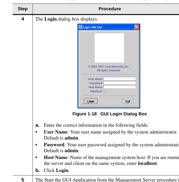
Figure 1-18 GUI Login Dialog Box . . . 1-20
Figure 1-19 GUI Login Dialog Box . . . 1-21
Figure 1-20 Login Dialog Box . . . 1-22
Figure 1-21 Login Dialog Box - Advanced Settings . . . 1-23
Figure 1-22 Map View . . . 1-36
Figure 1-23 Map View Shortcut Menu #1 . . . 1-37
Figure 1-24 Map View Shortcut Menu #2 . . . 1-38
Figure 1-25 Shelf View . . . 1-39
Figure 1-26 Shelf View Shortcut Menu #1 . . . 1-41
Figure 1-27 Shelf View Shortcut Menu #2 . . . 1-42
Figure 1-28 TraverseEdge 100 Shelf View . . . 1-43
Figure 1-29 Shelf View Shortcut Menu #1 . . . 1-44
Figure 1-30 Shelf View Shortcut Menu #2 . . . 1-45
Figure 1-31 File Menu. . . 1-46
Figure 1-32 View Menu . . . 1-46
Figure 1-33 Alarm Menu . . . 1-47
Figure 1-34 Events Menu . . . 1-47
Figure 1-35 Services Menu . . . 1-48
Figure 1-36 Services Groups Menu . . . 1-49
Figure 1-37 Admin Menu . . . 1-49
Figure 1-38 Provisioning Menu . . . 1-51
Figure 1-39 Help Menu . . . 1-51
TransNav GUI Guide, Section 1 Installation and Overview
List of Tables
Table 2-1 Before You Install the GUI application (Windows) . . . 1-1
Table 2-2 Set Web Browser Settings for Internet Explorer. . . 1-2
Table 2-3 Install GUI on a Windows Workstation . . . 1-5
Table 2-4 Uninstall GUI from Windows Workstation . . . 1-7
Table 1-5 Before You Install the GUI application (Solaris) . . . 1-9
Table 1-6 Set Web Browser Settings for Netscape Navigator . . . 1-10
Table 1-7 Install GUI on a Solaris Workstation . . . 1-12
Table 1-8 Uninstall GUI from Solaris Workstation. . . 1-15
Table 1-9 Start the GUI Application from the Management Server. . . 1-18
Table 1-10 Start the GUI Application on a Windows Platform. . . 1-19
SECTION 1 INSTALLATION AND OVERVIEW
Chapter 1
Installation for Windows Workstations
Introduction You can manage a network of Traverse and TraverseEdge 100 nodes using either a Solaris or a Windows 2000 Professional platform. This chapter includes the following procedures on how to install the graphical user interface (GUI) on a Windows platform:
• Before You Install the GUI Application, page 1-1
• Install the GUI Application on a Windows Workstation, page 1-6
• Uninstall the GUI from Windows Workstation, page 1-8
See Chapter 2—“Installation for Solaris Workstations,” page 1-9 for the procedures to install the GUI application on a Sun Solaris workstation.
Before You Install the GUI Application
To access the GUI on a computer other than the management server, install the GUI application onto the remote computer. Turin recommends installing the application directly onto the client workstation for faster initialization and operation and response time.
Before you install the management server software, understand the following requirements:
Table 1-1 Before You Install the GUI application (Windows)
Requirement Reference
GUI application requirements See the TransNav Management System Product Overview Guide, Section 2—Management System Planning,
Chapter 1—“TransNav Management System Requirements,” page 2-1
Windows configuration requirements for GUI application.
If this is the first time you are installing the TransNav system on the workstation, use the procedure Configure Web Browser Settings for Internet Explorer, page 1-2 to configure the environment.
Support for Citrix server. Turin supports using the GUI application on a Citrix server. Starting the GUI application See Section 1—Installation and Overview, Chapter 3—“Starting
the Graphical User Interface,” page 1-17 for detailed procedures on starting the GUI application
TransNav GUI Guide, Section 1: Installation and Overview
Configure Web Browser Settings for Internet Explorer
Configure Web Browser Settings for Internet Explorer
Before installing the GUI application or launching the applet interface, your Web browser must have the correct settings in order for the application to work properly. Use this procedure configure the browser settings for Internet Explorer.
Table 1-2 Set Web Browser Settings for Internet Explorer
Step Procedure
1 Open Internet Explorer.
2 From the main menu, select Tools, then Internet Options.
3 Click the Advanced tab.
a. In Internet Explorer version 6.0 Update version SP1 and earlier, the following Internet Options dialog box displays. Under Microsoft VM or Java VM, ensure that Java console enabled is selected.
Figure 1-1 Internet Options v6 SP1 Dialog Box, Advanced Tab In Internet Explorer version 6.0 Update version SP2 and later, in the Internet Options dialog box under Java (Sun) verify that Use JRE <release number> for <applet> (requires restart) is selected.
Chapter 1 Installation for Windows Workstations
Configure Web Browser Settings for Internet Explorer
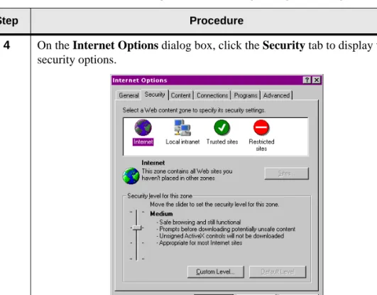
4 On the Internet Options dialog box, click the Security tab to display the security options.
Figure 1-2 Internet Options Dialog Box, Security Tab Table 1-2 Set Web Browser Settings for Internet Explorer (continued)
TransNav GUI Guide, Section 1: Installation and Overview
Configure Web Browser Settings for Internet Explorer
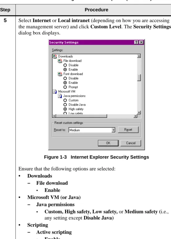
5 Select Internet or Local intranet (depending on how you are accessing the management server) and click Custom Level. The Security Settings dialog box displays.
Figure 1-3 Internet Explorer Security Settings Ensure that the following options are selected:
• Downloads – File download
• Enable
• Microsoft VM (or Java) – Java permissions
• Custom, High safety, Low safety, or Medium safety (i.e., any setting except Disable Java)
• Scripting
– Active scripting
• Enable
– Scripting of Java applets
• Enable Click OK.
Table 1-2 Set Web Browser Settings for Internet Explorer (continued)
Chapter 1 Installation for Windows Workstations
Configure Web Browser Settings for Internet Explorer
6 Restart your computer.
7 The Set Web Browser Settings for Internet Explorer procedure is complete.
Continue to the procedure Install GUI on a Windows Workstation, page 1-6.
Table 1-2 Set Web Browser Settings for Internet Explorer (continued)
TransNav GUI Guide, Section 1: Installation and Overview
Install the GUI Application on a Windows Workstation
Install the GUI Application on a Windows Workstation
Use this procedure to help you install the GUI application on a remote Windows workstation.
Table 1-3 Install GUI on a Windows Workstation
Step Procedure
1 Review the section Before You Install the GUI Application, page 1-1 before you start this procedure.
2 Verify that the management server is started. See Start the Server, page 2-25.
3 If this is the first time you are installing the application on this computer, complete the procedure Set Web Browser Settings for Internet Explorer, page 1-2.
4 Open your Web browser and connect to the server by entering the following address into the address window:
http://server:9090
where:
server is the name or IP address of the TransNav management server. The TransNav management system splash screen displays.
Chapter 1 Installation for Windows Workstations
Install the GUI Application on a Windows Workstation
5 Click the shelf icon to start the installation of the GUI application.
Figure 1-5 Shelf Icon on Splash Screen
6 The Installer Wizard displays.
Figure 1-6 Windows GUI Install Wizard
Follow the directions on the screen until the GUI application is installed on your computer.
7 The Install GUI on a Windows Workstation procedure is complete. Continue to the one of the procedures in Section 1—Installation and Overview, Chapter 3—“Starting the Graphical User Interface,” page 1-17. Table 1-3 Install GUI on a Windows Workstation (continued)
TransNav GUI Guide, Section 1: Installation and Overview
Uninstall the GUI from Windows Workstation
Uninstall the GUI from Windows Workstation
Before installing a new version of the GUI application, you must remove the old version. On a Windows 2000 Professional platform, the uninstallation process uses a wizard similar to the Install Wizard. After you have opened the Uninstaller Wizard, follow the directions on the screen to remove the GUI application from your computer. Table 1-4 Uninstall GUI from Windows Workstation
Step Procedure
1 From the Start menu, select Programs, then Turin Networks, and then Uninstall TransNav GUI.
2 The Uninstaller Wizard appears. Follow the directions on screen until the GUI application is removed from your computer.
Figure 1-7 Windows GUI Uninstall Wizard
3 In an Explorer window, navigate to the directory where the application was installed. Remove the remaining files.
4 The Uninstall GUI from Windows Workstation procedure is complete. If you are in the process of a node upgrade, return to Step 3 of the procedure Upgrade Server Software, page 2-38.
SECTION 1INSTALLATION AND OVERVIEW
Chapter 2
Installation for Solaris Workstations
Introduction You can manage a network of Traverse and TraverseEdge 100 nodes using either a Solaris or a Windows 2000 Professional platform. This chapter includes procedures on how to install the graphical user interface (GUI) on a Solaris platform.
• Before You Install the GUI Application, page 1-9
• Install the GUI Application on a Solaris Workstation, page 1-12
• Uninstall the GUI from a Solaris Workstation, page 1-15
See Chapter 1—“Installation for Windows Workstations,” page 1-1 for the procedures to install the GUI application on a Windows workstation.
Before You Install the GUI Application
To access the GUI on a computer other than the management server, install the GUI application onto the remote computer. Turin recommends installing the application directly onto the client workstation for faster initialization, operation, and response time.
Before you install the management server software, understand the following requirements.
Table 1-5 Before You Install the GUI application (Solaris)
Requirement Reference
GUI application requirements See the TransNav Management System Product Overview Guide, Section 2—Management System Planning,
Chapter 1—“TransNav Management System Requirements,” page 2-1
Solaris configuration requirements for GUI application.
If this is the first time you are installing the TransNav system on the workstation, use the following procedures to configure the environment:
• Configure Web Browser Settings for Netscape Navigator, page 1-10
• Configure Window Manager Settings for Solaris, page 1-11
Starting the GUI application See Section 1—Installation and Overview, Chapter 3—“Starting the Graphical User Interface,” page 1-17 for detailed procedures on starting the GUI application
TransNav GUI Guide, Section 1: Installation and Overview
Configure Web Browser Settings for Netscape Navigator
Configure Web Browser Settings for Netscape Navigator
Before installing the GUI application or launching the applet interface, your Web browser must have the correct settings for the application to work properly. Use this procedure to configure the browser settings for Netscape Navigator.
Table 1-6 Set Web Browser Settings for Netscape Navigator
Step Procedure
1 Open Netscape.
2 From the main menu, select Edit, then Preferences.
3 Click Advanced. The Preferences dialog box displays.
Figure 1-8 Netscape Navigator Preferences Dialog Box Ensure that the Enable Java, Enable JavaScript, and Enable style sheets check boxes are selected. Click OK.
4 The Set Web Browser Settings for Netscape Navigator procedure is complete.
Chapter 2 Installation for Solaris Workstations
Configure Window Manager Settings for Solaris
Configure Window Manager Settings for Solaris
If you are using the GUI application on a Sun Solaris workstation, the window manager settings must be properly configured to ensure that error dialog boxes pop up in front of all other windows.
From your Sun workstation, select Style Manager, and then select Window to display the Style Manager – Window dialog box:
Figure 1-9 Solaris Style Manager—Window Dialog Box
Clear the Raise Window When Made Active dialog box to ensure that error dialog boxes always pop to the front of the screen.
TransNav GUI Guide, Section 1: Installation and Overview
Install the GUI Application on a Solaris Workstation
Install the GUI Application on a Solaris Workstation
To access the management software on a computer other than the management server, you should install the GUI application onto the remote computer. Use this procedure to help you install the GUI application on a remote Solaris workstation.
Table 1-7 Install GUI on a Solaris Workstation
Step Procedure
1 Review the section Before You Install the GUI Application, page 1-9 before you start this procedure.
2 Verify that the management server is started. See Start the Server, page 2-25.
3 If this is the first time you are installing the application, complete the appropriate procedure:
• Configure Web Browser Settings for Netscape Navigator, page 1-10
• Configure Window Manager Settings for Solaris, page 1-11
4 Open a terminal window and change to the directory where you want to install the GUI application.
5 Open Netscape Navigator and connect to the management server by entering the following address into the address window:
http://server:9090
where:
serveris the name or IP address of the TransNav management server. The TransNav management system splash screen displays.
Chapter 2 Installation for Solaris Workstations
Install the GUI Application on a Solaris Workstation
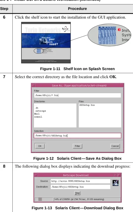
6 Click the shelf icon to start the installation of the GUI application.
Figure 1-11 Shelf Icon on Splash Screen
7 Select the correct directory as the file location and click OK.
Figure 1-12 Solaris Client—Save As Dialog Box
8 The following dialog box displays indicating the download progress:
Figure 1-13 Solaris Client—Download Dialog Box The dialog box closes when the download is complete.
9 From a terminal window, change to the directory where you installed the setup file.
Table 1-7 Install GUI on a Solaris Workstation (continued)
TransNav GUI Guide, Section 1: Installation and Overview
Install the GUI Application on a Solaris Workstation
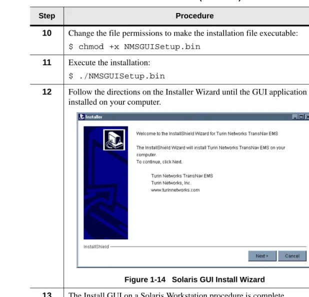
10 Change the file permissions to make the installation file executable:
$ chmod +x NMSGUISetup.bin
11 Execute the installation:
$ ./NMSGUISetup.bin
12 Follow the directions on the Installer Wizard until the GUI application is installed on your computer.
Figure 1-14 Solaris GUI Install Wizard
13 The Install GUI on a Solaris Workstation procedure is complete. Continue to the one of the procedures in Section 1—Installation and Overview, Chapter 3—“Starting the Graphical User Interface,” page 1-17. Table 1-7 Install GUI on a Solaris Workstation (continued)
Chapter 2 Installation for Solaris Workstations
Uninstall the GUI from a Solaris Workstation
Uninstall the GUI from a Solaris Workstation
Before installing a new version of the GUI application, you must remove the old version. On a Solaris platform, the uninstallation process uses a wizard similar to the Install Wizard. After you have opened the Uninstaller Wizard, follow the directions on screen to remove the GUI application from your computer.
Table 1-8 Uninstall GUI from Solaris Workstation
Step Procedure
1 From a terminal window, change directories to the directory above the directory above which the GUI was installed.
2 Remove the directory and contents:
rm -rf DirectoryName
where:
DirectoryNameis the name of the directory where you installed the
management system software.
3 The Uninstall GUI from Solaris Workstation procedure is complete. If you are in the process of a node upgrade, return to Step 3 of the procedure Upgrade Server Software, page 2-38.
TransNav GUI Guide, Section 1: Installation and Overview
SECTION 1INSTALLATION AND OVERVIEW
Chapter 3
Starting the Graphical User Interface
Introduction This chapter contains procedures on how to start the graphical user interface (GUI) for the TransNav management system.
• Starting the GUI from the Management Server, page 1-18
• Starting the GUI Application on a Windows Platform, page 1-19
• Starting the GUI Application on a Solaris Platform, page 1-21
• User Login, page 1-22
Turin recommends using the GUI application directly on the client workstation for faster initialization, operation, and response time.
• For Windows workstations, see Chapter 1—“Installation for Windows Workstations,” page 1-1.
• For Solaris workstations, see Chapter 2—“Installation for Solaris Workstations,” page 1-9.
TransNav GUI Guide, Section 1: Installation and Overview
Starting the GUI from the Management Server
Starting the GUI from the Management Server
If you are going to use the GUI on the same computer you are using as a management server, the user interface applications install at the same time you install the server software. Use this procedure to start the GUI on the same computer (Windows or Solaris) that the management server is running.
Table 1-9 Start the GUI Application from the Management Server
Step Procedure
1 Verify the management server is started. See the TransNav Management System Server Guide, Start the Server, page 2-25.
2 In the Server Admin application, click Execution, then click Start GUI.
Figure 1-15 Server Admin Application—Start GUI
3 The Login dialog box displays.
Figure 1-16 GUI Login Dialog Box
a. Enter the correct information in the following fields:
• User Name: Your user name assigned by the system administrator. Default is admin.
• Password: Your user password assigned by the system administrator. Default is admin.
• Host Name: Name of the management system host. If you are running the server and client on the same system, enter localhost.
b. Click Login.
4 The Start the GUI Application from the Management Server procedure is complete.
Chapter 3 Starting the Graphical User Interface
Starting the GUI Application on a Windows Platform
Starting the GUI
Application on a Windows Platform
To access the management software on a Windows workstation other than the management server, install the GUI application onto the remote computer (See Chapter 1—“Installation for Windows Workstations,” page 1-1). Use this procedure to start the GUI application on a remote computer.
Table 1-10 Start the GUI Application on a Windows Platform
Step Procedure
1 Verify the management server is started. See the TransNav Management System Server Guide, Start the Server, page 2-25.
2 Verify the GUI application is installed. See the procedure, Install GUI on a Windows Workstation, page 1-6.
3 From the Start menu, click Programs, Turin_Networks, then click TransNav(TM)
GUI.
TransNav GUI Guide, Section 1: Installation and Overview
Starting the GUI Application on a Windows Platform
4 The Login dialog box displays.
Figure 1-18 GUI Login Dialog Box
a. Enter the correct information in the following fields:
• User Name: Your user name assigned by the system administrator. Default is admin.
• Password: Your user password assigned by the system administrator. Default is admin.
• Host Name: Name of the management system host. If you are running the server and client on the same system, enter localhost.
b. Click Login.
5 The Start the GUI Application from the Management Server procedure is complete.
Continue to the procedure, Password Changes, page 2-3.
Table 1-10 Start the GUI Application on a Windows Platform (continued)
Chapter 3 Starting the Graphical User Interface
Starting the GUI Application on a Solaris Platform
Starting the GUI
Application on a Solaris Platform
To access the management software on a Solaris workstation other than the management server, install the GUI application onto the remote computer. (See Chapter 2—“Installation for Solaris Workstations,” page 1-9.)
Use this procedure to start the GUI application on a remote computer Table 1-11 Start the GUI Application on a Solaris Platform
Step Procedure
1 Verify the management server is started. See the TransNav Management System Server Guide, Start the Server, page 2-25.
2 Verify the GUI application is installed. See the procedure, Install GUI on a Solaris Workstation, page 1-12.
3 In a terminal window, change to the directory where you installed the GUI application.
4 Enter the following command:
$ ./ems_gui.sh
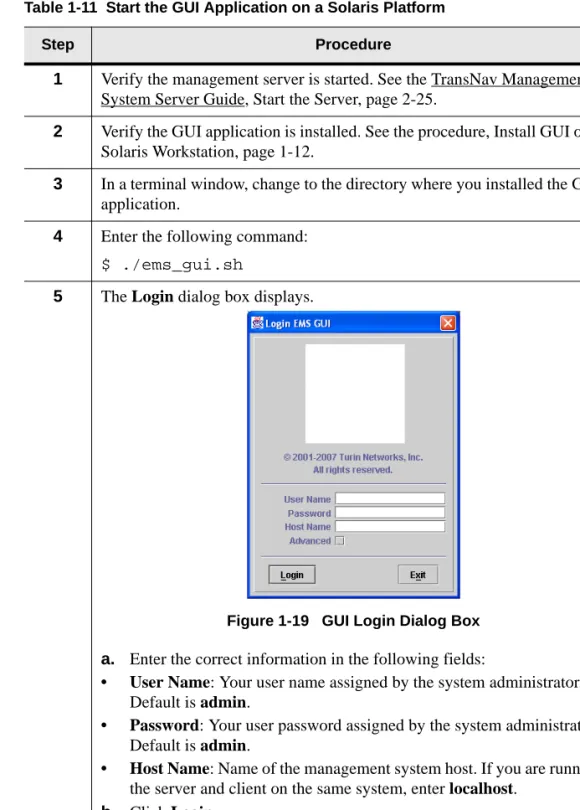
5 The Login dialog box displays.
Figure 1-19 GUI Login Dialog Box
a. Enter the correct information in the following fields:
• User Name: Your user name assigned by the system administrator. Default is admin.
• Password: Your user password assigned by the system administrator. Default is admin.
• Host Name: Name of the management system host. If you are running the server and client on the same system, enter localhost.
b. Click Login.
6 The Start the GUI Application from the Management Server procedure is complete.
TransNav GUI Guide, Section 1: Installation and Overview
User Login
User Login Turin recommends using the GUI application directly on the client workstation for faster initialization, operation, and response time.
When you start the GUI, the Login dialog box displays.
Figure 1-20 Login Dialog Box Enter the following information in the Login dialog box:
• User Name: Your user name assigned by the system administrator. Default is admin.
• Password: Your user password assigned by the system administrator. Default is admin.
• Host Name: Name of the management system host. If you are running the server and client on the same system, enter localhost.
Important: For security reasons, Turin recommends that you change the default User Name and/or Password. To create a new user account, see Domain Users, page 2-6 or Node User, page 2-13. To change the Password only, see Password Changes, page 2-3.
Chapter 3 Starting the Graphical User Interface
User Login
• Advanced: When this check box is selected, the advanced settings display.
Figure 1-21 Login Dialog Box - Advanced Settings
When the Advanced check box is selected, you can view and change the following parameters:
• Protocol: Select one of the following protocols:
– RMI (Remote Method Invocation)
– HTTP (Hyper Text Transfer Protocol)
– HTTPS (Hyper Text Transfer Protocol Secure)
• Port Number: Enter a port number.
• Notification: A notification is any change to the server database, such as new alarms or changes to configuration information. Select one of the following options:
– PUSH: The server automatically forwards notifications to the GUI.
– PULL: The GUI queries the server for new notifications every couple of seconds. Select this option if the client is located behind a firewall. Command buttons are as follows:
• Login: The User Name and Password combination is authenticated by the management system. Upon successful authentication, the system opens the main application window and closes the Login box. If authentication fails, you are denied access.
TransNav GUI Guide, Section 1: Installation and Overview
Chapter 3 Starting the Graphical User Interface
TransNav GUI Guide, Section 1: Installation and Overview
Chapter 3 Starting the Graphical User Interface
TransNav GUI Guide, Section 1: Installation and Overview
Chapter 3 Starting the Graphical User Interface
TransNav GUI Guide, Section 1: Installation and Overview
Chapter 3 Starting the Graphical User Interface
TransNav GUI Guide, Section 1: Installation and Overview
Chapter 3 Starting the Graphical User Interface
TransNav GUI Guide, Section 1: Installation and Overview
SECTION 1INSTALLATION AND OVERVIEW
Chapter 4
Graphical User Interface General Description
Introduction This chapter provides a description of the navigational components of the TransNav graphical user interface (GUI).
Using the GUI, you can view the network or domains you are managing (Map View) or any particular shelf (Shelf View). Context-sensitive tabs are available for the view selected.
The Map View (page 1-36) displays all the nodes in a network and is the initial display when you start the GUI.
The Traverse Shelf View (page 1-39) displays all the cards (modules) in a node and their associated ports.
The TE-100 Shelf View (page 1-42) displays the shelf view for the TE-100. This chapter also describes the following GUI features:
• GUI Menus, page 1-44
• GUI Conventions, page 1-51
• Resizing Capabilities, page 1-52
• Scroll Bars, page 1-51
TransNav GUI Guide, Section 1: Installation and Overview
Map View
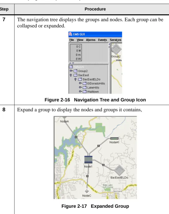
Map View Map View displays all of the node groups and discovered nodes for a server when you first start the GUI from that server. From Map View, you can see and manage all the nodes, node groups, links between the nodes, and network services. The graphic area displays a background image (usually a map of physical locations of the nodes) and icons representing the nodes. This initial background image is the Network Map view. Each node group can have a different background image associated with it; this is the Group Map.
Each user can group the nodes to which they have access in order to more easily manage their areas of responsibility. They can also add node groups within existing node groups. The node groups appear in the server network navigation tree.
Figure 1-22 Map View
The menu bar is context-sensitive. Commands display as available (highlighted) or unavailable (grayed out), depending on the selected object. The server network alarm summary tree gives you visibility at a glance to network alarms. If you select a node group, only alarms associated with that node group display.
The network navigation tree shows you the node groups and node networks attached to the server in an outline format in alphanumeric order. Node groups display first, then nodes. In Map View, clicking a node group or a node displays the node group or node name on the top and bottom bars of the window. To view the nodes in a node group, double-click the Group icon in Map View or expand the node group in the navigation tree. In Shelf View, right-clicking a node in the navigation tree or double-clicking the node in Map View to display a graphical representation of the node and related information; you can see which object (card or port) you have selected by the white rectangle around the object and the name that displays on the top and bottom bars of the window.
The context-sensitive tabs provide server, node group, or node information on alarms, events, configuration information, protection, services, and service groups.
Menu bar Currently selected object Context-sensitive tabs Alarm summary tree Network navigation tree
Chapter 4 Graphical User Interface General Description
Shortcut Menus for Map View
Double-click a node group to display the node groups and nodes associated with it. Click a node to display node-specific information. Click anywhere on the map to display network information specific to the server.
The tabs allow you to view and change the following information:
• Alarms: Alarms on nodes in the domain. See Section 8—Maintenance and Testing, Chapter 2—“Alarms.”
• Events: Events on nodes in the domain. See Section 8—Maintenance and Testing, Chapter 3—“Events.”
• Config: Configuration information for the selected piece of equipment. See Section 5—Equipment Configuration.
• Protection: Define protected rings. See Section 4—Protection Switching • Performance: Monitor performance and VT/TU capacity data. See
Section 8—Maintenance and Testing, Chapter 1—“Performance Monitoring.”
• Service: Define services between nodes in a domain. See Section 6—Services.
Shortcut Menus for Map View
Two shortcut menus are available in Map View:
• Right-click a node
• Right-click the background image
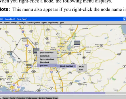
When you right-click a node, the following menu displays.
Note: This menu also appears if you right-click the node name in the navigation tree.
Figure 1-23 Map View Shortcut Menu #1 Menu selections are:
• Show Shelf View: View the selected shelf (node).
• Delete Node: Delete the selected node (shelf).
• Synchronize Node: Synchronize the node with the management server so the server contains the most recent node configuration and alarms information.
TransNav GUI Guide, Section 1: Installation and Overview
Shortcut Menus for Map View
• Alarm Audit: Clears alarms on the node that do not exist and raises alarms that are present but not shown at the management layer.
• Sub Shelf:Select to access the Attach Sub Shelf menu selection, then choose to attach a TA200 or a TE50 sub shelf.
When you right-click the background image, the following menu displays:
Figure 1-24 Map View Shortcut Menu #2 Menu selections are:
• Show Network Map: Show the background map selected for the network. This option appears if node groups within the network have different background maps.
• Add Node: Add a node. For details, see Section 3—Network,
Chapter 1—“Creating and Deleting Equipment Using Preprovisioning,” Add a Node.
• Add Link: Add a physical link between ports. See Section 3—Network, Chapter 1—“Creating and Deleting Equipment Using Preprovisioning,” Add a Link, page 3-15.
• Add Group: Create a new group of nodes or add a node to a group.
• Change Background: Select to change the background map.
• Zoom In: Zoom in on the current view.
• Zoom Out: Zoom out on the current view.
Chapter 4 Graphical User Interface General Description
Traverse Shelf View
Traverse Shelf View
Shelf View displays all of the cards in a node and their associated ports. You can navigate to Shelf View in the following ways:
• Click the node in Map View, then select Show Shelf View from the View menu.
• Double-click the node in Map View.
• Right-click a node in Map View and select Show Shelf View.
• Right-click a node name in the Navigation Tree and select Show Shelf View.
Figure 1-25 Shelf View
The menu bar is context-sensitive. Commands are displayed as available (highlighted) or unavailable (grayed out), depending on the selected object.
You can see which object you have selected by the white rectangle around the object in the graphic and the name displayed on the top and bottom bars of the window.
Context-sensitive tabs (in the bottom half of the screen) provide information on alarms, events, configuration information, protection, and services. In Shelf View, these tabs provide single node, card, or port information. Click a card to display card-specific information. Click a port to display port-specific information. Click an external clock to display external clock timing information.
Context-sensitive tabs allow you to view and change the following information:
• Alarms: Alarms on the selected card or port. See Section 8—Maintenance and Testing, Chapter 2—“Alarms,” page 8-11.
Currently selected object Menu bar BITS clock Context-sensitive tab screen Alarm indicators
TransNav GUI Guide, Section 1: Installation and Overview
Shortcut Menu for Shelf View
• Events: Events on the selected card or port. See Section 8—Maintenance and Testing, Chapter 3—“Events,” page 8-25.
• Config: Configuration information on the selected card or port. See Section 5—Equipment, page 5-1.
• Diagnostic: Diagnostics tests on the selected port. See Section 8—Maintenance and Testing, Chapter 4—“Diagnostics,” page 8-37.
• Timing: Timing information on the selected card or port. See Section 3—Network, Chapter 3—“Node Timing,” page 3-21.
• DCC Tunnel: Configure DCC tunnels on the node. See Section 3—Network, Chapter 4—“DCC Tunnels,” page 3-33.
• Protection: Protection groups for the node. See Section 4—Protection Switching, page 4-1.
• Performance: Performance monitoring data for the selected card or port and capacity monitoring data for selected VT/TU cards. See Section 8—Maintenance and Testing, Chapter 1—“Performance Monitoring,” page 8-1.
• Ethernet: Configure EOS, LAG, and Policer on the node. See Section 5—Equipment, Chapter 4—“Ethernet Equipment,” page 5-49.
• Test Access: Provides non-intrusive monitoring and intrusive split testing on digital cross-connect and add-drop multiplexer systems. See
Section 8—Maintenance and Testing, Chapter 5—“Test Access.”
• Service: Services provided from the node. See Section 6—Services.
You can see which object you have selected by the white rectangle around the object and the name displayed on the top and bottom bars of the window.
Shortcut Menu for Shelf View
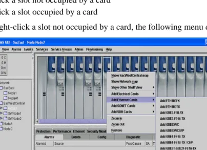
Two shortcut menus are available in Shelf View.
• Right-click a slot not occupied by a card
• Right-click a slot occupied by a card
When you right-click a slot not occupied by a card, the following menu displays:
Chapter 4 Graphical User Interface General Description
Shortcut Menu for Shelf View
Menu selections are:
• Show (Node Group) map: Show the node group (i.e., parent) map if this node is part of a node group.
• Show Network map: Show the map for the entire domain.
• Show Other Shelf View: Select another node to view in Shelf View.
• Add [card type] Card: Add a card to the shelf in the selected slot.
• Zoom In: Zoom in on the current view.
• Zoom Out: Zoom out on the current view.
• Restore: Restore the original view.
When you right-click a slot occupied by a card, a different menu displays.
Figure 1-27 Shelf View Shortcut Menu #2 Menu selections are:
• Show (Node Group) map: Show the node group (i.e., parent) map if this node is part of a node group.
• Show Network map: Show the map for the entire domain.
• Show Other Shelf View: Select another node to view in Shelf View.
• Delete Card: Delete the selected card.
• Restart Card Warm: Restart the processor on the selected card (hitless).
• Restart Card Cold: Restart the selected card.
• Replace with [card type] Cards: Replace the card selected in Shelf View with the card type selected on the shortcut menu.
• Zoom In: Zoom in on the current view.
• Zoom Out: Zoom out on the current view.
TransNav GUI Guide, Section 1: Installation and Overview
TE-100 Shelf View
TE-100 Shelf View
When you double-click a node, you see the Shelf View which includes a network alarm summary and navigation tree on the left, a graphical version of the shelf at the top right, and context-sensitive tab screens at the bottom right.
Figure 1-28 TraverseEdge 100 Shelf View
See the TraverseEdge 100 User Guide for detailed information about installing and commissioning the TE-100.
Alarm summary tree Network navigation tree Context-sensitive tab screen
Optical Ports 1 and 2 (click for port configuration)
and SFP Ports (click for SFP information) External
Synchronization References A and B
Tributary Card Ports (6 FE, 2 GbE, 3
Chapter 4 Graphical User Interface General Description
Shortcut Menu for Shelf View
Shortcut Menu for Shelf View
Two shortcut menus are available in Shelf View:
• Right-click a slot not occupied by a card
• Right-click a slot occupied by a card
When you right-click a slot not occupied by a card, the following menu displays:
Figure 1-29 Shelf View Shortcut Menu #1 Menu selections are:
• Show (Node Group) map: Show the node group (i.e., parent) map if this node is part of a node group.
• Show Network map: Show the map for the entire domain.
• Show Other Shelf View: Select another node to view in Shelf View.
• Add [card type] Cards: Add a card to the shelf in the selected slot with the card type selected on the shortcut menu.
• Zoom In: Zoom in on the current view.
• Zoom Out: Zoom out on the current view.
TransNav GUI Guide, Section 1: Installation and Overview
GUI Menus
When you right-click a slot occupied by a card, a different menu displays.
Figure 1-30 Shelf View Shortcut Menu #2 Menu selections are:
• Show (Node Group) map: Show the node group (i.e., parent) map if this node is part of a node group.
• Show Network map: Show the map for the entire domain.
• Show Other Shelf View: Select another node to view in Shelf View.
• Delete Card: Delete the selected card.
• Restart Card Warm: Restart the processor on the selected card (hitless).
• Restart Card Cold: Restart the selected card.
• Replace with [card type] Card: Replace the card selected in Shelf View with the card type selected on the shortcut menu.
• Zoom In: Zoom in on the current view.
• Zoom Out: Zoom out on the current view.
• Restore: Restore the original view.
GUI Menus Each menu in the menu bar is context-sensitive. Items can be displayed as available (highlighted) or unavailable (grayed out) depending on the currently active object. The following sections summarize the available menu options:
• File Menu, page 1-45
• View Menu, page 1-45
• Alarm Menu, page 1-46
• Events Menu, page 1-46
• Services Menu, page 1-47
• Service Groups Menu, page 1-48
Chapter 4 Graphical User Interface General Description
View Menu
• Provisioning Menu, page 1-51
• Help Menu, page 1-51
File Menu Use the commands on the File menu to manage user preferences. See
Section 2—Administrative Tasks, Chapter 3—“User Preferences,” page 2-15 for detailed information about these commands.
View Menu Use the commands on the View menu to set your screen to your required dimensions. Figure 1-31 File Menu
1. Import User Preferences. Import Alarms and Events sorting and filter settings saved under the user name.
2. Save User Preferences. Save Alarms and Events sorting and filter settings and Map View background image under the current user name.
3. Exit. Exit the application and close the main window.
1. 2. 3.
Figure 1-32 View Menu
1. Show Parent Map: Display the map of the nodes and links one level above the present Map View.
2. Show Network Map: Display the map of nodes and links within the domain.
3. Show Shelf View: Display the Shelf View of a selected node.
4. Zoom In - CTRL-I: Zoom in on the current view.
5. Zoom Out - CTRL-O: Zoom out on the current view.
6. Restore - CTRL-C: Restore the view to the default setting.
1. 2. 3. 4. 5. 6.
TransNav GUI Guide, Section 1: Installation and Overview
Alarm Menu
Alarm Menu Use the commands on the Alarm menu to help you manage information on the Alarms tab. See Section 8—Maintenance and Testing, Chapter 2—“Alarms,” page 8-11 for detailed information about the Alarm tab.
Events Menu Use commands on the Events menu to help you manage the information on the Events tab. See Section 8—Maintenance and Testing, Chapter 3—“Events,” page 8-25 for detailed information about the Events tab.
Figure 1-33 Alarm Menu
1. Set Filters: Open the Alarm Filter (View Main) dialog box. Allows you to filter displayed alarms by source, probable cause, time, or severity.
2. New Window: Open an independent Alarm View dialog box that inherits the alarm filters set for the Alarms tab.
3. Acknowledge: Acknowledge the selected alarm.
4. Detail View: Display selected alarm details through the Alert Detail (View Main) dialog box.
1. 2. 3. 4.
Figure 1-34 Events Menu
1. Set Filters: Open the Event Filter (View Main) dialog box. Allows you to filter displayed events by source, probable cause, time, or severity.
2. New Window: Open an independent Event View dialog box that inherits the event filters set for the Events tab.
3. Settings: Open the Event Retrieval Settings (View Main) dialog box and change how often events are retrieved and refreshed.
4. Refresh: Display events that have occurred since the last time Refresh was clicked.
5. Detail View: Display selected event details through the Event Detail (View Main) dialog box.
1. 2. 3. 4. 5.
Chapter 4 Graphical User Interface General Description
Services Menu
Services Menu Use the commands on the Services menu to help you manage information on the Service tab. See Section 6—Services for detailed information on services.
Figure 1-35 Services Menu
1. Show TxRx Path: Display the active and standby paths for a selected service in the forward and reverse directions.
2. Show RSTP Port Info: Shows the RSTP port information for TLS services.
3. Show Last Error: Display the last error for the selected service.
4. Abort: Abort in-progress service activation, deactivation, or deletion.
5. Activate: Activate the selected service.
6. Deactivate: Deactivate the selected service.
7. Roll: Transfer traffic from one facility to another without interrupting service. Create all the bridge services individually first, then roll and commit multiple services. See the Traverse Provisioning Guide, Section 5—Creating Service Applications, Chapter 2—“Bridging and Rolling Services,” page 5-13 for detailed procedures on bridging and rolling services.
8. Unroll: An undo command.
9. Commit Rolled: After you roll traffic to a new facility, commit the transfer and delete the original service.
10.Edit: Edit a selected service.
11.Delete: Delete a selected service.
12.Duplicate: Duplicate the selected service.
1. 2. 3. 4. 5. 6. 7. 8. 9. 10. 11. 12.
TransNav GUI Guide, Section 1: Installation and Overview
Service Groups Menu
Service Groups Menu
Use commands on the Service Groups menu to help you manage information on the Service Group tab. See Section 6—Services, Chapter 6—“Service Groups” for detailed information about the Service Group tab.
Admin Menu Use the commands on the Admin menu to perform administrative functions in the network. The following descriptions for each command lists the appropriate cross-references to specific topics in the documentation for detailed information. Figure 1-36 Services
Groups Menu
1. Synchronize: Synchronize services created on the server with the nodes in the network.
2. Activate: Activate the selected service group.
3. Deactivate: Deactivate the selected service group.
4. Edit: Edit the selected service group.
5. Delete: Delete the selected service group.
1. 2. 3. 4. 5.
Figure 1-37 Admin Menu
1. Performance Templates: Define performance monitoring and capacity monitoring (VT/TU only) templates.
See Section 8—Maintenance and Testing, Chapter 1—“Performance Monitoring,” page 8-1.
2. Bandwidth Profiles: Create Ethernet bandwidth profiles on the TransNav management server.
3. Classifiers: Create Ethernet traffic management classifiers for the Traverse on the TransNav management server.
4. TE100Classifiers: Create Ethernet traffic management classifiers for the TE-100 on the TransNav management server.
5. Alarm Profiles: Set alarm profiles, including severities, for
non-service-affecting and service-affecting alarms; also for disabling and enabling alarms. See Section 8—Maintenance and Testing, Chapter 2—“Alarms,” page 8-11.
6. Reports: Generate and define reports. See Section 2—Administrative Tasks, Chapter 4—“Administrative Tasks,” page 2-25.
7. Customer: Define customer information. See
Section 2—Administrative Tasks, Chapter 4—“Administrative Tasks,” page 2-25. 1. 2. 3. 4. 5. 6. 7. 9. 11. 12. 8. 10. 13. 14. 15. 16. 17. 18. 19. 20. 21. 22.
Chapter 4 Graphical User Interface General Description
Admin Menu
8. Functional Groups: Define, change, or delete functional groups for domain user security using pre-defined roles and node access. See Section 2—Administrative Tasks, Chapter 1—“Managing Server Security,” page 2-1.
9. Domain User: Define, change, or delete a domain user through pre-defined roles. See Section 2—Administrative Tasks, Chapter 1—“Managing Server Security,” page 2-1.
10.Node User: Define, change, or delete a node user through pre-defined access groups. See Section 2—Administrative Tasks, Chapter 2—“Managing Node Security,” page 2-11.
11.Current User: Display the current user name and change the password. See Section 2—Administrative Tasks,
Chapter 1—“Managing Server Security,” page 2-1.
12.Session List: Display the current users on the management system.
13.Discovery: Enter the name or IP address of the Management Gateway Node(s). See Section 3—Network, Chapter 2—“Network Auto Discovery,” page 3-19.
14.SW Upgrade: Perform a software upgrade. See
Section 8—Maintenance and Testing, Chapter 6—“Software Upgrades,” page 8-47.
15.SW Activation: Activate the software.
16.IP Static Route Configuration: Add static routes to a node for management IP traffic.
17.OSI Static Route Configuration: Add static routes to a node for OSI (open system interconnection). (Planned for future release.)
18.OSI Parameters Configura