4655 Great America Parkway Santa Clara, CA 95054
*217315-A Rev 00*
Firewall User’s Guide and
Command Reference
Service Delivery Module 8660 Release 2.2.7 for the
Passport 8600 Series Switch
Copyright © Nortel Networks Limited 2005. All rights reserved.
This document is protected by copyright and distributed under licenses restricting its use, copying, distribution, and decompilation. No part of this document may be reproduced in any form by any means without prior written authorization of Nortel Networks, Inc. Documentation is provided “as is” without warranty of any kind, either express or implied, including any kind of implied or express warranty of non-infringement or the implied warranties of merchantability or fitness for a particular purpose.U.S. Government End Users: This document is provided with a “commercial item” as defined by FAR 2.101 (Oct 1995) and contains “commercial technical data” and “commercial software documentation” as those terms are used in FAR 12.211-12.212 (Oct 1995). Government End Users are authorized to use this documentation only in accordance with those rights and restrictions set forth herein, consistent with FAR 12.211- 12.212 (Oct 1995), DFARS 227.7202 (JUN 1995) and DFARS 252.227-7015 (Nov 1995). Nortel Networks, Inc. reserves the right to change any products described herein at any time, and without notice. Nortel Networks, Inc. assumes no responsibility or liability arising from the use of products described herein, except as expressly agreed to in writing by Nortel Networks, Inc. The use and purchase of this product does not convey a license under any patent rights, trademark rights, or any other intellectual property rights of Nortel Networks, Inc.
Service Delivery Module 8660 Release 2.2.7 for the Passport 8600 Series Switch, Alteon 5008, 5010, 5012, 5100, 5300, 5400, 5500, 5600, 5700, 5105, 5106, 5109, 5114, 5308, 5408, 5610, 5710, Alteon iSD-SFD, Alteon Firewall, Firewall OS, Alteon SFA, Alteon Firewall Accelerator, and Alteon Accelerator OS are trademarks of Nortel Networks, Inc. in the United States and certain other countries.
Check Point, OPSEC, and SmartUpdate are trademarks of Check Point Software Technologies Ltd. FireWall-1 and VPN-1 are registered trademarks of Check Point Software Technologies Ltd. Portions of this manual are Copyright © 2001 Check Point Software Technologies Ltd. All Rights Reserved.
Portions of this manual are Copyright © 2001 Dell Computer Corporation. All Rights Reserved. Any other trademarks appearing in this manual are owned by their respective companies.
Export
This product, software and related technology is subject to U.S. export control and may be subject to export or import regulations in other countries. Purchaser must strictly comply with all such laws and regulations. A license to export or reexport may be required by the U.S. Department of Commerce.
Licensing
This product includes software developed by Check Point Software Technologies
(http://www.checkpoint.com). This product also contains software developed by other parties. See Appendix C, “Software licenses,” for more information.
Regulatory Compliance
FCC Class A Notice. The equipment complies with Part 15 of the FCC Rules. Operation is subject to the following two conditions: 1) The device may not cause harmful interference, and 2) This equipment must accept any interference received, including interference that may cause undesired operation.
The equipment has been tested and found to comply with the limits for a Class A digital device, pursuant to Part 15 of the FCC Rules. These limits are designed to provide reasonable protection against harmful interference in a residential installation. The equipment generates, uses and can radiate radio-frequency energy and, if not installed and used in accordance with the instructions, may cause harmful interference to radio communications. However, there is no guarantee that interference will not occur in a particular installation. Operation of this equipment in a residential area is likely to cause harmful interference. In such a case, the user will be required to correct the interference at his own experience.
Do not make mechanical or electrical modifications to the equipment.
Industry Canada: This Class A digital apparatus meets all requirements of the Canadian Interference-Causing Equipment Regulations.
Cet appareil Numérique de la classe A respecte toutes les exigences du Règlements sur le matériel brouilleur du Canada.
VCCI Class A Notice: This is a Class A product based on the standard of the Voluntary Control Council for Interference from Information Technology Equipment (VCCI). If this equipment is used in a domestic environment, radio disturbance may occur. In such a case, the user may be required to take corrective actions.
Japanese VCCI Class A Notice
Taiwan EMC Notice
CE Notice: The CE mark on this equipment indicates that this equipment meets or exceeds the following technical standards: EN55022, EN55024, EN60950, and all supporting document requirements.
Safety Information
Caution—Nortel Networks products are designed to work with single-phase power systems having a grounded neutral conductor. To reduce the risk of electric shock, do not plug Nortel Networks products into any other type of power system. Contact your facilities manager or a qualified electrician if you are not sure what type of power is supplied to your building.
Caution—Not all power cords have the same ratings. Household extension cords do not have overload protection and are not meant for use with computer systems. Do not use household extension cords with your Nortel Networks product.
Caution—Your Nortel Networks product is shipped with a grounding type (three-wire) power cord. To reduce the risk of electric shock, always plug the cord into a grounded power outlet.
Nordic Lithium Battery Cautions
(Norge) ADVARSEL—Litiumbatteri - Eksplosjonsfare. Ved utskifting benyttes kun batteri som anbefalt av apparatfabrikanten. Brukt batteri returneres apparatleverandøren.
(Sverige) VARNING—Explosionsfara vid felaktigt batteribyte. Använd samma batterityp eller en ekvivalent typ som rekommenderas av apparattillverkaren. Kassera använt batteri enligt fabrikantens instruktion.
(Danmark) ADVARSEL! Litiumbatteri - Eksplosionsfare ved fejlagtig håndtering. Udskiftning må kun ske med batteri af samme fabrikat og type. Levér det brugte batteri tilbage til leverandøren.
(Suomi)VAROITUS—Paristo voi räjähtää, jos se on virheellisesti asennettu. Vaihda paristo ainoastaan laitevalmistajan suosittelemaan tyyppiin. Hävitä käytetty paristo valmistajan ohjeiden mukaisesti.
Warranty
Nortel Networks provides a limited warranty on all its products for a period of one year from the date of shipment. Free technical support and free replacement of hardware is provided for the first 90 days after shipment. You may choose to purchase additional service and support from Nortel Networks. Please contact your local sales representative for more information.
Preface . . . 15
Who Should Use This Book . . . .15
How This Book Is Organized . . . .15
Typographic Conventions . . . .17
Locating your software . . . .18
Reading path . . . .19
How to Get Help . . . .20
Chapter 1
Introduction . . . 21
Feature summary . . . .21
Software . . . .21
Hardware . . . .22
Firewall iSD ports . . . .23
Performance . . . .25
Certification . . . .25
System management . . . .25
Logging and monitoring . . . .25
8660 SDM basics . . . .26
Network elements . . . .26
Networks . . . .26
Firewalls . . . .27
Management interfaces . . . .27
Passport 8600 and firewall iSD VLANs . . . .28
Chapter 2
Initial setup . . . 31
Basic requirements . . . 32
Example networks . . . 33
Network elements . . . 35
Firewall iSD management network . . . 35
SmartCenter Server . . . 35
Trusted network . . . 36
Untrusted network (Internet) . . . 36
Using the CLI for basic configuration . . . 36
New Passport 8600 CLI commands for the 8660 SDM . . . 36
config naap . . . 37
show naap . . . 37
config cluster . . . 38
show cluster . . . 38
Modified Passport 8600 CLI commands for the 8660 SDM . . . 39
config vlan <vid> create . . . 39
show config module <value> . . . 40
Configuring the 8660 SDM . . . 41
Initializing the firewall iSD . . . 44
Using the join command . . . 50
Creating the firewall interface . . . 52
Configuring VRRP . . . 53
Configuring the firewall iSD and Check Point SmartCenter Server static routes . . 54
Setting the license key . . . 54
Example: . . . 54
Switching management and console ports among iSDs . . . 56
Switching iSDs . . . 56
Halting disk drives on the 8660 SDM . . . 57
Halting configured firewall iSDs . . . 57
Halting non-configured firewall iSDs . . . 59
Reinitializing halted firewall iSDs . . . 61
Allowing SMART Client access to the iSDs . . . 62
Installing Check Point management tools . . . 62
Editing the Windows NT hosts file . . . 63
Installing Check Point SmartServer and SmartConsole . . . 64
Defining a firewall object in the SmartDashboard . . . 76
Managing all clusters from one Check Point management station . . . .82
Creating a firewall policy test rule . . . .86
Creating and installing firewall iSD security rules . . . .89
Managing Check Point licenses . . . .90
Installing central licenses with SmartUpdate . . . .90
Re-installing an existing license . . . .91
Installing a license on an NT Workstation . . . .92
Chapter 3
Using JDM to configure firewall iSDs . . . 93
Overview of JDM tasks . . . .93
Configuring firewall iSD clusters . . . .93
Creating firewall VLANs . . . .97
Configuring VLAN IP addresses . . . .102
Enabling and disabling NAAP . . . .104
Enabling and disabling a firewall iSD . . . .105
Viewing firewall iSD states . . . .107
Accessing the Browser-Based Interface . . . .109
Viewing SDM Management Port properties . . . .110
Example network configuration . . . .111
Chapter 4
System management basics. . . 119
Management tools . . . .119
Users and passwords . . . .120
Chapter 5
The Command Line Interface . . . 123
Accessing the CLI . . . .123
Using the local serial port . . . .123
Defining the remote access list . . . .124
Displaying the access list . . . .124
Adding items to the access list . . . .124
Using Telnet . . . .125
Using Secure Shell . . . 127
Enabling SSH access on the firewall iSD . . . 127
Starting the SSH session . . . 129
Using the CLI . . . 129
Basic operation . . . 129
The Main Menu . . . 130
Idle time-out . . . 131
Multiple administration sessions . . . 131
Global commands . . . 131
Command line history and editing . . . 133
Command line shortcuts . . . 134
Command stacking . . . 134 Command abbreviation . . . 134 Tab completion . . . 134
Chapter 6
Command reference . . . 135
Main Menu 135 Information Menu 138 Info_host Menu 140 Information Menu 141Route Information Menu 141 VRRP Information Menu 143 Configuration Menu 144
System Menu 146 Backup Menu 148 Date and Time Menu 149 DNS Servers Menu 151 Cluster Menu 152 Access List Menu 154
Administrative Applications Menu 155 Platform Logging Menu 173
User Menu 178
Network Configuration Menu 183 Port Menu 184
Interface Menu 185 VRRP Interface Menu 187
VRRP Settings Menu 188 Advanced Settings Menu 191 Firewall License Menu 204 Firewall Configuration Menu 205
Sync Configuration Menu 207 SMART Clients Menu 208
SmartUpdate Configuration Menu 208 Miscellaneous Settings Menu 209
Boot Menu 210
Software Management Menu 211 The Maintenance Menu 212
Diagnostic Tools Menu 213
Firewall Maintenance Menu 213 Tech Support Dump Menu 214 OSPF Debug Menu 215
Chapter 7
Browser-Based Interface. . . 217
Features . . . .217
Getting started . . . .218
Requirements . . . .218
Enabling the Browser-Based Interface . . . .218
Setting up the web browser . . . .220
Starting the Browser-Based Interface . . . .220
Browser-Based Interface basics . . . .222
Interface components . . . .222
Basic operation . . . .223
Global command forms . . . .224
Apply . . . .225 Diff . . . .227 Revert . . . .228 Logout . . . .229 Help . . . .230
Chapter 8
BBI forms reference. . . 233
Monitor forms . . . 234 Monitor > System . . . 234 Monitor > Hosts . . . 235 Monitor > Syslog . . . 236 Monitor > About . . . 237 Cluster forms . . . 238 Cluster > Time . . . 238 Cluster > iSDs . . . 239
Cluster > Logs > Syslog . . . 240
Cluster > Logs > ELA . . . 241
Cluster > Logs > Archive . . . 243
Cluster > Miscellaneous . . . 244
Network forms . . . 245
Network > DNS . . . 246
Network > NTP . . . 247
Network > Ports . . . 248
Network > Ports > Update (Add or Modify) . . . 249
Network > Interfaces . . . 250
Network > Interfaces > Update (Add or Modify) . . . 251
Network > VRRP . . . 252
Network > Gateway . . . 254
Network > Routes > Static . . . 254
Network > Routes > Static > Update (Add, Delete, or Modify) . . . 255
Network > Routes > Proxy ARP . . . 256
Network > Routes > OSPF > General . . . 257
Network > Routes > OSPF > Area Index . . . 258
Network > Routes > OSPF > Area Index > Update (Add or Modify) . . . 259
Network > Routes > OSPF > Interface . . . 260
Network > Routes > OSPF > Interface > Update (Modify) . . . 261
Firewall forms . . . 263
Firewall > Settings . . . 263
Firewall > License Management . . . 264
Firewall > License Management > Update (Delete or Modify) . . . 265
Firewall > Synchronization . . . 267
Operations forms . . . 268
Operation > Update . . . .269
Administration forms . . . .271
Administration > Users . . . .272
Administration > Users > Add New User . . . .273
Administration > Access List . . . .274
Administration > Access List > Update (Add or Modify) . . . .275
Administration > Telnet-SSH . . . .276
Administration > Web > General . . . .277
Administration > Web > Create Cert . . . .278
Administration > Web > Server Certs . . . .279
Administration > Web > Server Certs > Update (Add or Modify) . . . .280
Administration > Web > CA Certs . . . .281
Administration > Web > CA Certs > Update (Add or Modify) . . . .282
Administration > SNMP > General . . . .283
Administration > SNMP > System . . . .284
Administration > SNMP > Trap Hosts . . . .285
Administration > SNMP > Trap Hosts > Update (Add or Modify) . . . .286
Administration > SNMP > USM Users . . . .287
Administration > SNMP > USM Users > Update (Add or Modify) . . . .288
Administration > SNMP > Advanced . . . .289
Diagnostics forms . . . .290
Diagnostics > System Commands . . . .290
Chapter 9
Applications . . . 293
Virtual Router Redundancy Protocol . . . .294
VRRP on the firewall iSDs . . . .294
Firewall iSD cluster and VRRP . . . .294
VRRP router parameters . . . .295
Active master determination . . . .296
High Availability firewall configuration . . . .299
Requirements . . . .300
Installing the redundant firewall iSD . . . .301
Configuring the redundant firewall iSD . . . .301
Synchronizing firewall iSDs . . . 309
Configuring synchronization using the CLI . . . 309
Configure HA at the Check Point SmartDashboard . . . 310
Example SmartDashboard configuration for HA . . . 312
Chapter 10
Open Shortest Path First. . . 317
OSPF overview . . . 317
Types of OSPF areas . . . 318
Types of OSPF routing devices . . . 319
Neighbors and adjacencies . . . 319
Link-State Database . . . 320
Shortest Path First tree . . . 320
Authentication . . . 321
Internal and external routing . . . 321
Firewall OSPF implementation . . . 322
Configurable parameters . . . 322
Defining areas . . . 323
Assigning the area index . . . 323
Using the area ID to assign the OSPF area number . . . 324
Attaching an area to a network . . . 324
Interface cost . . . 325
Electing the DR and BDR . . . 325
Router ID . . . 326
Authentication . . . 326
Simple authentication . . . 326
MD5 authentication . . . 326
OSPF features not supported in this release . . . 327
OSPF configuration examples . . . 327
Example 1: simple OSPF domain . . . 328
Configuring a single firewall iSD with OSPF . . . 328
Configuring OSPF support . . . 330
Chapter 11
Upgrading the software. . . 333
Compatibility . . . .334
Types of upgrade . . . .335
Firewall iSD upgrades . . . .335
Built-in firewall software upgrades . . . .336
Check Point management station upgrades . . . .336
Overview of upgrade tasks . . . .336
Installing a minor/major release upgrade . . . .337
Activating the software upgrade package . . . .339
Single member (iSD) cluster upgrade . . . .339
Two member (iSD) cluster upgrade . . . .340
Reinstalling Software . . . .345
Reinstalling software using FTP . . . .345
Chapter 12
Event Logging API . . . 349
Configure the Check Point SmartCenter Server . . . .350
Configuring ELA on the firewall iSD . . . .355
The Check Point SmartView Tracker . . . .357
Appendix A
Common tasks . . . 359
Tuning Check Point NG performance . . . .360
Connection parameters . . . .360
NAT parameters . . . .361
Reading system memory information . . . .362
Cluster backup and clone procedures . . . .363
Backing up . . . .363
Cloning . . . .364
Generating a public or private DSA key pair . . . .366
Appendix B
Troubleshooting . . . 369
Actions . . . 369
Cannot download policy on firewall iSD . . . 371
Action . . . 371
Poor performance with other devices . . . 371
Action . . . 371
Cannot log into the management station from the SMART Client . . . 372
Actions . . . 372
Check Point sends connection failed messages to the firewall iSD . . . 372
Action . . . 372
VRRP configuration tips . . . 372
VRRP: active master backup fails . . . 374
Actions . . . 374
VRRP: Both masters are active . . . 375
Actions . . . 375
Poor performance under heavy traffic . . . 376
Action . . . 376
Appendix C
Software licenses. . . 377
Apache Software Licence . . . 377
mod_ssl License . . . 378
OpenSSL and SSLeay Licenses . . . 379
OpenSSL License . . . 379
Original SSLeay License . . . 380
PHP License . . . 381
SMTPclient License . . . 382
GNU General Public License . . . 383
This User’s Guide describes the components and features of the 8660 Service Delivery Module Firewall 1 (SDM FW1), FW2, and FW4 system and explains how to perform initial setup, configuration, and maintenance.
The term “8660 SDM” is used in this document when descriptions or procedures apply to any of the 8660 SDM models (SDM FW1, FW2, and FW4). When references are to specific 8660 SDM boards, the model is referenced.
The firewall modules consist of a processor PCI Mezzanine Card (PrPMC) and a disk drive. The PrPMC and disk drive are referred to collectively as a firewall integrated Service Director (iSD). Therefore, the term “firewall iSD” is used to refer to the firewall modules themselves. See Installing the 8660 Service Delivery Module (SDM) for the Passport 8600 Series Switch
(part number 217314-A) for more information.
Once you have completed network configuration using this guide, you must rely on the documentation from Check Point to develop and administer security policies.
Who Should Use This Book
This User’s Guide is intended for network installers and system administrators engaged in configuring and maintaining a network. It assumes that you are familiar with Ethernet concepts and IP addressing.
How This Book Is Organized
The chapters in this book are organized as follows:
Chapter 1, “Introduction”, provides an overview of the major features of the 8660 SDM, including the physical layout of its components and the basic concepts behind their operation.
Chapter 2, “Initial setup”, describes how to perform start-up configuration on a firewall iSD. An example network is shown, along with instructions on how to configure the 8660 SDM CLI and Check Point™ SmartCenter Server.
Chapter 3, “Using JDM to configure firewall iSDs”, shows procedures for configuring firewall iSDs using the JDM.
Chapter 4, “System management basics”, describes the various tools used for managing the system, and explains basic management concepts.
Chapter 5, “The Command Line Interface”, describes how to access and use the text-based management interface for collecting system information and performing configuration.
Chapter 6, “Command reference”, explains the menus, commands, and parameters of the text-based management interface.
Chapter 7, “Browser-Based Interface”, provides an introduction to the Browser-Based Interface (BBI), and includes instructions for accessing the firewall iSD system management features from a web browser.
Chapter 8, “BBI forms reference”, identifies and explains each form available through the BBI.
Chapter 9, “Applications”, provides configuration examples for clustering firewall iSDs in a redundant configuration for High Availability (HA) using VRRP, synchronization for stateful failover, and VLAN tagging. There is also an overview of the VRRP implementation.
Chapter 10, “Open Shortest Path First”, provides an overview of the Open Shortest Path First (OSPF) protocol, describes the implementation of OSPF on the firewall iSD, and includes OSPF configuration examples.
Chapter 11, “Upgrading the software”, describes how to upgrade or reinstall the firewall iSD system component software.
Chapter 12, “Event Logging API”, describes how to view firewall iSD log messages with your Check Point SmartView Tracker.
Appendix A, “Common tasks”, describes routine management functions.
Appendix B, “Troubleshooting”, provides suggestions for troubleshooting basic problems.
Appendix C, “Software licenses”, provides licensing information for the software used in this product.
Typographic Conventions
The following table describes the typographic styles used in this book. Table 1 Typographic conventions
Typeface or Symbol
Meaning Example
AaBbCc123 This fixed-width type is used for names of commands, files, and directories used within the text.
View the readme.txt file.
It also depicts on-screen computer output and prompts.
Main#
AaBbCc123 This italicized type shows book titles, special terms, or words to be emphasized.
Read your User’s Guide thoroughly.
AaBbCc123 This fixed-width, bold type appears in command examples. It shows text that must be typed in exactly as shown.
Main# sys
<AaBbCc123> Italicized type within angle-brackets appears in command examples as a parameter placeholder. Replace the indicated text with the appropriate real name or value when using the command. Do not type the brackets.
To establish a Telnet session, enter: host# telnet <IP address>
[ ] Command items shown inside square brackets are optional and can be used or excluded as the situation demands. Do not type the brackets.
host# ls [-a]
| Command items separated by the vertical bar depict a list of possible values, only one of which should be entered. The vertical bar can be literally considered to mean “or.”
System# autoneg on|off
This can also be used to separate different selections within a window-based menu bar.
Select Edit | Copy from the window’s menu bar.
<Key> Non-alphanumeric keyboard items are shown in regular type inside brackets. When directed, press the appropriate key. Do not type the brackets.
Locating your software
You can download the most current software image from the Nortel Networks™
Customer Support web site at
www.nortel.com/support
.
For additional information, refer to
Release Notes for the Passport 8600 Series Switch
Software Release 3.7.6
(part number 217316-A).
You can also find a comprehensive list of the required filenames and how to upgrade
your Passport software in the
Upgrading to Passport 8000 Series Switch Software
Release 3.7.6
(part number 318843-A). For instructions on how to access this and
other technical documentation for the 8660 SDM, see
“Reading path” on page 19
.
Reading path
You can download the most current technical documentation for your Passport 8000
Series Switch from the Nortel Networks™ Customer Support web site at
www.nortel.com/support
in your browser.
If, for any reason, you cannot find a document, use the
Search
function in the top
right-hand side of the web site:
1
Click
Search
.
The
Search
page opens.
2
Ensure the
Support
tab is selected on the
Search
page.
3
Enter the title or part number of the document in the
Search
field.
4
Click
Search
.
You can print the listed technical manuals and release notes free, directly from the
Internet. Use Adobe* Acrobat Reader* to open the manuals and release notes, search
for the sections you need, and print them on most standard printers. Go to Adobe
Systems at the
www.adobe.com
URL to download a free copy of the Adobe Acrobat
Reader.
How to Get Help
If you purchased a service contract for your Nortel Networks product from a distributor or authorized reseller, contact the technical support staff for that distributor or reseller for assistance.
If you purchased a Nortel Networks service program, contact Nortel Networks
Technical Support. To obtain contact information online, go to the
www.nortel.com/contactus
URL, then click Technical Support.
Additional information about the Nortel Networks Technical Solutions Centers is
available from the
www.nortel.com/callus
URL.
An Express Routing Code (ERC) is available for many Nortel Networks products and
services. When you use an ERC, your call is routed to a technical support person who
specializes in supporting that product or service. To locate an ERC for your product or
service, go to
www.nortel.com/erc
.
Introduction
The Service Delivery Module Firewall 1 (SDM FW1), SDM FW2, and SDM FW4 are each a combination of dedicated hardware and software (hardened OS, security applications, and networking technology). Each addresses the need for security, performance, and ease of use. The software is a combination of Alteon Single System Image (SSI) software and the FireWall-1® NG software from Check Point™.
Feature summary
The 8660 SDM is an Intelligent input/output (I/O) module that runs its own software independently of the Passport 8600 software. Passport 8600 Series Switch Software Release 3.7.6 is enhanced to include the 8660 SDM in the family of I/O modules supported.
Software
The SDM FW1, FW2, and FW4 ship with the following software installed:
Check Point FireWall-1 NG with Application Intelligence
Firewall OS consisting of the Alteon SSI software The following are features of the software:
Command Line Interface (CLI)
Browser-Based Interface (BBI)
Network Address Translation (NAT)
Utility to back up and restore configuration and images
Anti-spoofing support
Hardware
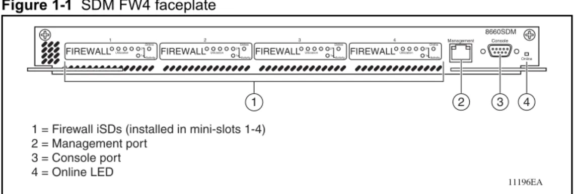
The 8660 SDM has four unique application module slots instead of external I/O ports.
Figure 1-1 shows the faceplate of an SDM FW4. Figure 1-1 SDM FW4 faceplate
Each 8660 SDM application module is available in three different models using a custom-designed general and security processor (Processor PCI Mezzanine Card [PrPMC]) running the Check Point Firewall-1 NG software. The 8660 SDM solution requires that you have at least one Passport 8600 L2-7 Intelligent Routing Switch.
The three 8660 SDM models are:
8660 SDM card with one application mini-slot (mini-slot 4) populated with a firewall iSD (SDM FW1)
8660 SDM card with two application mini-slots (mini-slots 3 and 4) populated with firewall iSDs (SDM FW2)
8660 SDM card with four application mini-slots (mini-slots 1–4) populated with firewall iSDs (SDM FW4)
Table 1-1 lists the 8660 SDM hardware features. Table 1-1 8660 SDM hardware features
Footprint One slot in a Passport 8600 chassis
CPU Intel
RAM 512 Mbytes
Number of iSD slots Four
11196EA
1 = Firewall iSDs (installed in mini-slots 1-4) 2 = Management port 3 = Console port 4 = Online LED Online Console Management 8660SDM 1 2 3 4 FIREWALL 1 Utilization Online Activity 2 1 FIREWALL 2 Utilization Online Activity 2 1 FIREWALL 3 Utilization Online Activity 2 1 FIREWALL 4 Utilization Online Activity 2 1
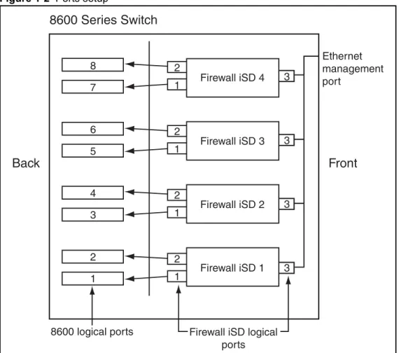
Firewall iSD ports
Each firewall iSD has three Ethernet ports defined. Ports 1 and 2 face the backplane of the 8660 SDM board. Port 3 connects to the management port on the front faceplate of the 8660 SDM. See Figure 1-2.
Figure 1-2 Ports setup
NOTE – The mini-slots on the 8660 SDM are numbered from left to right (1-4). However, the
firewall iSDs are installed from right to left (that is, for an SDM FW1, the firewall iSD is in mini-slot 4; for an SDM FW2, the firewall iSDs are installed in mini-slots 3 and 4, and so on).
1 2 3 3 3 3 2 2 2 1 1 1
Front
Back
8600 Series Switch
Firewall iSD 4 Firewall iSD 3 Firewall iSD 2 Firewall iSD 1 1 2 3 4 5 6 7 88600 logical ports Firewall iSD logical ports
Ethernet management port
Table 1-2 describes the firewall iSD logical ports.
For further information on VLANs, refer to “Passport 8600 and firewall iSD VLANs” on page 28.
NOTE – There are two methods for upgrading software on the firewall iSD. The first method
uses the ASF5100_2.2.7.0_SDM_R55.img file. The second method uses the
ASF5100_2.2.7.0_SDM_R55.pkg file. The .pkg file is currently unavailable. In future up-issues of software, the .pkg file will be available. Additional configuration can be necessary when upgrading using the .pkg method.
Management and serial ports
The Ethernet management port on the 8660 SDM is an MDI 10/100/1000Base-T port
.
The 8660 SDM has one serial port for attaching console devices. The console port provides terminal access to the 8660 SDM for the CLI. The console cable is straight-through, as opposed to null modem.
Both the Ethernet management port and the console port are shared among the iSDs. To access each firewall iSD individually, you must select the active firewall iSD using the Passport 8600 Series Switch CLI. This switches the front-facing console port to manage the firewall iSD of your choice. For information on using the Passport 8600 Series Switch CLI to switch among firewall iSDs on the 8660 SDM, see “Switching management and console ports among iSDs” on page 56.
Table 1-2 Firewall iSD logical ports
Port Description
1 (Control plane) Used strictly for cluster and Check Point management NAAP VLAN (VLAN ID 4094)
Management VLAN
2 (Data plane) Used for data
Used for Check Point sync when High Availability (HA) is enabled Firewall and Firewall Peering VLAN — up to 256 VLANs Sync VLAN
3 (Maintenance) Isolated to the Ethernet management port on the front of the 8660 SDM and the logical Port 3 of the other firewall iSDs.
Used for maintenance
Connects to the management port on the front faceplate of the 8660 SDM
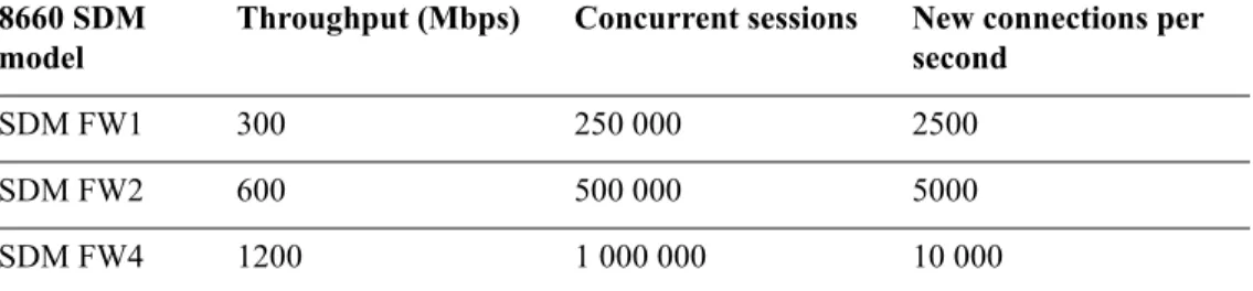
Performance
Table 1-3 shows the hardware performance numbers for the firewall iSD.
Certification
Secured by Open Platform for Security (OPSEC)
System management
Browser-Based Interface (HTTP and HTTPS), as well as CLI (serial, Telnet and Secure Shell [SSH]), offers easy configuration of network settings
Extensive diagnostics
Logging and monitoring
SNMP V2c and V3 event and alarm traps
Large RAM for local logging with periodic transfer to management server
Hard drive for storing log messages
Table 1-3 8660 SDM hardware performance
8660 SDM model
Throughput (Mbps) Concurrent sessions New connections per second
SDM FW1 300 250 000 2500
SDM FW2 600 500 000 5000
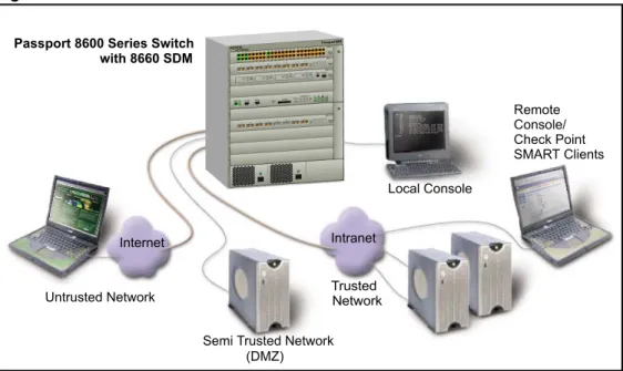
8660 SDM basics
Network elements
Figure 1-3 shows a basic network using the Passport 8600 Series Switch with the 8660 SDM installed in slot 3.
Figure 1-3 Network elements
Networks
Trusted networks
These represent internal network resources that must be protected from unauthorized access. Trusted networks usually provide internal services such as a company’s intranet, as well as valued applications made available to external clients, such as public e-commerce web sites.
Semi-trusted networks
To increase security, services intended primarily for external clients are often placed on a separate network so that a hostile intrusion would not affect the company’s internal networks. A network isolated in this way is also known as a De-Militarized Zone (DMZ). For more information, see your Check Point documentation.
Internet
Passport 8600 Series Switch with 8660 SDM
Local Console
Intranet
Untrusted Network
Semi Trusted Network (DMZ) Remote Console/ Check Point SMART Clients Trusted Network
Untrusted networks
These are the external networks that are presumed to be potentially hostile, such as the Internet.
Firewalls
8660 SDM
The 8660 SDM with firewall iSDs is placed in the path between your various trusted, semi-trusted, and untrusted networks. It examines all traffic moving between the connected networks and either allows or blocks that traffic, depending on the security policies defined by the administrator.
Management interfaces
Local console
A local console is used for entering basic network information during initial configuration. Once the system is configured, the local console can be used to access the text-based Command Line Interface (CLI) for collecting system information and performing additional configuration. The firewall iSD console is not used to manage or install firewall policies.
Remote console/Check Point SMART clients
— For a list of trusted users, the administrator can separately allow or deny Telnet or Secure Shell (SSH) access to the firewall iSD CLI, and HTML or SSL access to the Browser-Based Interface. Remote access features can be used for collecting system information and performing additional configuration, but not to manage or install firewall policies.
— Check Point SMART Client software, such as the SmartDashboard, can be installed on one or more administrator workstations on your network. This software usually provides a graphical user interface (GUI) for creating, modifying, and monitoring firewall policies. For security, SMART Clients do not interact directly with the firewalls. Instead, any policy changes made in a SMART Client are forwarded to the SmartCenter Server, which then loads them onto the firewalls. For convenience, a SMART Client can be installed on the management station running the
SmartCenter Server (see following Note on page 28).
Check Point SmartCenter Server management station
The management station running the SmartCenter Server holds the master policy database for all the firewalls in your network. Its job is to establish Secure Internal
Communications (SIC) with each valid iSD and load the iSD with the appropriate security policies. The SmartCenter Server may be enabled on the iSD in the CLI setup utility.
NOTE – If you have a second firewall iSD in the cluster to implement an active-standby (High Availability [HA]) firewall configuration, you must install the SmartCenter Server on a management station. In this case, do not enable the SmartCenter Server on the firewall iSD
when prompted in Step 11 of the initial setup routine, which starts on page 48.
Passport 8600 and firewall iSD VLANs
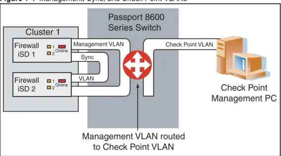
Figure 1-4 shows the Management, Sync, and Check Point VLAN configurations. Figure 1-4 Management, Sync, and Check Point VLANs
Passport 8600
Series Switch
1 2Online 1 2Online Firewall iSD 1 Firewall iSD 2Cluster 1
Management VLAN Sync VLANCheck Point VLAN
Check Point
Management PC
Management VLAN routed
to Check Point VLAN
Table 1-4 describes the Passport 8600 and firewall iSD VLANs. The VLANs can be created using either CLI commands or the Java Device Manager (JDM).
Table 1-4 Passport 8600 and firewall iSD VLANs
VLAN Description
*Management VLAN ID 1 - 4092
Used for management of the iSDs.
Configured on the Passport 8600 Series Switch and on each firewall iSD.
Configured on logical Port 1 of each firewall iSD during device (iSD) initialization.
*Sync VLAN ID 1 - 4092
Used when multiple devices exist in a cluster for synchronization of configurations, software, and session records.
Configured on the iSDs and the Passport 8600 Series Switch. Configured on logical Port 2 of the firewall iSD.
Must have the lowest VLAN ID number configured in the cluster.
**NAAP VLAN (ID 4094)
ID 4094
Used by the Passport 8600 Series Switch for system level manage-ment of the firewall iSD.
Configured on the Passport 8600 Series Switch only.
**Firewall VLAN ID 1 - 4092
L2 bridged VLAN into the firewall iSD (directs traffic in and out of the firewall iSD)
Results in traffic being bridged into the firewall iSD (where routing occurs), and bridged out.
Configured on either the trusted or the untrusted side of the firewall. Maximum of 256 Firewall VLANs on the firewall iSD.
**Firewall Peering VLAN
ID 1 - 4092
Directs traffic in and out of the firewall iSD.
L3 routed VLAN (used to route between the firewall iSD and the Passport 8600 Series Switch (that is, they exchange routing informa-tion)).
Configured on either the trusted or the untrusted side of the firewall. Can be more than one Firewall Peering VLAN per Passport 8600
chassis.
Contains only ports on the 8660 SDM slot.
**Check Point VLAN Used for the Check Point server connection. Recommended that it be in a VLAN by itself. Routed into the Management VLAN.
* Created using the “config cluster” command on the Passport 8600 Series Switch.
The Check Point VLAN is the normal Passport 8600 VLAN used for the Check Point management station. It is not a specific firewall VLAN. In this document, Check Point VLAN is used as a naming convention to easily identify it.
NOTE – Nortel Networks recommends that you avoid using the same VLAN ID for the Sync
VLAN and the Management VLAN.
NOTE – The Sync VLAN must have the lowest VLAN ID of any configured on the firewall
iSD.
Figure 1-5 shows the Firewall VLAN and Firewall Peering VLAN. Figure 1-5 Firewall and Firewall Peering VLANs
Passport 8600
Series Switch
1 2OnlineTrusted VLAN
Bridged or routed
Untrusted VLAN(s)
Bridged or routed
Initial setup
This chapter describes how to perform initial setup for configuration of an 8660 SDM. Basic configuration is performed on the firewall iSD to allow remote access using Telnet or SMART Client. The Check Point management tools are then installed on a workstation.
NOTE – For basic information on preparing the Passport 8600 Series Switch and firewall
modules for initial configuration, see Getting Started (part number 320095-A) and Installing the 8660 Service Delivery Module (SDM) for the Passport 8600 Series Switch (part number 217314-A).
Overview of initial setup tasks
Initial setup involves the following tasks:
Ensuring your network has the basic requirements (page 32)
Using the CLI for basic configuration(page 36)
Basic requirements
The following requirements are needed prior to configuring the firewall iSD:
8660 SDM installed according to directions in Installing the 8660 Service Delivery Module (SDM) for the Passport 8600 Series Switch (part number 217314-A).
Network cables attached, and module powered on and connected to a console terminal.
8660 SDM firewall iSDs running firewall OS version 2.2.7.0 or higher (factory-installed on new units).
A Check Point license for each firewall iSD.
A Check Point license for the Check Point management station, if implemented.
*One subnet assigned for internal firewall iSD use. This subnet must consist of the following IP addresses:
One Management IP (MIP) address. An IP address for the firewall iSD.
A list of subnets that will be statically configured on the iSD for internal networks, plus the IP address of the internal router that handles routes for these networks.
The IP address of the default gateway for data moving through the iSD to the Internet.
An IP address reserved for the iSD on each trusted, untrusted, and semi-trusted subnet that will connect directly to the iSD. (You can create multiple interfaces on a single port. Each interface will have a unique IP address, subnet, vlan association.)
NOTE – *The highest IP address and lowest IP address in the subnet range are reserved for
Example networks
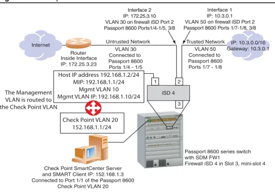
Figure 2-1 shows the example network that is the basis for the procedures that are described in this chapter. Once the network information is collected, you can use the Setup utility to initialize the firewall iSD as described in “Initializing the firewall iSD” on page 44.
In this example, the network spans 192.168.1.0/24. This is an SDM FW1 configuration — the 8660 SDM is in Slot 3 of the Passport 8600 Series Switch. Firewall iSD 4 (in mini-slot 4) is configured in this example. Ensure you have connected the console cable between the serial port on the 8660 SDMand the serial port of a computer with terminal emulation software. Figure 2-1 Example network with the 8660 SDM FW1
Internet
Router Inside Interface IP: 172.25.3.23
Untrusted Network Trusted Network IP: 10.3.0.0/16 Gateway: 10.3.0.1 Interface 1
IP: 10.3.0.1 VLAN 50 on firewall iSD Port 2 Passport 8600 Ports 1/7-1/8, 3/8 Interface 2
IP: 172.25.3.10 VLAN 30 on firewall iSD Port 2 Passport 8600 Ports1/4-1/5, 3/8
Check Point SmartCenter Server and SMART Client IP: 152.168.1.3 Connected to Port 1/1 of the Passport 8600
Check Point VLAN 20
Passport 8600 series switch with SDM FW1
Firewall iSD 4 in Slot 3, mini-slot 4
Note: Firewall iSD modules are inserted from right to left on the 8660 SDM board. That is, an SDM FW1 has one firewall iSD in mini-slot 4 on the 8660 SDM board. An SDM FW2 has two firewall iSDs installed in mini-slots 3 and 4, and so on. Therefore, Ports 1 and 2 of an SDM FW1 correspond to Ports 7 and 8 on the Passport 8600 series switch. Ports 1 and 2 of the firewall iSD in mini-slot 3 correspond to ports 5 and 6 on the Passport 8600 series switch, and so on.
iSD 4 1 2 3 VLAN 30 Connected to Passport 8600 Ports 1/4 - 1/5 VLAN 50 Connected to Passport 8600 Ports 1/7 - 1/8
Check Point VLAN 20 152.168.1.1/24 The Management
VLAN is routed to the Check Point VLAN
Host IP address 192.168.1.2/24 MIP: 192.168.1.1/24
Mgmt VLAN 10 Mgmt VLAN IP: 192.168.1.10/24
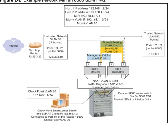
Figure 2-2 shows the example network with an 8660 SDM FW2 installed in slot 3 of the Passport 8600.
Figure 2-2 Example network with an 8660 SDM FW2
The rules for configuring networks and ports are as follows:
You can configure one address per interface, with one network address range.
You can assign multiple interfaces to a port (up to 255).
Each IP interface is configured to represent a network attached to a firewall iSD.
Interfaces on the same port cannot share the same network.
A network device that is connected to an interface must be configured to use the interface IP address as the default gateway. This directs traffic through the iSDs.
Internet
Check Point SmartCenter Server and SMART Client IP: 152.168.1.3 Connected to Port 1/1 of the Passport 8600
Check Point VLAN 20
Passport 8600 series switch Slot 3 - SDM FW2 Firewall iSDs in mini-slots 3 & 4
iSD 4 1 2 3 iSD 3 1 2 3
Check Point VLAN 20 152.168.1.1/24 Host 1 IP address 192.168.1.2/24 Host 2 IP address: 192.168.1.3/24 MIP: 192.168.1.1/24 Mgmt VLAN IP: 192.168.1.10/24 Mgmt VLAN 10 (Master) (Standby) Untrusted Network VLAN 30 (Untrusted) Ports 1/4, 1/5 (on the 8600) 172.25.3.10 Next hop Router 172.25.3.23 Trusted Network VLAN 50 (Trusted) Ports 1/7, 1/8 (on the 8600) 10.3.0.1 Sync VLAN VLAN ID 5 Management VLAN VLAN ID 10 NAAP VLAN ID 4094 Note: Only one NAAP VLAN
is needed per chassis Firewall Peering
Network elements
The network elements are the following:
“Firewall iSD management network” on page 35
“SmartCenter Server” on page 35
“Trusted network” on page 36
“Untrusted network (Internet)” on page 36
Firewall iSD management network
The firewall iSD IP address in the example network is 192.168.1.2 and the Management IP (MIP) address is 192.168.1.1/24.
The MIP must be configured on Port 1 of the firewall iSD. Once configured, that port cannot be assigned to an interface. Use Port 2 (of the firewall iSD) for firewall traffic.
The MIP address supports iSD clustering with a redundant iSD in a high-availability (HA) failover configuration. That is, the Management VLAN can be used to provide sync.
If you have only one iSD in your system, you must still configure the MIP address. NOTE – The management network port is for administrative purposes such as the BBI, Telnet,
SSH, and the Check Point management tools such as the SmartCenter Server and the SMART Client (see “Installing Check Point management tools” on page 62).
NOTE – To provide a secure remote access path for a secondary SmartCenter Server or
SMART Client, you can configure it on the Trusted Network.
SmartCenter Server
You can install the SmartCenter Server on the firewall iSD host (if HA is not enabled) or on a Check Point management station. In the example network, it is implemented on a Check Point management station. The Check Point management station IP address is 152.168.1.3.
NOTE – If you have a second iSD in the cluster to implement an HA firewall configuration,
you must install the SmartCenter Server on a management station. If this is your situation, do not enable the SmartCenter Server on the firewall iSD when prompted in Step 11 of
NOTE – If you previously installed the SmartCenter Server on the firewall iSD, you must first re-image the firewall iSD if you want to install SmartCenter Server on a Checkpoint
management station.
Trusted network
The Trusted Network IP address range is 10.3.0.0/16.
The Trusted Network connects to logical port 2 of firewall iSD 4, which corresponds to logical port 8 on the Passport 8600 Series Switch. This is IP Interface 1. The Interface address is 10.3.0.1.
Untrusted network (Internet)
The default gateway IP address of the firewall iSD is 172.25.3.23. This is the internal interface of the upstream router.
The Untrusted Network connects to logical port 2 of firewall iSD 4, which corresponds to logical port 8 on the Passport 8600 Series Switch. This is IP Interface 2. The Interface address is 172.25.3.10.
Using the CLI for basic configuration
This section describes initial configuration procedures using CLI commands from both the Passport 8600 Series Switch console and the firewall iSD console. For procedures to configure the firewall iSDs using the JDM, see “Using JDM to configure firewall iSDs” on page 93. If you have an SDM FW2 or FW4, you must identify the firewall iSD to be configured. For commands to switch among the firewall iSDs, see “Switching management and console ports among iSDs” on page 56.
New Passport 8600 CLI commands for the 8660 SDM
The following are new commands added to the Passport 8600 CLI to manage the firewall iSD:
“config naap” on page 37
“show naap” on page 37
“config cluster” on page 38
config naap
Table 2-1 shows the available commands and syntax for config naap.
show naap
Figure 2-3 shows an example of the show naap command string. Figure 2-3 Show naap
Table 2-1 Config naap
Command Syntax and Usage connect <dev#> [<NAAP port#>] disable
enable info
minislot-state <enable|disable> <Slot#> [<Mini-Slot#>] set-console <Slot#> <Mini-Slot#>
>Passport-8610 : 5# show cluster Naap Information:
Naap State : Enabled Naap Vlan : 4094
Naap Mac : 00:05:ad:45:66:a6 Naap Inter-Chassis-Link :
Console on Slot 2 : MiniSlot 4 Console on Slot 8 : MiniSlot 4 Naap Peer Devices:
1: HW_ISD:SW_ASF5100 UP/UP Local IP192.168.1.3 SW_IMAGE_VERSION : 2.2.7.0_sdm
Naap Mac: 00:00:50:11:d6:46 - 2/7
2: HW_ISD:SW_ASF5100 UP/UP Local IP192.168.1.2 SW_IMAGE_VERSION : 2.2.7.0_sdm
config cluster
Table 2-2 shows the available commands and syntax for config cluster.
show cluster
Figure 2-4 shows an example of the show cluster command string. Figure 2-4 Show cluster
Table 2-2 Config cluster
Command Syntax and Usage add <Slot#> <Mini-Slot#> create <firewall|ssl|ids|vpn> sync vlan <value>
delete info
mgmt vlan <value>
remove <Slot#> <Mini-Slot#>
NEW 8600 CLI COMMANDS
>Passport-8610:5/config/cluster/1# show cluster
==================================================== SDM Cluster Information
==================================================== ID TYPE SIZE MGMTVLAN SYNCVLAN MEMBERS ---1 firewall 2 ---10 5 (3,---1) (3,2) 2 firewall 2 20 5 (3,3) (3,4) >Passport-8610:5/config/vlan/100# create byport 1 firewall-vlan cluster 1
Modified Passport 8600 CLI commands for the 8660 SDM
The following commands have been modified for the Passport 8600 CLI to manage the firewall iSD:
“config vlan <vid> create” on page 39
“show config module <value>” on page 40
config vlan <vid> create
Table 2-3 shows the available commands and syntax for config vlan <vid> create. Table 2-3 Config vlan <vid> create
Command Syntax and Usage
byport <sid> [name <value>] [color <value>] [naap-vlan] [firewall-vlan] [firewall-peering-vlan] [cluster <value>]
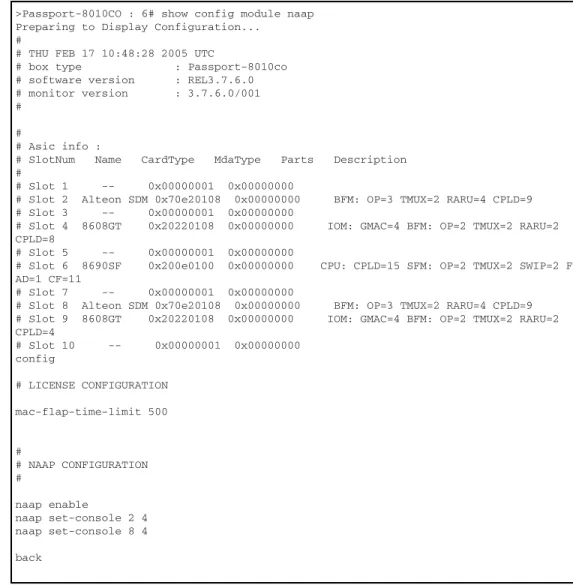
show config module <value>
Figure 2-5 shows an example of the show config module <value> command string. Figure 2-5 Show config module <value>
>Passport-8010CO : 6# show config module naap Preparing to Display Configuration...
#
# THU FEB 17 10:48:28 2005 UTC
# box type : Passport-8010co # software version : REL3.7.6.0 # monitor version : 3.7.6.0/001 #
#
# Asic info :
# SlotNum Name CardType MdaType Parts Description #
# Slot 1 -- 0x00000001 0x00000000
# Slot 2 Alteon SDM 0x70e20108 0x00000000 BFM: OP=3 TMUX=2 RARU=4 CPLD=9 # Slot 3 -- 0x00000001 0x00000000
# Slot 4 8608GT 0x20220108 0x00000000 IOM: GMAC=4 BFM: OP=2 TMUX=2 RARU=2 CPLD=8
# Slot 5 -- 0x00000001 0x00000000
# Slot 6 8690SF 0x200e0100 0x00000000 CPU: CPLD=15 SFM: OP=2 TMUX=2 SWIP=2 F AD=1 CF=11
# Slot 7 -- 0x00000001 0x00000000
# Slot 8 Alteon SDM 0x70e20108 0x00000000 BFM: OP=3 TMUX=2 RARU=4 CPLD=9 # Slot 9 8608GT 0x20220108 0x00000000 IOM: GMAC=4 BFM: OP=2 TMUX=2 RARU=2 CPLD=4 # Slot 10 -- 0x00000001 0x00000000 config # LICENSE CONFIGURATION mac-flap-time-limit 500 # # NAAP CONFIGURATION # naap enable naap set-console 2 4 naap set-console 8 4 back
Configuring the 8660 SDM
Configuring the 8660 SDM requires that you perform configurations at both the Passport 8600 Series Switch console, and at the firewall iSD console. In this example, the configurations are done first from the Passport 8600 Series Switch console. The configuration procedures include all steps to complete initial configuration on an SDM FW1, FW2, or FW4. Optional steps (based on the 8660 model) are identified where applicable.
Using the Passport 8600 Series Switch console, enter the following commands: 1. Create the firewall cluster.
config cluster <cluster-id> create firewall Example:
Passport-8610:5# conf cluster 1 create firewall
2. Add the firewall iSD to a cluster.
config cluster <cluster-id> add <slot> <mini-slot> Example:
Passport-8610:5# conf cluster 1 add 3 4
NOTE – Add a second firewall iSD for a two-member cluster. You must always create a cluster
during initial configuration of the firewall iSD. A cluster contains either one firewall iSD, or two firewall iSDs.
3. Create the Management VLAN.
conf cluster <cluster-id> mgmt vlan <vid> Example:
Passport-8610:5# conf cluster 1 mgmt vlan 10
4. Create the Sync VLAN (required only if the cluster will contain two firewall iSDs).
NOTE – This step is optional. If you plan to cluster firewall iSDs in HA mode, Nortel Networks recommends that you create the Sync VLAN. However, in the single firewall iSD cluster configuration (for example, Figure 2-1 on page 33), it is not necessary to configure the Sync VLAN.
Example:
Passport-8610:5# conf cluster 1 sync vlan 5
5. Create Firewall VLANs for each firewall interface, and add them to the appropriate clusters.
config vlan <vid> create byport <stg-id> firewall-vlan cluster <cluster-id> Example:
Passport-8610:5# config vlan 30 create byport 1 firewall-vlan cluster 1
Passport-8610:5# conf vlan 30 ports add 1/4-1/5
Passport-8610:5# config vlan 50 create byport 1 firewall-vlan cluster 1
Passport-8610:5# conf vlan 50 ports add 1/7-1/8
6. Create Firewall Peering VLANs and add them to the appropriate clusters.
config vlan <vid> create byport <stg-id> firewall-peering-vlan cluster <cluster-id> config vlan <vid>
config vlan <vid> ip create <ip> config ip ospf enable
Example:
Passport-8610:5# config vlan 40 create byport 1 firewall-peering-vlan cluster 1
Passport-8610:5# conf vlan 40
Passport-8610:5# config vlan 40 ip create 192.170.1.10/24 Passport-8610:5# config ip ospf enable
NOTE – Open Shortest Path First (OSPF) is supported only in configurations where there is
one firewall iSD in a cluster. If you plan to have two firewall iSDs in a cluster, omit the OSPF configuration commands.
7. Add the IP address for the Management VLAN on the Passport 8600 Series Switch (192.168.1.10/24).
config vlan <vid> ip create <ip> config vlan <vid> ip ospf enable config ip ospf enable
Passport-8610:5# config vlan 10 ip create 192.168.1.10/24 Passport-8610:5# config vlan 10 ip ospf enable
Passport-8610:5# config ip ospf enable
8. Create the VLAN for the Check Point management server.
config vlan <vid> create byport <stg-id> config vlan <vid> ports add <slot> <port> config vlan <vid> ip create <ip>
config vlan <vid> ip ospf enable config ip ospf enable
Example:
Passport-8610:5# config vlan 20 create byport 1 Passport-8610:5# config vlan 20 ports add 1/1
Passport-8610:5# config vlan 20 ip create 152.168.1.1/24 Passport-8610:5# config vlan 20 ip ospf enable
Passport-8610:5# config ip ospf enable
9. Create the NAAP VLAN for communication between the Passport 8600 and the firewall iSD.
config vlan <vid> create byport <stg-id> naap-vlan Example:
Passport-8610:5# conf vlan 4094 create byport 1 naap-vlan
10. Enable NAAP.
config naap enable Example:
Passport-8610:5/config/naap# enable
11. Identify the firewall iSD.
config naap set-console <slot> <mini-port> Example:
Passport-8610:5# config naap set-console 3 4
After you complete these steps, and if you have a new installation of the firewall iSD software image, connect to the firewall iSD console now to initialize the unit. See “Initializing the firewall iSD” on page 44.
If you must upgrade the firewall iSD software, refer to Chapter 11, “Upgrading the software,” on page 333.
If you must remove the 8660 SDM from the Passport 8600 Series Switch, refer to “Halting disk drives on the 8660 SDM” on page 57.
Initializing the firewall iSD
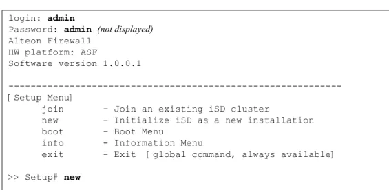
Press Enter on the SDM console terminal to establish the connection. The iSD login prompt appears. Enter the default login name (admin) and the default password (admin). This connects you to the firewall iSD console. If the firewall iSD is set to factory defaults, a special Setup utility menu appears. See Figure 2-6 on page 44.
NOTE – Initialization is only required on the first firewall iSD of a cluster. If you are adding a
second firewall iSD to a cluster, enter the join command rather than new. For instructions to add a second firewall iSD to a cluster using the Setup utility, see “Using the join command” on page 50.
NOTE – Before upgrading the software on the iSD, you must perform the initial setup procedures as explained in this chapter. Once initial setup is complete, see Chapter 11, “Upgrading the software,” on page 333 for more information.
Figure 2-6 Firewall iSD Setup utility menu
login: admin
Password: admin (not displayed)
Alteon Firewall HW platform: ASF
Software version 1.0.0.1
---[Setup Menu]
join - Join an existing iSD cluster
new - Initialize iSD as a new installation boot - Boot Menu
info - Information Menu
exit - Exit [global command, always available] >> Setup# new
Using the Setup utility
The following procedure is an example of the Setup utility prompts and user input for configuration. Follow the example to initialize a new installation. After answering the various Setup questions, the Check Point software is initialized.
NOTE – The IP addresses used in the following steps are taken from the example network on
page 33. Enter information for your specific network configuration. 1. Select a “new” installation.
2. Enter the port number to be used for the management network.
Port 1 must be used for management with this release.
3. Enter the host IP address for this firewall iSD:
There is one host IP address for each firewall iSD. This is the IP address you want to assign to the firewall iSD.
4. Enter the network mask for the entire subnet:
5. Enter the Management VLAN ID.
This Management VLAN must have the same VLAN ID as the Management VLAN created on the Passport 8600 Series Switch. See “Create the Management VLAN.” on page 41.
>> Setup# new
Setup will guide you through the initial configuration of the iSD.
Enter port number for the management network [1-3]: 1
Enter IP address for this machine: 192.168.1.2
Enter network mask [255.255.255.0]: 255.255.255.0
6. Enter the Management IP (MIP) address information.
These addresses must be in the subnet.
7. Set your time zone by selecting continent or ocean, then country, then region.
For example:
Enter the Management IP (MIP) address: 192.168.1.1 Making sure the MIP does not exist...ok
Timezone setting 1 - Africa 2 - Americas 3 - Antarctica 4 - Arctic Ocean 5 - Asia 6 - Atlantic Ocean 7 - Australia 8 - Europe 9 - Indian Ocean 10 - Pacific Ocean
Select a continent or an ocean: 2 Countries:
1 - Anguilla 18 - Ecuador 35 - Paraguay 2 - Antigua & Barbuda 19 - El Salvador 36 - Peru
3 - Argentina 20 - French Guiana 37 - Puerto Rico 4 - Aruba 21 - Greenland 38 - St Kitts & Nevis 5 - Bahamas 22 - Grenada 39 - St Lucia
6 - Barbados 23 - Guadeloupe 40 - St Pierre & Mique 7 - Belize 24 - Guatemala 41 - St Vincent 8 - Bolivia 25 - Guyana 42 - Suriname
9 - Brazil 26 - Haiti 43 - Trinidad & Tobago 10 - Canada 27 - Honduras 44 - Turks & Caicos Is 11 - Cayman Islands 28 - Jamaica 45 - United States 12 - Chile 29 - Martinique 46 - Uruguay 13 - Colombia 30 - Mexico 47 - Venezuela 14 - Costa Rica 31 - Montserrat 48 - Virgin Islands (U 15 - Cuba 32 - Netherlands Antil 49 - Virgin Islands (U 16 - Dominica 33 - Nicaragua
17 - Dominican Republic 34 - Panama Select a country: 45
8. Set the current date and time:
9. Generate a new Secure Shell (SSH) host key for use with secure remote administration sessions:
Nortel Networks recommends that you generate a new SSH key to maintain a high level of security when connecting to an iSD using an SSH client.
Regions:
1 - Adak Aleutian Islands 2 - Anchorage Alaska Time
3 - Boise Mountain Time - south Idaho & east Oregon 4 - Chicago Central Time
5 - Denver Mountain Time
6 - Detroit Eastern Time - Michigan - most locations 7 - Honolulu Hawaii
8 - Indiana/Knox Eastern Standard Time - Indiana - Starke County 9 - Indiana/Marengo Eastern Standard Time - Indiana - Crawford County 10 - Indiana/Vevay Eastern Standard Time - Indiana - Switzerland Cnty 11 - Indianapolis Eastern Standard Time - Indiana - most locations 12 - Juneau Alaska Time - Alaska panhandle
13 - Kentucky/Monticello Eastern Time - Kentucky - Wayne County 14 - Los_Angeles Pacific Time
15 - Louisville Eastern Time - Kentucky - Louisville area 16 - Menominee Central Time - Michigan - Wisconsin border 17 - New_York Eastern Time
18 - Nome Alaska Time - west Alaska
19 - North_Dakota/Center Central Time - North Dakota - Oliver County 20 - Phoenix Mountain Standard Time - Arizona
21 - Shiprock Mountain Time - Navajo
22 - Yakutat Alaska Time - Alaska panhandle neck Select a region: 17
Enter the current date (YYYY-MM-DD) [2004-01-05]:<Enter to accept default>
Enter the current time (HH:MM:SS) [13:14:09]:<Enter>
Generate new SSH host keys (yes/no) [yes]: y This may take a few seconds...ok
10. Set the new administrator password.
The current default administrator password is admin. Nortel Networks recommends that you change the password.
11. Choose whether to enable the Check Point SmartCenter Server on the firewall iSD.
NOTE – The first time you initialize a firewall iSD, you are presented with the Check Point
SmartCenter Server options as described in this Step. If you have previously initialized the firewall iSD, these options will not appear. If you wish to repeat the initialization process, including enabling the Check Point SmartCenter Server, you must first re-install the firewall iSD software.
Setup gives you the option of configuring your firewall iSD with or without a co-located SmartCenter Server. Enabling the SmartCenter Server on the management interface lets you use the interface without requiring Secure Internal Communications (SIC) and without a second license required for hosting the SmartCenter Server on the management station. However, you cannot take advantage of this feature if you intend to install a second firewall iSD in a cluster with this one. In that case, you must enter 1at the prompt and install the SmartCenter Server on the management station.
For Check Point NG with Application Intelligence software, Setup provides two options (selections 3 and 4) that support Check Point Express licensing. See Check Point documentation for more information on Check Point Express.
NOTE – If you install the SmartCenter Server on the firewall iSD now, but decide later to add a second firewall iSD to the cluster (to implement an HA firewall iSD configuration), you must re-image your system and repeat Setup to uninstall the SmartCenter Server.
Enter a password for the "admin" user: <password>
Re-enter to confirm: <password>
Select installation type: 1. Check Point Gateway
2. Check Point Gateway and SmartCenter Server 3. Check Point Gateway Express
4. Check Point Gateway Express and SmartCenter Server Enter your selection: (1/2/3/4) [1]:
12. If you chose 2 or 4 in Step 11 on page 48, enter the management server administrative password.
13. If you chose 1 or 3 in Step 11 on page 48, you will be prompted to set the Check Point SIC one-time password.
The SIC password is required later when you establish SIC between an external Check Point management station and a firewall iSD. Check Point documentation refers to this password as the “Authentication Key” (see page 79).
14. Allow self-configuration to complete.
Once the basic configuration information has been entered, the system begins a phase of self- configuration and initialization. During this phase, a series of messages are displayed. The self-configuration phase is complete when the following message is displayed:
The firewall iSD you have initialized reboots at the end of the self-configuration phase. To install the Check Point license, see “Setting the license key” on page 54.
Enter Check Point Primary SmartCenter Server admin password:
<password>
Re-enter to confirm: <password>
Enter onetime SIC password: <SIC password>
Re-enter to confirm: <SIC password>
Applying Check Point firewall and SmartCenter Server settings... Initializing system...ok
Configuring firewall...Done
Setup successful. Relogin to configure. login: