Adaptive Iterative Decoding:
Block Turbo Codes
and Multilevel Codes
A thesis submitted in fulfilment of the requirements for the Degree of
Doctor of Philosophy
in Electrical and Electronic Engineering from the University of Canterbury
· Christchurch, New Zealand
Philippa Anne Martin
B.E. (Hons 1)
ENGINEERING liBRARY
IK
5/o:l.~b
.M38:L
2DO(
Abstract
New adaptive, iterative approaches to the decoding of block Thrbo codes and mul-tilevel codes are developed. Block Turbo codes are considered as they can readily provide high data rates, low decoding complexity and good performance. Multilevel codes are considered as they provide a moderate complexity approach to a high complexity code and can provide codes with good bandwidth efficiency.
The work develops two adaptive sub-optimal soft output decoding algorithms for block Turbo codes. One is based on approximation and the other on the dis-tance properties of the component codes. They can be used with different codes, modulation schemes, channel conditions and in different applications without mod-ification. Both approaches provide improved performance compared to previous approaches on the additive white Gaussian noise (A WG N) channel. The approxi-mation based adaptive algorithm is also investigated on the uncorrelated Rayleigh fiat fading channel and is shown to improve performance over previous approaches. Multilevel codes are typically decoded using a multistage decoder (MSD) for complexity reasons. Each level passes hard decisions to subsequent levels. If the approximation based adaptive algorithm is used to decode component codes in a tra-ditional MSD it improves performance significantly. Performance can be improved further by passing reliability (extrinsic) information to all previous and subsequent levels using an iterative MSD. A new iterative multistage decoding algorithm for multilevel codes is developed by treating the extrinsic information as a Gaussian random variable. If the adaptive algorithms are used in conjunction with itera-tive multistage decoding on the AWGN channel, then a significant improvement in performance is obtained compared to results using a traditional MSD.
Acknowledgments
I would like to thank all the people who have helped and supported me throughout my PhD. I would especially like to acknowledge and thank my supervisor Professor Desmond Taylor for his patience, guidance, endless proof reading and support. I am also grateful to Des for providing funding for me to attend the 2nd International Symposium on Turbo Codes and Related Topics in France and Globecom 2000 in the United States of America.
I wish to acknowledge the public good science fund and Marsden fund of New Zealand for their financial support. Also Consultel and the University of Canterbury for their scholarships during my undergraduate and postgraduate studies.
I would like to thank Aaron Gulliver, Robert van Nobelen and Brian Hart for being willing to answer technical questions. I wish to acknowledge and thank Annie Picart and Ramesh Pyndiah for helping me reproduce their results. I am also grateful to Ben Skelton and Anthony Griffin for the LaTeX style files they gave me. I would also like to thank Mike Shurety, Dave van Leeuwen, Florin Predan and Pieter Kikstra for all their help over the years.
My utmost thanks to all my friends who helped keep spirits up. Thanks Bronwyn and John Ward, Rachel Johnston, Darryl Anderson, Cressida Harding, Jon Cherrie, Gerard van Soest, Elisabeth Nock, Torrie Moore and Jonathon Kong. Thanks also to the "comms lab" residents who answered research and latex ques-tions, tried to educate me about rugby and helped keep life cheerful (Monkee's friday's will be a fond memory). Thanks Katharine Holdsworth, Wing Seng Leon, Anthony Griffin, Peter Green, Ben Jones, Ben Skelton, Andrew Reid, Aarne Mam-mela, Jukka Mannerkoski, Richard Clarke, Mary Nash, Karen Barton and Casey Miller.
encouragement. I would especially like to thank my parents for bringing me up to believe that I could achieve anything that I wanted to.
Most of all I would like to thank David Rankin for his emotional support, ability to make me laugh, and willingness to answer my questions or be a sounding board at all hours. Thank you for helping me through the bad times and celebrating the good times with me.
The University of Canterbury February 2001
Contents
Abstract
Acknowledgments
Chapter 1 Introduction
1.1 Introduction . 1. 2 Background .
1.2.1 Additive White Gaussian Noise Channel 1.2.2 Rayleigh Fading Channel .
1.3 Thesis Content . . . 1.4 Thesis Contributions
1.4.1 Contributions to Block Turbo Coding . 1.4.2 Contributions to Multilevel Coding 1.4.3 Publications . . . .
Chapter 2 Background Information
2.1 Introduction . . . . 2.2 Primitive Binary BCH Codes
2.2.1 Encoder . . . .
2.2.2 Hard-Input Hard-Output Decoder . 2.2.3 Soft-Input Hard-Output Decoders . 2.3 Block Turbo Codes . . . .
2.3.1 Non-adaptive Reduced-Complexity SISO Decoder 2.3.2 Adaptive Reduced-Complexity SISO Decoders 2.4 Multilevel Coding and Multistage Decoding . . .
2.4.1 Multilevel Encoder, Code Design and Partitioning .
2.4.2 Multistage Decoder . . . . 2.4.3 Iterative Multistage Decoder .
36 38 2.5 Summary . . . 40 Chapter 3 Adaptive Iterative Decoding of Block Turbo Codes 41
3.1 Introduction . . 41
3.2 Derivation of
a
423.2.1 Scaling and Termination Criteria 45
3.3 Adaptive Approaches to Estimating f3 . 46
3.3.1 Approximation Based Approach . 48
3.3.2 Distance Based Approach 56
3.4 Simulation Results . . . 60
3.4.1 Approximation Based Approach to Estimating f3 3.4.2 Distance Based Approach to Estimating f3
60 77 3.5 Conclusions . . . 82 Chapter 4 Multilevel Coding and Iterative Multistage Decoding 85
4.1 Introduction . . . 85
4.2 Iterative Multistage Decoder . 87
4.3 Adaptive Component Decoder 93
4.4 Simulation Results . 97
4.5 Performance Bound : 117
4.6 Conclusions 119
Chapter 5 Block Turbo Codes on the Uncorrelated Rayleigh Flat
Fading Channel 121
5.1 Introduction .
5.2 Adaptive Iterative Decoding
5.2.1 Without Channel State Information . 5.2.2 With Channel State Information 5.3 Simulation Results . . . .
5.3.1 Without Channel State Information . 5.3.2 With Channel State Information
5.4 Conclusions . . . . Chapter 6 Conclusions and Suggestions for Future Work
6.1 Introduction . 6.2 Conclusions . 6.3 Future Work .
6.3.1 Error Correction Coding/ Decoding . 6.3.2 Equalization .
6.3.3 Summary ..
Appendix A Block Turbo Codes A.1 Introduction . . . .
A.2 Block Thrbo Codes
A.3 Serial Concatenated Codes A.4 Parallel Concatenated Codes . A.5 Discussion and Conclusions .
Appendix B Binary Linear Block Codes B.1 Introduction . . . . B.2 Perfect and Quasi-Perfect Codes . B.3 Encoder . . . .
B.4 Decoder and Dual Codes
Appendix C Performance Bounds for Block Turbo Codes C.1 Extended BCH Component Codes ..
Appendix D Glossary of Abbreviations Appendix E Glossary of Symbols
Bibliography
0 • • • • . 133
135
135 135 138 139 142 146149
. 149 . 149 152 154 155157
157 157 158 . 159161
. 161165
167
Chapter 1
Introduction
1.1 Introduction
The number and expectations of wireless users and the demand for limited resources such as bandwidth are increasing rapidly. In order to allow voice, real-time video, internet and banking services to be provided on a mobile phone a variety of difficult engineering problems need to be solved [97].
In order to fully utilize the limited channel resources available and approach the capacity [100] of the channel the components of a communication system must be optimized. The main components in a communication system are source and error correction coding/ decoding, modulation/ demodulation, pulse shaping/ matched filtering and equalization as shown in Fig. 1.1. The purpose of each component will be discussed in section 1.2.
Designing a communication system is all about tradeoffs. For example, if the error correction coding/ decoding provides a 3dB performance gain, the gain can be used to double the data throughput, halve the broadcast power, reduce the antenna diameter by 30% or increase the transmission distance by 40% [2]. The most common tradeoffs in transmitter and receiver design are among bandwidth, power, complexity, cost, delay, error performance and data rate.
Information To be Transmitted
Estimate of Transmitted Information
Source Encoder
Error Correction
Encoder
Error Correction
Decoder
Receiver
Pulse Shaper and Modulator
Demodulator and Equalizer
Figure 1.1: A communication system.
capacity1. The codes and decoding algorithms will be designed for the additive white
Gaussian noise (AWGN} channel and the uncorrelated Rayleigh flat fading channel. Multilevel coding will be used to create powerful codes in a moderate complexity, bandwidth efficient manner. An iterative multistage decoder (MSD) is developed in this thesis to decode multilevel codes. It is used to provide a good compromise between complexity and performance. In addition two adaptive sub-optimal
soft-input soft-output (SISO) decoding algorithms based on [90] are developed. These algorithms make the complexity of SISO decoding long block codes feasible, they can adapt to varying channel conditions, treat good and bad blocks differently, and can be used with different codes, modulation schemes and applications. High code rates are achieved by using long block codes in both block Turbo/ product code structures and in multilevel code structures.
1.2
Background
The basic goal of telecommunications engineering is to transmit and receive data over a channel with an error rate below a predefined value. There are many components required in a communication system to achieve this goal. In addition it is desirable to use as little bandwidth, power, time, money and complexity as possible.
The first component in the transmitter is the source encoder as shown in Fig.
1.1. It is used to reduce redundancies in the binary information to be transmitted [44]. This process is reversed at the end of the receiver by the source decoder. In this thesis it is assumed that the input to the error correction encoder has already been through a source encoder, which has produced equiprobable symbols.
Modulation is used to convert the encoded data to a form more suitable for transmission over a channel. It maps an encoded data stream to a predefined con-stellation of points. It also shifts the signal to the correct frequency for transmission after pulse shaping. The frequency, phase or amplitude of the carrier wave may be used to transmit the information. Demodulation is the reverse process to modula-tion.
Two linear modulation schemes are considered in this thesis: M-ary quadra-ture amplitude modulation (QAM) and 111-ary phase shift keying (PSK). M-ary QAM transmits information using different amplitudes in both the in-phase and quadrature dimensions. The resulting constellation has M points on a grid. Square M-ary QAM constellations are considered in this thesis. They use
..JM
amplitudes in each dimension as shown in Fig. 1.2 (each dimension transmits a ..JM-ary ampli-tude shift keying (ASK) signal). M-ary QAM trades off power for bandwidth. The M-ary QAM signal can be written as [85]sm(t)
arh(t)
cos(21rfct)
aqh(t)
sin(21rfct),
0 ~t
~ Ts, m = 1,2, · · · , 111(1.1) where
a
1 andaq
are the amplitudes in the inphase and quadrature dimensionsrespectively,
h(t)
is the pulse shape, Ts is the symbol period andfc
is the carrier frequency.•
•
•
•
•
• • •
• •
• •
• •
•
•
Figure 1.2: M-ary QAM constellation for M 16.
equally spaced around a constant energy circle as shown in Fig. 1.3. The lvf-ary PSK2 signal can be written as [84]
sm(t)
=
h(t)cos(~(m-1))
cos(2rrfct) h(t)sin(~;(m-1))
sin(2rrfct) (1.2)where m = 1,2,·· · ,M and 0 ~
t <
T8 •,_-- ... !~" ' •
I \
I \
I \
I I
\ I
\ I
'e..
.... ____
... JilFigure 1.3: M-ary PSK constellation for M 4 (QPSK).
If a sequence of constellation points was transmitted without pulse shaping, then too much bandwidth would be used. Pulse shaping is used to shape the trans-mitted signal into a band limited form. In an ideal world the minimum amount of bandwidth would be used (a rectangular spectrum). However, this would require the transmission of an infinite duration sine pulse. Also in practise it is difficult to build filters with a sharp rolloff. Often raised cosine or square root raised cosine pulse shapes are used as they offer a range of tradeoffs between the required bandwidth and the filter rolloff. Modulation in conjunction with pulse shaping allows data to be transmitted at the desired frequency in a bandwidth efficient way.
The resulting signal is then transmitted over a channel. The channel can corrupt the transmitted signal with additive noise and can introduce multiplicative distortion due to multi path fading or intersymbol interference
(181).
Error correction coding/ decoding, matched filtering and equalization are added to the communica-tion system to assist in recovering the transmitted signal as shown in Fig. 1.1. A filter matched to the transmitted pulse shape (the matched filter) is used in the receiver to maximize the peak pulse signal to noise ratio (SNR) [47].Error correction coding/ decoding is required because the channel can cause errors in the received signal. The error correction encoder adds structured redun-dancy (non-data symbols) to the data to be transmitted. The structured redunredun-dancy
2Two commonly used PSK constellations are binary PSK (BPSK) which consists of M 2
points and quadrature PSK (QPSK) which consists of M = 4 points. A QPSK constellation
is used by the error correction decoder to detect and/ or correct errors in the re-ceived demodulated data. The receiver can then reduce the number of errors in the estimate and/ or request that data blocks in error be retransmitted. Error correction coding and decoding will be discussed in more detail in chapter 2.
Error correction coding and modulation can be designed together by using multilevel coding [16, 52, 82, 119]. For complexity reasons multilevel codes are usually decoded using a MSD. Multilevel codes and MSDs will be considered in more detail in chapter 2.
Equalization is used to try to reverse the ISI introduced by the channeL It does this by using the statistics of the received signal and any other knowledge available about the channel
(channel state information{CSI)).
The design criteria for the error correction coding/ decoding and equalization depend on the channel and how it corrupts the transmitted signaL In this thesis the memoryless AWGN channel and the uncorrelated Rayleigh flat fading channel are considered.
1.2.1
Additive White Gaussian Noise Channel
The A\VGN channel is typical for satellite and deep-space communications
[69).
On the memoryless AWGN channel the received signal is corrupted by an additive Gaussian random variable with zero mean and two-sided power spectral density
N
0/2.
The noise produces random errors in the received signaL Error correctioncoding/ decoding is used to detect and/ or correct these random errors. The received signal can be written as a function of time as
r(t)
=s(t)
+
g(t)
(1.3)where
s(t)
is the transmitted signal andg(t)
is the AWGN signal. When sampled at the symbol rate, the zth received sample (at timet= lT8 ) is rz = s1+g
1, where Sz is thezth transmitted symbol and g1 is the zth independent AvVGN sample. The probability density function of the zth received sample,
r
1, given thats
1 was transmitted is given by[69]
1
(-lrt-stl
2)where
O";
is the noise variance. This expression will be used by the error correction decoder to determine if s1 was transmitted. As a function of s1 it is known as alikelihood.
The best performance possible is called capacity, it was defined for the AWGN channel by Shannon in [100]. His channel coding theorem states that an arbitrarily small probability of error can be achieved at all rates less than capacity [69]. In [32] a rate 1/2 low density parity check code of block length 107 is stated to be within 0.036dB of capacity at a BER of 10-6• In this thesis codes with shorter block lengths
( <
104) and generally with higher code rates will be considered. The capacity of a bandlimited AWGN channel with an input signal that is bandwidth and average power limited is given by [84, 116]( Pav)
C = B log2 1
+
B No bits/second (1.5)where B is the channel bandwidth, Pav is the average transmitted signal power and
Pav/(BN0 ) is the SNR. As the channel bandwidth tends to infinity the capacity
approaches its asymptotic value of [84, 116]
lim C
~
1.44 P.N.av.B-too 0 (1.6)
1.2.2 Rayleigh Fading Channel
When a radio signal is transmitted it may experience reflection, diffraction, scat-tering or a combination of these3. This results in more than one version of the
transmitted signal being received. Each version has travelled a different path and typically has a different phase, delay, Doppler frequency shift and attenuation. This leads to constructive and destructive interference, this effect is called fading [97].
The A\VGN channel corrupts the transmitted signal with AWGN. The Rayleigh fading channel corrupts the transmitted signal with multiplicative fading and A\VGN. The multiplicative fading is usually modelled as a complex Gaussian random process with zero mean. Its envelope has a Rayleigh distribution, which is given by [104]
(1.7)
3Refiection occurs when the wavelength of the transmitted signal is small compared to the
Fig. 1.4 shows that the amplitude of the multiplicative fading can increase or decrease dramatically. This varies the signal strength and means that the channel has a time varying SNR. In deep fades the noise power can exceed the strength of the faded signal. As a result a large percentage of symbols received during a deep fade can be decoded in error. This results in the Rayleigh fading channel suffering from error bursts in addition to the random errors caused by the AWGN. Therefore, error correction codes are required to correct both error bursts and random errors. Most error correction codes are designed to correct random errors. As a result interleav-ing/ deinterleaving is often used to break up the error bursts4 before error correction
decoding. Equalization and channel estimation techniques [70] are often used to try and reverse some of the channel corruption before error correction decoding. The channel's correlation is exploited during equalization and channel estimation and so any deinterleaving used should be performed after the equalization, but before the error correction decoding.
10
ij
'-' -10
.g
8
:a-20
~
o-30~
-40 -50
-60~----~~---L---~---~----~
0 200 400 600 800 1000
Samples
Figure 1.4: Amplitude of a Rayleigh fading variable.
A transmitted symbol will propagate to the receiver using a number of dif-ferent paths, which may have difdif-ferent delays. The span of path delays is called the
4How random the errors are after interleaving/ deinterleaving depends on the length of the error
maximum excess delay5, Tm [72, 102]. If the symbol is spread in time to occupying
more than a symbol period, Tm
>
T8 , then the channel is called frequency-selective.In this case different frequencies in the transmitted signal will experience different attenuations and phase shifts, and the channel induces lSI [104]. If all versions of a transmitted symbol arrive within a symbol period, Tm
<
T8 , then the channel iscalled frequency non-selective or flat. The flat fading channel does not induce lSI and all frequencies in the transmitted signal experience the same attenuation and phase shift [104].
A fading channel is also characterised as experiencing slow or fast fading. Fast fading occurs when the channel characteristics may vary significantly within
the duration of a symbol. Slow fading occurs when the channel characteristics vary little during the duration of a symbol. The coherence time, T0 , is used to define
the speed of the fading. It is the expected time in which the channel's response is almost invariant [102]. The fading is fast if T0
<
Ts and slow if T0>
T8 [102].In chapter 5 the uncorrelated Rayleigh flat fading channel is considered. The received signal from an uncorrelated Rayleigh flat fading channel can be written as
[8, 83]
r(t)
='Y(t)s(t)
+
g(t),
(1.8)
where
'Y(t)
=
/'A(t)eiB(t)
is the multiplicative fading,'YA(t)
is the magnitude of the fading, j =.J=I
andO(t)
is the phase of the fading[8].
If the fading is slow enough, then it can be assumed thatO(t)
can be estimated and compensated for[8].
In this case coherent demodulation may be assumed and the received signal can be simplified to[83]
r(t)
='YA(t)s(t)
+
g(t),
(1.9)
Recall that the instantaneous SNR varies on the Rayleigh fading channel. Therefore, the average capacity of the Rayleigh fading channel is considered. When the average SNR, r, is greater than two the average capacity is defined as [58, 116] (C)= Blog2(exp(1)) exp( -1/r) ( -£
+
log(r)+
~)
(1.10)where log(·) is the natural logarithm, log2 (·) is the base-2 logarithm and£ is Euler's constant. Since the instantaneous SNR varies with time, the instantaneous capacity
can be. quite different from the average capacity. As a result the average channel capacity of the Rayleigh fading channel is worse than that of the Gaussian chan-nel. But when the channel bandwidth tends to infinity the channel capacities are asymptotically equal and the average channel capacity becomes [58, 116]
lim
(C)
~
1.44 PavB-+oo No (1.11)
The difference between the capacity of the Rayleigh fading channel and the AvVGN channel is::::::: 4dB for uncoded BPSK [116]. At an error rate of 10-4 BPSK performance on the Gaussian channel is only ::::::: 4dB from capacity, while its per-formance on the Rayleigh fading channel is~ 22dB from capacity [116]. Therefore, there is potential for larger coding gains on the Rayleigh fading channeL
1.3 Thesis Content
In Chapter 2 the key background information on error correction coding and multi-level coding is introduced and a literature survey of the area is provided. Chapter 2 introduces the sub-optimal SISO decoding algorithm of [90] and iterative multistage decoding as powerful reduced complexity decoding techniques. It also highlights the need for a flexible adaptive approach to sub-optimal SISO decoding and a new approach to iterative multistage decoding.
optimum results. In addition the parameters treat good and bad received blocks the same way, and they do not adapt to varying channel conditions.
In chapter 3 two new adaptive sub-optimal 8I80 decoding algorithms based
on [88, 90] are developed. One approach is based on approximation and the other
on the distance properties of the component codes. Both approaches estimate the two sequences of parameters on a block-by-block basis. Therefore, good and bad received blocks can be treated differently, the algorithm can adapt to varying chan-nel conditions and the sequences of parameters do not need to be optimized using repeated simulations for different codes, modulation schemes, channel conditions or applications. The new algorithms will be derived by considering the extrinsic in-formation to be a Gaussian random variable [14, 15, 21], rather than as a priori information [21, 43], as this is found to result in better performance.
Two important design criteria for a communication system are bandwidth efficiency and complexity. Multilevel coding combines error correction coding and modulation to provide a bandwidth efficient system. It also allows complicated codes to be created in a low complexity manner. For complexity reasons they are typically decoded using a M8D, which passes hard decisions to subsequent levels (a traditional MSD). However, by using hard decisions, information is being lost. In addition the component decoders never use the information gained from decoding subsequent levels. Performance can be improved by passing soft information to both previous and subsequent levels [27, 53, 71, 73, 74, 121]. Many of the previous approaches do not pass reliability information back to all previous levels [27, 73, 7 4] and use interleaving between some of the component encoders and the channel mapping [27, 73, 74, 121]. Interleaving can increase the encoding and decoding delay and so should be avoided when not needed.
and without interleaving.
The decoding algorithm of [79, 90) is not well suited for use in the iterative MSD developed in chapter 4. In an iterative MSD the magnitude of the extrinsic information passed to other levels must be correct. If the algorithm of [79, 90) is to be used, then a joint optimization of the two precomputed sequences of parameters used on every level is required using repeated simulations. This does not allow for varying conditions, and good and bad blocks are treated the same way. In [77, 79) the received signal is mapped so that the input to each level is centred on two possible values6• Information about the labelling bits from other levels is not known
when this mapping technique is used and this information is required by the iterative MSD.
The adaptive approaches of chapter 3 avoid these restrictions by calculat-ing the sequences of parameters on a block-by-bock basis. The notation for these adaptive approaches is extended in chapter 4 for use in an iterative MSD and with different constellations. The new notation calculates the soft input and output log likelihoods using the constellation points, which avoids the mapping of [79).
One of the adaptive SISO decoding algorithms of chapter 3 is used on the uncorrelated Rayleigh flat fading channel in chapter 5. Simulation results are pre-sented for when ideal or no CSI is available. Finally conclusions and suggestions for future work are discussed in chapter 6.
1.4 Thesis Contributions
This thesis contains original contributions to the fields of block Turbo coding and multilevel coding.
1.4.1
Contributions to Block Turbo Coding
Two adaptive sub-optimal SISO decoding algorithms for block codes are developed in chapter 3. They can be used as component SISO decoders in an iterative decoder for block Turbo codes. One decoding algorithm is based on approximation (
approx-6This means that the algorithm must be modified (a new mapping developed) when different
imation approach) and the other on the distance properties of the component codes (distance approach). The notation is extended for use in an iterative MSD and with different constellations in chapter 4. The adaptive approaches are used for signals transmitted on the AWGN channel in chapter 3 and chapter 4. The approximation approach is used for signals transmitted on the uncorrelated Rayleigh flat fading channel in chapter 5. These approaches are more flexible and improve performance over the precomputed approach of [54, 90].
1.4.2
Contributions to Multilevel Coding
In chapter 4 a new approach to iterative multistage decoding is developed that passes extrinsic information to all previous and subsequent code levels. It treats the extrinsic information passed between levels as a Gaussian random variable, rather than as a priori information. The Gaussian approach is found to perform better than the a priori approach in the simulations of chapter 4. The adaptive algorithms improve performance over [79, 90] when a traditional MSD is used. When the approximation based adaptive algorithm is used in the new iterative MSD it performs significantly better than in a traditional MSD.
1.4.3 Publications
Some of the research presented in this thesis has been presented in the following published papers
•
A. Martin and D. Taylor, "On Adaptive Reduced-Complexity Iterative Decoding", Globecom, San Francisco, USA, 2000 [65].• A. Martin and D. P. Taylor, "On Iterative Multistage Decoding", 2nd Inter-national Symposium On Turbo Codes and Related Issues, Brest, France, 2000 [66].
and the following submitted papers
Chapter 2
Background Information
2.1
Introduction
This chapter covers the relevant background information on error correction coding, error correction decoding, multilevel coding and multistage decoding. It focuses on codes and coded signals transmitted on the additive white Gaussian noise (A WG N) channel, but it is noted that they can also be transmitted on fading channels1 [54, 90].
There are two main categories of error control codes, namely convolutional and block codes [69, 120]. A convolutional code encodes a data stream into a single codeword. A block code splits the data stream into blocks of length k. Each length k block is then encoded. In this thesis block codes will be considered as they can provide good performance at high code rates.
There are many types of block codes [69, 120]. Bose-Chaudhuri-Hocquenghem (BCH) codes are one of the most powerful subclasses of block codes [69, 120] and in-cludes all perfect codes [69]. They are cyclic codes which can encode either binary or non-binary data, and can correct multiple errors [69]. In this thesis primitive binary BCH codes are considered. They are binary linear block codes and are described in section 2.2. A hard-input hard-output (HIHO) decoder for BCH codes is described in section 2.2. However, performance can be improved by using the reliability in-formation contained in the received signal. Soft-input hard-output (SIHO) decoders use this information and are considered in section 2.2. A reduced complexity SIHO
1However, the code design criteria for fading channels are different from those for the AWGN
decoder is considered, which allows long BCH codes to be decoded with manageable decoding complexity.
Many concatenated code structures have been developed to construct power-ful codes using a number of component codes. Early concatenated structures include product codes [23] and two stage concatenated codes as shown in Fig. 2.1 (the outer code was typically a powerful
Reed Solomon (RS)
code2) [29, 69]. These structureswere able to provide good performance by using powerful component codes. The concatenated codes were typically decoded in stages as shown in Fig. 2.1 and so the decoding complexity was dependent on the complexity of the component codes (making it manageable). Both of these concatenated structures pass information from the inner decoder to the outer decoder(s). If the inner decoder is a
soft-input
soft-output (SISO)
decoder, then the outer decoder can be a soft input decoder and can use the received signal and the information gained by the inner decoder (called extrinsic information) to improve performance.Data
Estimate of Data
Irmer Encoder
Figure 2.1: Two stage concatenated code.
There has been increased interest in concatenated codes since the invention of Turbo codes [15). Turbo codes use a random interleaver, 7rn and two weak
con-volutional codes in a parallel concatenated structure as shown in Fig. 2.2 to provide performance near capacity. All the component codes are decoded using SISO de-coders and so extrinsic information can be passed between all the dede-coders. All the component codes can be decoded more than once to improve performance. This is called iterative decoding and is discussed in more detail in section 2.3.
More recently other concatenated code structures have been decoded using iterative decoding, including serial concatenated [13], hybrid concatenated [22), self concatenated [9, 10) and product code structures [90). Product codes are also known
Data Encoder Data and Pari
({JI
Encoder Pari
((;2
Figure 2.2: Encoder for a Turbo code.
as block Turbo codes [90]. They will be referred to as block Turbo codes in this work. Block Turbo codes can also be constructed using other concatenation structures. However, in this thesis the term is just used for the product code structure. Serial and parallel concatenated structures [11, 12] are shown to be closely related to product/ block Turbo codes [23] in appendix A. In this thesis block Turbo codes are used as they can provide good performance at high code rates. They are described in section 2.3. A sub-optimal reduced-complexity SISO decoder is described in section 2.3 which allows long block codes to be used as component codes in a block Turbo code with manageable decoding complexity.
In this thesis BCH codes and block Turbo codes (with BCH component codes) are used as component codes in multilevel codes. Multilevel coding combines coding and modulation to create powerful codes in a moderate complexity, bandwidth effi-cient manner. Multilevel codes are described in section 2.4. They can be decoded in a staged manner using a
multistage decoder (MSD)
or an iterative MSD as described in section 2.4.2.2 Primitive Binary BCH Codes
codes the complexity can be prohibitive and so a reduced-complexity, sub-optimal SIHO decoder is also described.
The BCH encoder adds redundancy to a block of data in a structured way. The BCH decoder uses the structured redundancy to detect and/ or correct errors in the received signal. A ( n, k) binary block code has 2k code words each with n
encoded bits, k :::;; n of which are information/ data bits. Then- k redundant bits added by the encoder are called parity bits. The rate of the code is then kjn.
The distance properties of a code are important in determining its perfor-mance. The Hamming distance between two codewords is the number of positions in which they differ. The weight of a binary codeword is the number of ones it con-tains. The Hamming distance between two binary codewords equals the weight of the modulo-2 sum of the two codewords. Since the sum of any two codewords in a linear code produces another codeword [63], the minimum Hamming distance, dH,min, of the binary code equals the minimum non-zero weight of any codeword in the code. It determines the number of errors that can be corrected3,
t :::;;
l (
dH,min - 1) /2J
[69],or detected, l :::;; dH,min 1 [120]. If dH,min is an even number, then any combina-tion of up to
t
(dH,min/2) - 1 errors can be corrected and it can be detected ifdH,min/2 errors are received.
The BCH codes used in this thesis will usually be extended by adding a parity bit to the beginning of the unextended BCH codewords to ensure even parity. These will be called extended BCH codes. The BCH codes considered in this thesis have odd values of dH,min and extending them increases the minimum Hamming distance by one.
2.2.1
Encoder
Primitive binary BCH codes are cyclic codes constructed using a primitive element,
a, from an extension field GF(2m) of GF(2), where
GF(q)
represents a Galois field with q elements [69]. A table of generator polynomials for primitive BCH codes is given in [69, 120]. A length n systematic4 binary BCH codeword can be generated3
l
aJ
is the closest integer to a of equal or lesser value [120].4If the information bits appear unaltered in the encoded word, then the code is called systematic
according to the polynomial equation
[69]
c(x)
[xn-km(x)modg(x)]
+
xn-km(x)
(2.1)where
g(x)
is the generator polynomial,c(x)
= c0
c1x
+ · · · +
Cn_1xn-1
is the polynomial representing the codeword andm(x)
is the polynomial representing the data bits. The first term in (2.1) provides the parity check bits and the second term the data bits.The extended BCH codeword, c' (
x),
can be generated from the unextended lengthn
BCH codeword,c(x),
according to the polynomial equationd(x)
(~c,)
mod
2+xc(x)
(2.2)Here, the overall parity bit is placed at the beginning of the codeword and results in a length n' = n 1 codeword.
2.2.2 Hard-Input Hard-Output Decoder
The most widely used HIHO decoder for BCH codes is the Berlekamp-Massey al-gorithm
[69,
120]. In this thesis single, double and triple error correcting primitive binary BCH codes are used. For small numbers of errors (such as those considered here) Peterson's direct method provides a simple method for decoding BCH codes. It will be used in this thesis to correct uptot
errors. This subsection summarizes Pe-terson's direct method of HIHO decoding binary BCH codes using the descriptions in[69,
120]. Unextended binary BCH codes are assumed in this section.The hard input to the decoder is the hard (binary) decision on the output from the demodulator. The hard input polynomial equals
y(x)
=
c(x)
e(x)
=
y0+
y1x
+ · · ·
Yn-lxn-
1, wheree(x)
is the polynomial representing the receivederror sequence and EB represents modulo-2 addition. The first step is to see if there are errors in
y(x),
by calculating the syndromes. The kth syndrome is given by[69,
120]k 1,3,· .. ,2t
(2.3)
syndromes of zero and so
Sk
e(ak).
Therefore, non-zero syndromes are obtained only when there are errors in the hard input,y(x).
If the code can correct errors (meaningt
2
1), then an error correction decoder can be used to find the error locations.The location of the ith error, which occurs in the lh position is denoted
Xi
aj.
Assumingy(x)
hasv
errors, the kth syndrome can be written as [69, 120]v
sk
=e(ak)
L(Xi)k,
k 1,3, ... ,2t (2.4)i:::::l
The syndromes can be calculated using
y(x)
as in (2.3) and the error locations can be found by using the syndromes, due to the relationship in (2.4). The error locator polynomial is used to find the error locations and is defined as [69, 120]u(x)
X v+
0"1X v-1+
• • •(2.5)
The roots of u (
x)
are the error locations.Newton's identities allow the calculation of the error locator coefficients, ai, from the syndromes. Assuming v =
t
errors, the identities can be written as a set oft equations witht
unknowns as [69, 120](2.6)
Peterson's method uses the direct solution to this set of simultaneous equations to correct a given number of errors. The error locator coefficient for single error correction is
0"1
=
s l=
y(a)
=
e(a)
(2.7)
The coefficients for double error correction are0"1 s1
(2.8)
Sa 0"2
=
s1
and for triple error correction are
a1 = s1
SiSa
+
Ssa2
=
Sf+
s3
a3 =Sf+ Sa+ S1a2
(2.10)
(2.11)
(2.12) The equations quickly get more complicated for larger numbers of errors [69, 120].
When t
>
1 and at least one non-zero syndrome has been calculated, a test is done to see if there are tor t - 1 errors iny(x).
If there are t or t - 1 errors iny(x),
then [69, 120]1 0 0 0 0 0
s2
s1
1 0 0 0det(As) = det
s4
s3
s2
s1
1 0 =/=-0 (2.13)S2t-2 S2t-3 S2t-4 S2t-s S2t-6 St-1
and the direct solution for t-error correction is used. If at 0, then t - 1 errors will be corrected and u(x) has degree t - 1. If det(As) = 0 and t
>
2, then the two bottom rows and the two rightmost columns ofAs
are removed to produceA:
[69]. If det(A:) =/=- 0 then t 2 or t - 3 errors are corrected, otherwise the matrix is reduced again. This continues until the determinant of the matrix is non-zero. This means that for t = 1, if S1 =/=- 0 one error is corrected, otherwise no errors are
corrected. For t
=
2, if S1 0 one or two errors are corrected (using the two errorcorrection formulae), otherwise no errors are corrected. For
t
3, if ( ( S1 ) 3 S3 ) 0then two or three errors are corrected (using the three error correction formulae). Otherwise, if S1 =/=- 0, then one error is corrected, otherwise no errors are corrected.
The locations of the errors can be found using u ( x) by setting x equal to each position in the codeword in turn. The error-locator polynomial, u(x), equals zero when x equals an error location. If the correct number of distinct roots are found in the appropriate field, then
y(x)
is corrected in these positions, otherwise a decoding failure is declared. The final step is to check that the decoded vector is a codeword.In summary the decoding steps are
2. Use (2.13) to determine the number of errors to correct.
3. Calculate the coefficients of
u(x)
using Peterson's direct solutions to (2.6). 4. Find the roots ofu(x).
If the correct number of distinct roots in theap-propriate field are found, then correct y(x) by changing the bits in the error locations, otherwise declare a decoding failure.
5. Check that the decoded vector is a codeword, otherwise declare a decoding failure5•
Peterson's direct method does not always find a codeword. A decoding fail-ures occurs when no codeword is within Hamming distance
t
of y(x). In this caseu(x)
may have repeated roots or have roots outside the field the BCH code was con-structed on. A decoding error occurs when the wrong codeword is within Hamming distancet
of y(x).An extended BCH code was defined as a BCH code with an overall parity bit to ensure even parity. In later chapters the unextended BCH code is decoded using Peterson's algorithm and then the decoded overall parity bit is set equal to the modulo-2 sum of all bits in the decoded unextended BCH codeword.
The problem with using a HIHO decoding algorithm is that no reliability information from the soft output of the demodulator,
R,
is used by the decoder. Performance could be improved by using a SIHO decoding algorithm.2.2.3 Soft-Input Hard-Output Decoders
In this subsection two SIHO decoding algorithms are considered. First consider a maximum likelihood (ML) SIHO decoder for a BPSK signal transmitted on the AWGN channel. The ML decoder calculates the squared Euclidean distance be-tween the soft input and every possible codeword6
• The squared Euclidean distance
between the soft input, A, and a codeword, C, is defined as
(2.14)
5This step was not actually used in simulations.
where A = R is the soft output from the demodulator. The codeword at the minimum squared Euclidean distance from the soft input is selected as the decoder's decision (hard output). The problem with this decoding algorithm is that all 2k possible codewords are considered and in this thesis 21 ~ k ~ 113, which makes the algorithm prohibitively complex.
If
n-
k<
k then ML decoding using the dual code can be a less complicatedsolution [43). Dual codes are defined in appendix
B.
The information vector for the dual code has length n k and so the dual code has 2n-k possible codewords [69). Most of the codes considered in this thesis are long block codes and even ML decoding their dual codes can be prohibitively complex. In such cases reduced-complexity approaches are required.A sub-optimal reduced-complexity approach to SIHO decoding is to use a list based decoder [62).
A
list based decoder uses the soft input to choose a set of possible error sequences. This set is used to produce a list of possible transmitted codewords from which to choose the decision codeword (hard output). Unless the list contains all possible codewords, it is a sub-optimal decoder and should have abit error rate (BER)
between that of a HIHO decoder and a ML SIHO decoder.A
variety of different approaches to selecting/ generating the list of possible codewords have been proposed [19, 26, 30, 33, 34, 35, 36, 40, 46, 55, 56, 99, 105, 106, 109, 110). Some of these list based decoders use a HIHO decoder to generate the list, while others use an encoder.The second algorithm in [19) is used in this thesis. It will be called the Chase algorithm/ decoder. The Chase decoder generates a set of error patterns, which are added modulo-2 to the hard decision on the soft input to the decoder to produce a set of test sequences,
{T}.
Each test sequence is decoded using a HIHO decoder. This results in a list of possible codewords. The codeword in the list which is closest to the soft input in terms of squared Euclidean distance is the decision codeword, D. The remaining codewords in the list are the set of competing codewords, {C}.
Therefore, this decoder can produce a hard or list output and so can be used as a SIHO orsoft-input list-output {SILO)
decoder. The structure of the Chase decoder is shown in Fig. 2.3.Generate Error Patterns
y
Figure 2.3: Structure of the Chase decoder.
considered. The set of error patterns consists of all sequences containing any com-bination of ones in the
p
l
dH;:inJ
least reliable positions {LRPs)
in the soft inputto the decoder. This results in 2P error patterns and test sequences. In [90) the LRPs are considered and :S 2P of the test sequences produced are actually used [77, 79, 89, 90]. In [35] a method is introduced which avoids having to decode all test sequences by looking at the Hamming weights of the codewords already found by the Chase decoder.
If an extended BCH code is used, then the Chase decoder decodes the un-extended BCH code. Therefore, only positions in the unun-extended code are used in the search for the p LRPs. The decoded overall parity bit equals the modulo-2 sum of all bits in the decoded unextended BCH codeword. The decoded extended code-word at the minimum squared Euclidean distance from the soft input is the decision codeword, D.
2.3 Block Turbo Codes
Block Turbo codes are a form of concatenated code. They are used in this thesis to provide good performance at high code rates. The block Turbo codes considered in this thesis are product codes. As in [90] the term block Turbo code will be used instead of product code. However, there are some block Turbo code structures which can not be thought of as product codes. For example, some serially concatenated codes can not be thought of as product codes (as mentioned in appendix A).
Block Turbo codes can be created with any number of dimensions/ component codes. A V-dimensional block Turbo code [23] encodes a k1 x k2 x · · · x kv
systematic linear block component codes are considered. The structure of a two-dimensional block Turbo code matrix is shown in Fig. 2.4. The rows are encoded by a (nt, kb dH,l) code, <C1, where n1 is the length of a codeword in <C1, k1 is the number
of data bits and dH,l is the minimum Hamming distance of the code. The columns are encoded by a (n2 , k2 , dH,2 ) code,~' where n2 is the length of a codeword in~'
k2 is the number of data bits and dH,2 is the minimum Hamming distance of the
code. First the k2 rows of data are encoded using <C1 • Then the n1 columns of data
and parity from the row encoding are encoded using ~. Due to its structure, all rows are codewords of C1 and all columns are codewords of ~. Therefore, either
the rows or the columns can be encoded or decoded first.
Parity
on Parity Parity
Parity Data
I~
•
..
Figure 2.4: Two dimensional block Turbo code with component codes C1 and ~.
A two-dimensional block Turbo code has rate
(2.15)
where R1 is the code rate of <C1 and R 2 is that of~. The minimum Hamming distance of the block Turbo code is given by
(2.16)
Block Turbo codes have inherent block interleaving between the encoders due to the encoding of rows and then columns (or columns and then rows). This 'interleaver' can be viewed as a rows in columns out (or columns in rows out) block interleaver, 1fb· Therefore, the encoder structure of a two-dimensional block Turbo
Data Encoder Data and
C1 Parity
Encoder Output
[;2
Figure 2.5: Encoder structure of a two-dimensional block Turbo code.
A decoder for a two-dimensional block Turbo code is shown in Fig. 2.6, where
[))2 is the decoder for ~ and [))1 is the decoder for C1 • The columns (or rows) of the
block Turbo code matrix are decoded first, then the rows (or columns) are decoded. Therefore, there is an inherent block deinterleaver,
1r;
1, between the decoders asshown in Fig. 2.6. Recall that in section 2.2 a HIHO decoding algorithm was described. This algorithm did not fully utilize the received reliability information. Therefore, SIHO decoding algorithms were considered. If [))2 is a SIHO decoder, then
it produces no soft information to pass to~' so [))1 is a HIHO decoder. However, if
~ is a SISO decoder, then it can pass soft information to [))1 and 1D>1 can be a soft
input decoder. Now the soft received signal and the reliability information gained
by [})z can be used by [))1 to improve performance. The reliability information gained
about the transmitted signal from a decoding is called extrinsic information.
Soft Received
Vector
Decoder
JIJ)2
Decoder
JIJ)l
Decision on Transmitted Codeword
Figure 2.6: Decoding structure for a two-dimensional block Turbo code.
If [))2 and 1D>1 in Fig. 2.6 are both SISO decoders, then lD>:2 can pass extrinsic
information to [))1 and 1D>1 can pass extrinsic information back to ~. This means
decoders are added to the pipeline for each iteration7 •
Soft Received----1>---, Signal
Decision on Transmitted Codeword
Figure 2. 7: Iterative decoding structure for a block Thrbo code. W represents the extrinsic information for all encoded bits.
The soft input to each SISO decoder is calculated using the soft received signal, any a priori information available prior to decoding and the extrinsic infor-mation from the last decoding of all other codes. Extrinsic inforinfor-mation from lDl1
I
lDl2is not used in later decodings of lDl1
I
lDl2 [101] as it is desirable for the soft receivedsignal and the extrinsic information to provide independent information about the transmitted data. Interleaving between decoders can also be used to decrease the
\ correlation (block Thrbo codes have inherent block interleaving between the de-coders). Both decoders still indirectly use the same information. Therefore, the extrinsic information from each decoder, the soft received signal and the a priori information will become increasingly correlated in later iterations. Eventually this results in each additional iteration only providing a marginal improvement [43]. In general the second iteration provides the largest gain, with diminishing returns from subsequent iterations.
Since all rows and columns in the block Turbo code matrix are codewords, extrinsic information can be calculated for all transmitted bits (data, parity and parity on parity bits) by every component decoder [90]. The extrinsic information may be treated as a Gaussian random variable [14, 15, 21, 75] or as a priori informa-tion [21, 43] when calculating the soft input to a decoder. First consider the case of treating the extrinsic information as a priori information. The input log likelihood
ratio (LLR) to the qth decoder in the pipeline is written as
(2.17)
where ej is the lh transmitted bit and rj is the lh received symbol8• This will be
called the soft input in the present work. The second term in (2.17) is called the a priori information. If the extrinsic information is assumed to be independent of the received signal and is used as the a priori information then the soft input becomes
,\ ·(q)
=log J J -+
w ·(q-1)( p(r·ie·-
+1))
J p(rjiej =
-1)
J (2.18)where Wj ( q - 1) is the extrinsic information on the jth transmitted bit from the previous decoder. If a priori information is available before decoding, then it is included in the soft input to each decoder in the pipeline [43]. The output LLR from the qth decoder in the pipeline, also referred to as the soft output, is defined as
( P(ej
=
+1IR))
Aj(q) =log P(ej =
-1IR)
(2.19)where R =
(r
1 , • • • ,rn)
is the received vector and n is the length of a codeword.The extrinsic information from the qth decoding stage is calculated using
(2.20)
If the extrinsic information is treated as a Gaussian random variable then the soft input and output LLRs are conditioned on the extrinsic information in addition to the received signal. The soft input can then be written as
(2.21)
If the received signal and extrinsic information are assumed to be independent, then the soft input can be written as
When the extrinsic information is treated as a Gaussian random variable the soft output can be written as
log
(P(ej
= +1IR,W(q
P(ej
= -1IR,W(q
1)))
1)) (2.23)
where W(q- 1) = (w1(q 1), · · · , Wn(q- 1)) is the vector of extrinsic information
from the previous decoder. The extrinsic information is calculated using (2.20). In this case it is often assumed that no a priori information is available (meaning equiprobable symbols and codewords). This approach will be considered in more detail in chapter 3.
Two of the most commonly used SISO decoding algorithms in iterative de-coders [43] are the BCJR decoding algorithm [6] and the soft output Viterbi algorithm (SOVA) [41]. They are both trellis based decoding algorithms. In this thesis BCH codes (with n
2::
32) are used as component codes in block Turbo codes. However, other codes could be used. Unfortunately, due to the trellis complexity of some of these codes, iteratively decoding them using these SISO decoding algorithms can be prohibitively complex. If n k<
k, then SISO decoding a code using its dual can reduce the decoding complexity [43]. However, for some of the long block codes con-sidered in this thesis, even SISO decoding using their dual codes can be prohibitively complex. In these cases a reduced complexity approach is required.2.3.1 Non-adaptive Reduced-Complexity SISO Decoder
code is developed with these k positions as the information positions. The hard decision on the k MRPs is encoded. Then error patterns are created and encoded, and a soft output is calculated.
Consider a block Thrbo code transmitted using BPSK on the AWGN channel. The elements of the transmitted codeword, E = ( e1 , • • • ,
en),
are mapped from { 0,1}
to{-1,+1},
giving the sampled received word R=
(r1 , • • •,rn)
=
E G, where n is the length of a component codeword andG
represents the AWGN. Transmitting block Thrbo codes using higher order modulation schemes such as QAM has been considered in [78, 79] using a pragmatic approach9 and in [78, 79] using a multilevel code.As in [90], a two-dimensional block Turbo code with extended BCH compo-nent codes is transmitted. The iterative decoder will be considered as a pipeline of SISO decoders. The qth decoding stage in the pipeline is shown in Fig. 2.8. There are two decodings per iteration, a row and a column decoding.
R Calculate W(q)
Extrinsic
'---.Jinfonnation A(q)
Figure 2.8: The qth decoding stage.
The soft output of the qth decoder corresponding to the lh bit position is defined in [88] as
(2.24)
where A.(q) (..\,1(q), · · · ,.\n(q)) is the vector of soft inputs to the qth decoder for the current codeword.
{Calei
+1}
and{Cblei
=
-1}
represent the sets of all codewords,ca
andcb'
with ej = 1 respectively. The sub-optimaldecoder approximates this by considering only a subset of all possible codewords.
9The pragmatic approach maps the bits in the block Turbo code to the QAM constellation
The subset of codewords considered is generated by the SILO Chase decoder10
de-scribed in section 2.2. However, other SILO decoders could be used, as shown in [105].
Equiprobable codewords are assumed and the normalized soft output is ob-tained by dividing through by 2/ai(q)' where ai(q) is the variance of A.(q). Using the approximation log( ex+ eY) ::::::: max(x, y) [43] and some algebra, the soft output can be approximated by
(2.25) where
D
(d
1 , • • • ,dn)
is the codeword from the Chase decoder which is closest tothe soft input in terms of squared Euclidean distance and the competing codeword,
C = ( c1 , • • • ,
en),
is the closest codeword in {0} with
Cj =/=- dj. After some algebrathe soft output of (2.25) can be expressed as
(2.26)
The soft input in the jth bit position to the qth decoder in the pipeline is defined as [88, 90]
(2.27) where a= [0, 0.2, 0.3, 0.5, 0.7, 0.9, 1, 1] for a 4-iteration simulation [90]. The sequence
a is used to scale the extrinsic information to account for the difference in standard deviation between the received signal and extrinsic information [90].
Using (2.20) and (2.26) the unnormalised extrinsic information for the
lh
bit position from the qth decoder is given byn
wj(q) Aj(q)- Aj(q) dj
L
dzAL(q) (2.28)l=l,!#:j,dr:fq
All extrinsic information calculated using (2.28) in the current block Turbo code block is normalized/ divided by the arithmetic mean of the absolute value of all extrinsic information calculated using (2.28) in the current block Turbo code block. This will be called the normalized extrinsic information. This normalization is used to reduce the dependence of o:(q) on the specific block Turbo code [90] and modu-lation [79] used.
The extrinsic information can be written [79, 87] in the form
(2.29)
Comparing this to
(2.28)
j3(q)
for theJfh
position emanating from theqth
decoder can be defined asdz>.z(
q)
(2.30)1=1 ,l:j=j ,dz :f=cz
To calculate this directly a competing codeword, C, is required from the list of code-words produced by the Chase decoder, {
C}.
Unfortunately, competing codewords may not be found for all bit positions if a computationally manageable number of error patterns are used in the Chase decoder. If no competing codeword is available for theJfh
bit position, then[90]
uses a precomputed set of values forj3(q)
defined asf3
[0.2, 0.4, 0.6,0.8, 1, 1, 1, 1] for a 4-iteration simulation. By allowing a position not to have a competing codeword the number of error patterns required in the Chase decoder (and therefore the complexity) is reduced. It should be noted that if an extended block code is used, then the overall parity bit uses the precomputed value ofj3(q).
A drawback to using the precomputed sequences o: and
f3
is that they need to be re-optimized using repeated simulations if used in a new application or with a different code or modulation scheme for optimum results. Also they do not adapt to varying channel conditions, and good and bad received blocks are treated the same. This can be avoided if methods to adaptively calculate or estimate a andf3
are developed.2.3.2
Adaptive Reduced-Complexity SISO Decoders
In this subsection some adaptive approaches to calculating and estimating a and
f3
are summarized. In [21] a was derived for SISO decoders using the BCJR algorithm or the SOVA by treating the extrinsic information as a Gaussian random variable.It can be written as
a(q)
f.LW(q-1) 2 CJk(JW(q-1)
(2.31) where CJk is the variance of the Gaussian noise, and f.LW(q- 1) is the mean and CJi,v(q- 1)
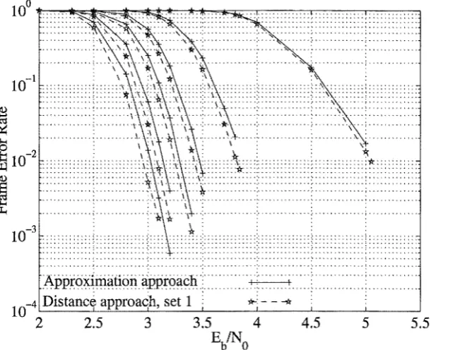
![Figure 3.32: Results for the (64, 51, 6) 2 block Turbo code using the approximation approach, distance approach (set 1) and the precomputed approach of [90] are shown](https://thumb-us.123doks.com/thumbv2/123dok_us/9041060.400425/90.595.136.457.361.614/figure-results-approximation-approach-distance-approach-precomputed-approach.webp)