APPLICATIONS OF NONLINEAR OPTICS TO THE
DEVELOPMENT OF ALL-SOLID-STATE SOURCES OF
TUNABLE LIGHT.
Yan Tang
A Thesis Submitted for the Degree of PhD
at the
University of St Andrews
1997
Full metadata for this item is available in
St Andrews Research Repository
at:
http://research-repository.st-andrews.ac.uk/
Please use this identifier to cite or link to this item:
http://hdl.handle.net/10023/14949
Ha
University of St Andrews
School of Physics and Astronomy
St Andrews, Fife
KY16 9SS
Applications of Nonlinear Optics
to the Development of All-Solid-State
Sources of Tunable Light
A thesis presented to the University of St Andrews
in application for the degree of Doctor of Philosophy.
by
Yan Tang
(School of Physics and Astronomy)
ProQuest Number: 10166478
All rights reserved
INFORMATION TO ALL USERS
The quality of this reproduction is d e p e n d e n t u p on the quality of the co p y subm itted.
In the unlikely e v e n t that the author did not send a c o m p le te m anuscript
and there are missing p a g e s , these will be n o ted . Also, if m aterial had to be rem o v ed , a n o te will in d icate the d eletio n .
uest
ProQ uest 10166478
Published by ProQuest LLO (2017). C opyright of the Dissertation is held by the Author.
All rights reserved.
This work is protected a g a in st unauthorized copying under Title 17, United States C o d e Microform Edition © ProQuest LLO.
ProQuest LLO.
789 East Eisenhower Parkway P.Q. Box 1346
D ecla ra tio n
I, Yan Tang, hereby certify th a t this thesis, which is approxim ately 50000 words in length, has been w ritten by me, th a t it is the record of work carried out by me and th a t has not been subm itted in any previous application for a higher degree.
date signature of candidate ...
I was adm itted as a research student in November, 1993 and as a candidate for the degree of Doctor of Philosophy in April, 1997; the higher study for which this is a record was carried out in the University of St. Andrews between 1993 and 1997.
date signature of candidate
I hereby certify th a t the candidate has fulfilled the conditions of the Resolution and Regu lations appropriate for the degree of D octor of Philosophy in the University of St. Andrews and th at the candidate is qualified to subm it this thesis in application for th a t degree.
Ill subm itting this thesis to the University of St. Andrews I understand th a t I am giving permission for it to be m ade available for use in accordance w ith the regulations ol the University Library for the tim e being in force, subject to any copyright vested in th e work not being affected thereby. I also understand th a t the title and ab stract will be published, and th a t a copy of the work m ay be m ade and supplied to any bona fide library or research worker.
A ck n o w led g em en ts
First and forem ost I would like to thank my research supervisor, Professor Malcolm Dunn, for his guidance, encouragem ent and invaluable advice during the period of this work. I would also like to thank my joint supervisor, Professor W ilson S ibbett, for kindly help in m any aspects. I also wish to acknowledge the Women Centenary Fellowship C om m ittee for awarding me the research fellowship and all the financial support during my three year’s study.
This is an opportunity to say especial thanks to my colleague Cam eron Rae for his generous help, discussion and support through all of my work and patience in correcting all my English writing. I am also grateful to C hristian Rahlff for the early collaboration on the construction of the slab geom etry laser. I also wish to express my thanks to Finlay Colville, for m any helpful discussions regarding the OPO theory and for one very useful suggestion from him in building a folded cavity to detect the idler wave of the K T P OPO. My thanks also should go to my colleagues, G arry M orrison and Dominic W ithers for their kindly help whenever I need a hand in my work. In this opportunity, I also wish to thank Jian W ang for helpful discussion in the late stage of my work and the help to enable me to use lATjrXto write my thesis.
P u b lica tio n s and P a p ers
“L ow th re s h o ld , h ig h efficien cy a n d w id e ly tu n a b le in fra re d s o u rc e fro m a K T P b a se d O P O ” , Yan Tang, Cam eron F. Rae, C hristian Rahlff and Malcolm H. Dunn, (paper has been subm itted to J. Opt. Soc. Am . B, in M arch 1997).
“T u n in g , th re s h o ld a n d c o n v e rsio n efficien cy p r o p e rtie s o f c ritic a lly p h a se - m a tc h e d K T P O P O s ” , Y. Tang, C. F. Rae and M. H. Dunn, in Conference on Lasers and Electro-Optics (Anaheim , California, 1996), OSA Technical Digest Series., Paper CW F14, 266 (1996).
“H ig h r e p e titio n - r a te , m id -in fra re d K T A -O P O a t 3.44 p/mT, C. Rahlff, Y. Tang, W. Sibbett and M. H. Dunn, in Conference on Lasers and Electro-O ptics (Anaheim , California, 1996), OSA Technical Digest Series^ Paper CW F16, 267 (1996).
“ T h e r m a l d e p e n d e n c e o f th e p rin c ip a l re fra c tiv e in d ices o f lith iu m t r i b o r a t e ” , Y. Tang, Y. Cui, and M. H. Dunn, J. Opt. Soc. Am . B, 1 2, 638-643 (1995).
“ L o w -th re s h o ld o p e r a tio n o f a n a ll-s o lid -s ta te K T P o p tic a l p a r a m e tr ic o scilla t o r ” , J. A. C. Terry, Y. Cui, Y. Tang, W. Sibbett and M. H. D unn, J. Opt. Soc. Am .
B, 11, 758-769 (1994).
“ C o m p a ris o n o f lith iu m t r ib o r a te a n d b e ta b a riu m b o r a te as n o n lin e a r m e d ia fo r o p tic a l p a r a m e tric o s c illa to rs ” , M. H. Dunn, Y. Cui, A. J. Henderson, G. R ober son, Y. Tang, D. E. W ithers, W . Sibbett, and B. D. Sinclair J. Opt. Soc. Am . B 1 0, 1737-1743 (1993).
“W id e ly tu n a b le o f a ll-s o lid -s ta te o p tic a l p a r a m e tric o s c illa to r fo r t h e v isib le a n d n e a r in f r a r e d ” , Y. Cui, D. E. W ithers, C. F. Rae, C. J. Norrie, Y. Tang, B. D. Sinclair, W. Sibbett, and M. II. Dunn, Opt. Lett. 18, 122 (1993).
“ A ll-s o lid -s ta te o p tic a l p a r a m e tr ic o s c illa to r fo r th e v is ib le ” , Y. Cui, M. H. Dunn, C. J. Norrie, W . Sibbett, B. D. Sinclair, Y. Tang, and J. A. C. Terry, Opt. Lett.
“ A ll-s o lid -s ta te o p tic a l p a r a m e tr ic o s c illa to r fo r th e v is ib le ” , Y. Cui, M. H. Dunn, C. J. Norrie, W . Sibbett,, B. D. Sinclair, Y. Tang, and J. A. C. Terry, in Conference on Lasers and Electro-Optics (Anaheim , California, 1992), OSA T'eclinical Digest Series, 1 2, Paper C T uR l, 198 (1992).
“ A lith iu m t r ib o r a te o p tic a l p a r a m e tr ic o sc illa to r p u m p e d a t 266 n m ” , Y. Tang, Y. Cui, and M, H. Dunn, Opt. Lett. 17, 192 (1992).
A b stra ct
This thesis describes the development of singly-resonant optical param etric oscillators (O PO s) based on the nonlinear m aterial K T P (potassium titanyl phosphate), and used to provide tunable light in the infrared, w ith low oscillation threshold and high efficiency. Further, the generation of tunable red light by the frequency mixing of the signal wave from the OPO with the pum p wave in a non-critical tem perature phase-m atched lithium tribo rate crystal (LBO) is reported. We believe this is the first dem onstration of such an application of LBO.
Two diode-pum ped solid-state lasers were used as the pump sources. One was an electro- optically Q-switched Nd:YLF laser which provided high peak power (~600 kW ) pulses; and the other one was an acousto-optically Q-switched slab-geom etry Nd:YLF laser which provided high repetition rate (1~10 kHz) and low peak pow er(<30 kW ) pulses. A second version of the aeonsto-optic.ally Q-switched slab-geom etry NdtYLF laser was designed and constructed with im provem ents in the pum p module and cooling system so as to be much m ore com])act and easier to control.
In the first stage of this work, two theoretical models were constructed. One was a model for pump threshold of singly-resonant OPOs for the case of focused Ganssian beam s, and was based on G uha’s theory. The second one was a model for conversion efficiency of singly-resonant O PO s, for the case of plane waves witli pum p depletion, and was derived from the coupled wave equations.
the double-jiass-piuTip configuration. M aximum external conversion efficiency from pum p to signal was dem onstrated to be 37% for the NCPM OPO and 40% for the CPM OPO. The signal wavelength tuning ranges were observed to be 1.54-1.56 p.m from the NCPM K TP O PO , and 1.58-1.8 //-m from the CPM K TP OPO.
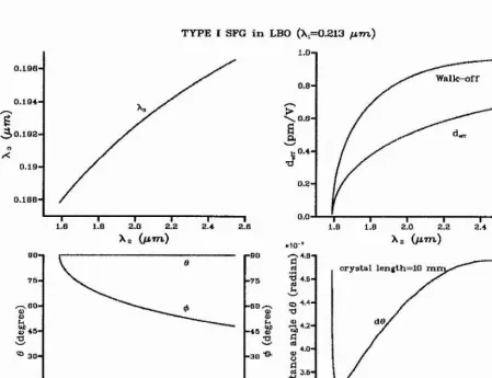
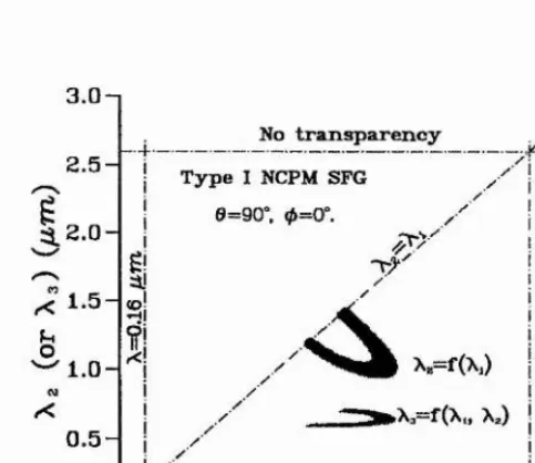
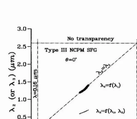
In the final stage of this work, the tem perature phase-m atching proi)erties of LBO were investigated with the use of our m easured therm o-optical coefficients of LBO. A particu larly interesting result of the investigation is the possibility of sum -frequency generation in non-critically phase-m atched LBO w ith tem perature tuning giving considerable wave length ranges for both th e type I and type II geometries. Experim entally, we dem onstrated
C on ten ts
D e c la ra tio n ... 2
A cknow ledgem ents... 4
Publications and P a p e r s ... 5
A b s tr a c t... 7
1 In tro d u ctio n 13 j t 1 1.1 All-solid-state tunable optical param etric o s c illa to r... 14
1.2 Tunable lights in i n f r a r e d 15
1
1.3 Fiequency up-conversion from OPO 18 iI
1.4 This w o r k 20 | 1.5 Thesis o u tlin e ... 202 T h eo retica l B ack grou nd 25 2.1 The second-order nonlinear in te ra c tio n ...25
2.1.1 Nonlinear susceptibility and the d-effective coefficient ...29
2.1.2 Optics of crystals and double r e f r a c tio n ... 32
2.2 Wave equations for propagation in nonlinear media... 36
2.2.1 The coupled wave equations for plane w a v es... 36
2.2.2 Nonlinear optical interactions with focused Gaussian b e a m s ... 44
2.3 Phase-m atching and acceptance ])a .ia m e te rs...46
2.3.1 Angle p h a s e -m a tc h in g ... 47
2.3.2 Tem perature p h a s e -m a tc h in g ... 48
2.3.3 Acceptance param eters ...48
2.4 Theory of singly-resonant O P O ...50
2.4.1 Gain and pum p th r e s h o ld ...50
2.4.2 Conversion efficiency ... 59
2.4.3 OPO lin e w id th ...62
2.5 Theory of sum-frequency g e n e r a tio n ...63
2.5.1 Optim um f o c u s in g ... 63
2.5.2 Conversion efficiency...64
3 N o n lin ea r m aterial 68 3.1 A review on some useful c r y s t a l s ...68
3.1.1 Lithium niobate (LiNbOa) and Lithium iodate (L ilO s )...68
3.1.2 Potassium niobate (K N bO s) ... 73
3.1.3 Betabarium borate (B B O )... 74
3.2 Potassium titanyl phosphate and its is o m o rp h s ... 75
3.2.1 K T P ... 75
3.2.2 Isom orphs of K T P ... 79
3.3 Lithium trib orate (L B O )...84
4 P u m p sou rce 95 4.1 The eiectro-optically (EO ) Q-switched Nd:YLF l a s e r ... 96
4.2 The acousto-optically (AO) Q-switched Nd:YLF laser ...98
4.2.1 Pum p optics and pum p module d e s ig n ...100
4.2.2 Cooling system im p ro v e m e n t...101
4.2.3 Laser c a v ity ...103
4.2.4 O perational p ro p e rtie s ...103
5 K T P O P O 105 5.1 Design considerations ... 106
5.1.1 C rystal design ... 106
5.1.2 Beam f o c u s in g ... 110
5.2 Single-pass-pnmped O P O ... 114
5.2.1 Oscillation tlire s lio ld ... 110
5.2.2 Conversion efficien cy ... 118
5.2.3 W avelength t u n i n g ... • 121
5.2.4 Transverse m o d e ... 123
5.3 Double-pass-pum ped O P O ... 124
5.3.1 Oscillation th re s h o ld ... 124
5.3.2 Conversion efficiency...127
5.3.3 W avelength t u n i n g ...131
5.3.4 Transverse m o d e ...132
5.3.5 OPO line width m easu rem en t... 132
5.4 Cylindrical focusing pum p c o n fig u ra tio n ...133
5.5 Intracavity K TP O P O ...134
5.6 Idler wave detection ...136
6 T h erm o -o p tica l coefficien ts o f LBO 139 6.1 E x p e r im e n t...139
6.2 D etennination of d n / d T ... 142
6.3 A s s e s s m e n t... 146
6.4 Tem perature phase-m atching properties of L B O ... 150
7 T un ab le red light g en era tio n 157 7.1 The type I NCPM LBO c r y s ta l ...158
7.2 Tem perature control and crystal holder ... 158
7.3 Beam focusing and conversion e ffic ie n c y ... 159
7.4 E x p e r im e n t...162
7.4.1 The first c o n fig u ra tio n ...162
7.4.2 The second configuration ... 164
7.4.3 The third c o n fig u ra tio n ...165
7.5 Phase-m atching tem perature and the wavelength t u n i n g ...166
7.6 Conclusion ... 167
8 C on clu sion s 169
C h ap ter 1
In trod u ction
In recent years, the great progress in diode-pum ped solid-state lasers and nonlinear m ate rials has opened up opportunities for exciting developments of nonlinear optical frequency conversion. Highly efficient, reliable, com pact, and long-lived coherent radiation sources with flexible frecpiency choice are not only seen in the laboratory but also in the com mercial m arketplace. The spectral range covered by developed nonlinear optical devices now can be throughout the ultraviolet to the far-infrared. Even so, there is still a great deal of room left for the study and development of nonlinear optical frequency conversion techniques. For example, we know th a t as one of the m ost useful m aterials in the infrared, K TP has been used for non-critically phase-m atched (N C PM ) O PO s pum ped at i p m ,
and has received a great deal of attention because it is able to operate with a low power laser ])ump and at high efficiency at the useful eye-safe signal o u tpu t wavelength of 1.5 pm .
However, it cannot be wavelength-tuned effectively. An interesting question then comes up, namely can a critical phase-m atched (C PM ) K TP OPO operate at low power pum p with reasonably high efficiency? This would be irn]>ortant for im proving the availability of practical tunable sources in the infra,red region. In addition, as we know, it is also difficult to get tunable radiation in the ultra,violet. Currently, LBO is the only crystal which is phase-m atchable down to 0.16 p m and has potential for tem pera,ture tuning over the uv region. However, until recently, tem perature-tuned LBO has been m ostly used for OPOs pum ped in the near ultraviolet or green [1, 2], and not much attention has been paid to sum-frequency generation for extending tuning ranges to shorter wavelengths.
Based on the study of nonlinear optical frequency conversion, this thesis describes the development, of singly-resonant, K TP OPOs and fre([uency up-conversion from sucli OPOs using sum-fre(piency mixing of their o utputs with that, of the pum p laser in non-critically
CH APTER 1. INTRODUCTION 14
phase-m atched LBO. The principal goal of this work is to investigate th e feasilhlity of low threshold, high efficiency operation of an OPO using only m odest pum p energies available from diode-pum ped Q-switched Nd:YLF lasers, and the feasibility of im proving spectral coverage in the infrared and uv regions. In order to develop all-solid-state tunable sources, all the nonlinear frecpiency conversion devices developed in this work were based on the use of diode-pum ped Nd:YLF lasers.
1.1 A ll-so lid -sta te tu n ab le op tical param etric oscillator
Right from the first dem onstration of the laser, an im portant goal has been the develop m ent of widely-tun able devices covering m any sjiectral regions.
In early times, dye lasers and color center lasers were the only available sources for gener ating tunable light. The range of the spectrum covered by dye lasers using different dyes can be 0.4-1 pm; and it can lie 0.8-4 p m from color center lasers. However both ty])es of lasers are inconvenient to use either because fresh dye solution m ust be constantly flowed through the active region for a. dye laser, or because of the cryogenic tem perature needed for operation for a color center laser.
Vibronic crystal lasers were a more recent and exciting developm ent, as convenient and now widely-used tunable sources. However, the tuning range with each crystal is limited to a. small range.
In contrast witli the above, the optical param etric oscillator is the m ost convenient source to use, since it can convert laser light at one frequency to a broad frequency range, while preserving the general characteristics of the initial input wave.
CH APTER 1. INTRODUCTION 15
linewidth and iriuch im proved spatial m ode quality. These two significant advances are opening the door for a new generation of com pact, reliable and widely tunable sources, which are nam ed: all-solid-state tunable sources. A typically exam ple of such a device is illustrated in Fig. 1.1. Basically the system includes a diode-pum ped solid-state laser [often, it is a neodym ium (Nd) laser.], an optional frequency up-converter, and an optical param etric oscillator. It can be seen th a t all the radiation generation processes in an all-solid-state tunable source are carried out entirely within the solid-state phases.
F1 F2
OPO
Diode pum ped
solid-state laser
{}
up-convertorFrequencyr(H
Tunable light output
Figure 1.1: Configuration of an all-solid-state tunable source.
1.2 Tunable lights in infrared
T he development of tunable radiation sources has long been of interest in the infrared region. The presence of m any molecular vibrational lines makes th a t region attractiv e for spectroscopy, with uses from basic research to petroleum exploration. Strong w ater lines are promising for medical treatm ent and for applications such as sensing w ater content in integra.ted-circuit packages. M ilitary agencies are also looking at this spectral region for laser counterm easures against sensors. Because of eye safety, infrared radiation is attractive for applications such as laser radar, rem ote sensing, and range-finding.
However, the lack of good tunable laser sources in this region has hindered development of these applications. Lead-salt and color-center lasers are tunable, but their inherent lim itations have restricted their use. Free-electron lasers and chemical lasers are much more powerful but have their own operation restrictions. In contrast, O PO s with the possibili ties of broader tunability over much of this region and generating millijoule, nanosecond pulses in a. m ore m anageable package are prom ising to replace the above infrared lasers for these applications.
CHAPTER 1. INTRODUCTION 16
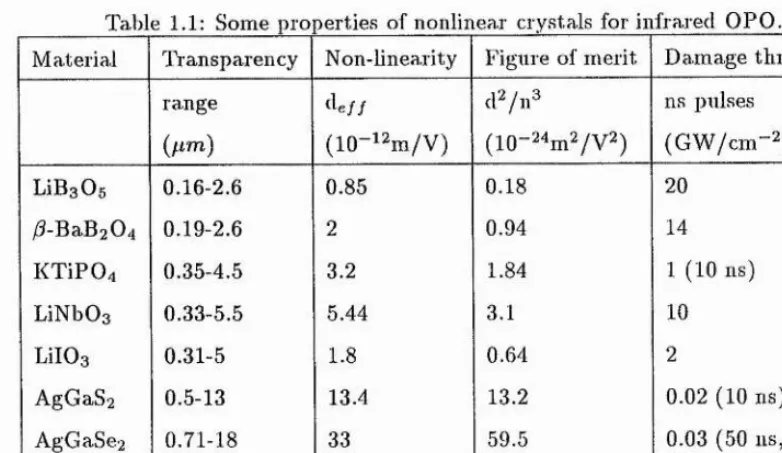
Table 1.1: Some properties of nonlinear crystals for infrared OPO M aterial Transparency Non-linea.rity Figure of m erit Dam age threshold
range dfi// d^/n^ ns pulses
{pm ) (10- i2m /V ) (10- ^ W / v ^ ) (G W /c m -2)
LiBgOs 0.16-2.6 0.85 0.18 20
/3-BaB2 0^j 0.19-2.6 2 0.94 14
K T iP 04 0.35-4.5 3.2 1.84 1 (10 ns)
LiNbOg 0.33-5.5 5.44 3.1 10
LilOg 0.31-5 1.8 0.64 2
AgGaS2 0.5-13 13.4 13.2 0.02 (10 ns)
AgGaSe2 0.71-18 33 59.5 0.03 (50 ns, 2 m m )
ZnGePg 0.74-12 88 247.8 0,05 (25 ns, 2 mm)
in Table 1.1. The choice of crystal depends on operating conditions, available pum p source wavelength and i)ump energy level.
In early tim es, the work was concentrated on the use of m aterials such a.s LiNbOa and LilOg. However, these m aterials suffered m any problems, in particular, the problem of low dam age threshold, which limited the infrared OPOs from operating at high power and high efficiency.
The large nonlinear coefficients and extended infrared transpai ency ranges m ake chalcopy- rite crystals an im portant class for infrared param etric devices. B ut the useful crystals in this family, Z nG ep2, AgGaS^, and AgGaSe2, suffer from low o]>tical dam age intensities. An interesting possibility is the feasibility of tuning the entire range from 2.3 to 18 p m
using a single AgGaSe2 crystal pum ped by a. Ho:YAG laser at 2.05 p,m.
Since the last decade, the newly developed m aterials: BBO, LBO, K T P and its isom orphs, with their several attractiv e properties of large high dam age threshold and wide transparency range, have given great promises for high efficiency param etric applications in the spectral regions of infrared.
[image:19.613.100.491.60.286.2]CH APTER 1. INTRODUCTION 17
The LBO based OPOs in the infrared region also are im portant. The high dam age thresh old and lower liirefringence of LBO have m ade it an interesting m aterial for uv pum ped broadly tunable OPOs using only m odest energies from diode-pum ped solid-state lasers and tight focusing. M oreover, LBO allows for tem perature tuning over its entire tuning range under non-critical phase-m atching conditions. For exam ple, as reported by Lin et a i [6], with the use of LBO and pum p at 0.532 p m , the wavelength can be tuned over a broad spectral range from 0.65 p m to 2.5 p m in a type I NCPM tem peratu re tuning geometry.
For infrared O PO , pum p wavelength is an im portant consideration. Principally, with the use of suitable nonlinear ma.terial and the 1 //.m pum p light from th e prim ary pum p laser, tunable radiation in infrared spectral region can be produced effectively in only a single- step process. Pum p wavelength is also im portant ])articularly when it is recognised th at ])hase-raa.tching and oscillation become more difficult as the difference between signal and idler beams increases. Thus 1p m neodym ium lasers work much b etter as pum ps for OPOs em itting 2 to 3 /rm radiation than for generating longer signal wavelengths.
K TP can be phase-m atched at 1p.m, and m eets m any key l equirem ents for high efficiency param etric devices as seen in the Table 1.1. Previous works have shown th a t the NCPM K T P OPO can be operated at a low pum p ])ower with high efficiency. For instance, M arshall et al. have reported for 47% external conversion efficiency from pum p to signal in a singly-resonant device[7]; and Terry el al. reported a low pum p threshold of around 0.5 rnJ [8]. The disadvantage, of this OPO is the slow wavelength tuning rate. As the phase-m atching angle of K T P is turned away from the NCPM point (6^=90^'), the phase- m atching becomes a critical geom etry, and the wavelength tuning ra te in such a geom etry increases sharply. The entire wavelength tuning range for a 1p m pum ped K T P OPO is 1.5-3.3 p m , which covers the greater p art of the m id-infrared region. Until now, although the wide tuning range in the infrared spectral region is so im p o rtan t, the 1 p m pum ped K T P OPO in a CPM geom etry has only been m entioned in a few publications [9, 10] with no investigation of efficiency and pum p threshold. We believe this is because of the walk-off problem in the CPM geometry. In fact, it is notable th a t there are two attractive features in the CPM K T P OPO when the crystal is oriented on either the x - z ])lane
CHAPTER, 1. INTRODUCTION 18
A lternative m aterials to K T P are its isom orphs, e.g. KTA, ETA, and CTA. These are relatively new crystals and have very sim ilar wavelength tuning properties to that, of the K T P but with much broader transparency ranges of 0.35 - 5.3 pm . Therefore th e study of a K T P based OPO is also useful for the further work with the use of its isom orphs for
OPOs to extend the tuning range to 4 ~ 5 p m .
A nother notable advance recently in the field of infrared OPOs is the use of periodically poled lithium niobate (PPLN ) for quasi-phase-m atching (Q PM ). QPM was proposed be fore birefringence phase-m atching]! 1], but difficulties in fabrication QPM m aterials have prevented its application. Recent advances in fabricating practical QPM m aterials have renewed interest in this approach. PPLN has very large effective nonlinearity {(Cfj),
and with suitalde period it can provide non-critical phase-m atching for generation of any wavelengths in its transm ission range from 0.35 - 4 p.m. The main disadvantage of PPLN currently is its small aperture due to the lim itation of fabrication. This has restricted the a])plications in low power pum p case, such as f s lasers and cw lasers pum ped OPOs. The first PPLN synchronously pum ped OPO has been dem onstrated by B utterw orth et al. [12]. In this experim ent, a frequency-doubled diode-pum ped APM Nd;YLF laser was used as the pum p, the OPO can l)e tem perature tuned over the ra.nge of 0.9 -1.3 p/in. Also as reported in C LEO ’96, the first 1 p m pum ped cw singly-resonant OPO based on PPLN has been dem onstrated by Bosenberg et al. [13], the pum p threshold in this device can be as low as a. few w atts, and more than 1 w att of radiation with a broad tuning range in the m id-infrared was produced. Although PPLN is not suitable for Q-switched laser pum ped OPOs because of the unavailability of large apertures and therefore increased risk of dam age, Myers et al. have reported the use of a diode-puni])ed Q-switched Nd:YAG laser to pum p the PPLN based OPO . They achieved 0.1 m.l of pum p threshold, which was more than a factor of 10 below the dam age lim it.
1.3 Frequency up-conversion from O PO
CH APTER 1. INTRODUCTION 19
An alternative approacli can be optical param etric oscillation followed by sum-frequency generation of the signal and residual pum p, e.g. OPO-f-SFG. In the second approach, if the frequency mixing is between the signal wave and harm onic wave of the pum p, this geom etry means th a t the pum p m ust be separated into two p arts before th e O PO , one p art for the O PO , and other one for the harm onic generation.
The advantage of the first approach is th a t it is m ore direct than the second approach to achieve tunable radiation at short wavelength. The BBO, LBO or green pum ped K TP OPO s are all examples of this approach. The shortest tuning ranges th a t can be reached by this approach currently are lim ited to the near ultraviolet region.
Ill contrast, there are two m ajor advantages in the second approach. F irst, the possibility of extending the tunable range to the deep uv. Second, less steps of frequency liarm onic generation may be required beca.use the final stage of frequency up-conversion can bring the generated wavelength further towards short wavelengths. The theoretical and exper im ental investigation of sum-frequency generation between the pum p and the signal in intracavity geometries were investigated ju st shortly after the advent of the optical pa,ra- m etric oscillator [14, 15]. Now, the newly developed crystals, such as BBO and LBO have opened the door for the use of the second approach in freipiency up-conversion. As we know, the shortest output wavelength of BBO is limited by its cut-off wavelength in the uv region and its large birefringence also effects the outqiut beam qua.lity and conversion process, so th at the m ost favourable ma.terial in this application is LBO. R.ecently, sev eral results on the use of the second approach with LBO to generate radiation in uv and visible have been reported [16, 17, 18, 19, 20]. Among them , there are two interesting achievements. F irst, the high efficiency uv generation at 0.289 p m has been dem onstrated by M arshall et al. [16]. They obtained 0.5 W uv output at 289 nm from a 2 W (80 Hz) 1.064 pan diode-pum ped laser by frequency mixing of one wave of 0.355 p m and one wave of 1.58-1.59 p m from a K T P O PO , the overall efficiency from the pum p laser to the uv was 25%. The second is where the generated tunable wavelength has reached as short as 172.7 nm as reported by Seifert et al. [17]. In their work, the tunable o u tp u t (0.74 -0.85 fim) from a. fs Ti:sapphire regenerative amplifier system was split into two equal parts for generating of fourth harm onic and tunable infrared radiation a,round 1.9 p m in a tem perature tuned LBO O PO , and then the two waves were combined in LBO cut at
CHAPTER 1. INTRODUCTION 20
uv light generation in the range of 188-242 nm from a pulsed Nd:YAG laser.
So far, there lias no report of the use of tem perature tuned LBO in SFG , despite the fact th at the tem perature tuning offers much more favourable advantages than angle tu n ing. This might be due to the lack of accurate therm al-optical coefficient for prediction. Therefore, we believe, the work presented in this thesis regarding the m easured therm al- optical coefficients of LBO would be very useful for improving this situation and extending applications of LBO in such areas.
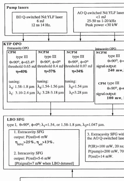
1.4 T his work
The program m e of this work is outlined in Fig. 1.2. The work were carried out in four steps, which are; (1) C onstruct a cw diode laser pum ped Q-switched NdiYLF laser; (2) De velop a 1.047 fim pum ped K T P for both NCPM and CPM geometries; (3) Experim entally m easure therm o-optical coefficients for LBO; (4) G enerate tunable red light (0.62-0.65
p m ) by freipiency mixing th e signal beam of the K T P OPO and the pum p beam in a non-critical tem perature phase-m atched LBO.
A EO Q-switched diode-pum ped NdrYLF laser was used for the initial experim ental study, because of its higher peak power than the th a t of the AO Q-switched Nd;YLF laser.
1.5 T h esis ou tlin e
CH APTER I. INTRODUCTION 21
Pump lasers
EO Q-switched NdiYLF laser
6 mJ
12 ns 14 Hz.
AO Q-switched NdiYLF laser
<1 mJ
25-50 ns 1-20 kHz
Peak power <30 kW
KTP OPO
Extracavity OPO Intracavitv OPO
CPM NCPM NCPM NCPM
type
III
typeIII
typeIII
typeIII
0=900, ({,=63.40
8=900, ({>=00
8=900, (|)=oo
8=90^, (j)=0^^
threshold0.65 ml
threshold0.4 mJ
threshold0.07 mJ
signal output11=40%
11=37%
11=34%
240 mw,1.9
kHz
tuning: tuning: tuning: CPM type
III
X^:
1.58-1.8 pm Ag: 1.54-1.56 pm
Ag=1.54 pm
8=900, (|)=63.40
A-j! 3.10-2.4 pm Ap 3.28-3.18 pm
Ap3.28 pm
signal output100 mw,
1.1 kHz
LBO SFG
type I, 6=90^, (|)=0°; Aj=1.54, or 1.58-1.8 pm,
1.047 pm.
1. Extracavity SFG
3. Extracavity SFG with
output: P(red)=6 mW
the AO Q-switched laser:
P(IR)=100 mW, 20 ns;
2. Intracavity SFG
P(pump)=200 mW, 70 ns;
output: P(red)=5-6 mW
P(red)=14 mW.
[P(signal)=7 mW when LBO detuned]
T herm al-optical coefficients of LBO m easurem ent
(20 OC < T < 200 OC)
[image:24.614.83.507.67.684.2]CHAPTER 1. INTRODUCTION 22
B ib liograp h y
[1] Y. Tang, Y. Cui, and M. H. D unn, Opt. Lett. 17, 192 (1992).
[2] G. R obertson, A. Henderson, and M. H. Dunn, Opt. Lett. 16, 1584 (1991).
[3] C. C. W ang and G. W . R acette, Appl. Phys. Lett. 6, 169 (165).
[4] .1. A. Giordam aine and R. C. Miller, Phys. Rev. Lett. 14, 973 (1965).
[5] W. R. Bosenberg and C. L. Tang, Appl. Phys. Lett. 56, 1819 (1990).
[6] S. Lin, J. Y. Huang, J. Ling, C. Chen, and Y. R. Shen, Appl. Phys. Lett. 59, 2805- 2807 (1991).
[7] Alex Kaz, Larry R. M arshall, C W D l, C LEO ’93.
[8] J. A. C. Terry, Y. Cui, Y. Tang, W. Sibbett, and M. H. Dunn, J. Ojd. Soc. Am. B
11, 758 (1994).
[9] K. K ato, IE E E J. Qvantuvi Electron. QE-27, 1137 (1991).
10] J. T. Lin, Optical and Quantum Electronics 2 2, S283 (1990).
11] J. A. A rm strong, N. Bloembergen, J. Ducuing, and P. S. Pershan, Phys. Rev. 127, 1918 (1962).
12] V. Pruneri, S. D. B utterw orth, D. H anna, Appl. Phys. Lett. 69, 1029-1031, (1996).
13] W. R. Bosenberg, et al., CTliA3, C LEO ’96.
14] P. P. BEY, and C. L. Tang, IE E E J. Quantum Electron. QE-8, 361 (1972).
15] A. J. Campillo, IE E E J. Quantum Electi-on. QE-8, 914 (1972).
16] L. M arshall, Laser Focus World 83-87, April (1994).
BIBLIOG RAPH Y 24
[17] F. Seifert, J. Elngling, F. Noack, V. Petrov, and 0 . Kittelma.nii, Opt. Lett. 19, 1538-1540 (1994).
[18] A. Borsutzky, R. Brlinger, and R. W allenstein, Appl. Phys. B 5 2 , 380-384 (1991).
[19] E. C. Cheung, Karl Koch, and Gerald T. M oore, Opt. Lett. 19, 1967 (1994).
C h ap ter 2
T h eoretical B ackground
III this chapter, the general physical principles responsible for the second-order nonlin ear optical frequency conversion process are described, and equations are derived for suni-freqiiency mixing and optical pa.rametric generation processes. Additionally, in this chapter, detailed consideration is given for the design of singly-resonant OPOs, and fre quency up-c.onversion devices, including optim um phase-m atching, conversion efficiency, and threshold calculations. MKS units are adopted throughout the analysis.
2.1 T h e second-order nonlinear interaction
W hen an electrom agnetic wave E , projiagates through a dielectric m aterial, it induces a polarization P . In the case where the electric field is smaller th an the intra,-atom ic field, the response of the induced polarization will be linear, and is descrilied by the constitutive relation
= (2.1)
where Ec> is the free space perm ittivity and is the linear susceptibility. The real p art
of the linear susceptibility is related to the refractive index of the m edium , n, by and is responsible for the fam iliar linear optical phenom ena of reflection and refraction. In the case of where the electric field strength is com jiarable to the intra-atom ic electric held, as with laser radiation, this linear relation between induced polarization and field no longer suffices, and Eq.(2.1) is replaced by a power series in the field namely:
P = + .... (2.2)
CHAPTER 2. THEORETICAL BACKGROUND 26
where are the nonlinear susceptibilities of the m edium respectively and are tensors of the third, fourth, and higher ranks. It m ust be noted th a t although So
is separated from following the procedure in linear optics, this is traditionally not extended to th e higher order susceptibilities[l]. Concern here is w ith the first nonlinear term only. This is usually referred to as the second order nonlinear susceptibility. This term is only finite in anisotropic m edia, and in order to describe such m edia the relationship is rew ritten in term s of the polarization vector
p(2) ^(2).e e (2.3)
Consider the circum stance in which the nonlinear polarization is produced by the interac tion of two waves at the frequencies u i and W2, where^
E i{z, t) = E l cos{kiz + üJit)
and
E-ziz, I.) - Ez cos{kzz + uJzt)
Substituting the superposition of these two waves for E , and assum ing th a t P and E are along the same direction z, then we expect the nonlinear polarization to be of the form
/>{2) — ^(2)j-^2 (.,0S^(A':iZ -f bJii) P E l CO^'^{kzZ + iVz't)
P2E1E2 cos(Aqz P u)it) cos(A:2^ + W2/)]
The polarization then consists of a num ber of com ponents with different frequencies; th a t
T n general, these two waves do have different phases and, strictly, they should be written as follows:
CHAPTER 2. THEORETICAL BACKGROUND 27
fzw. = cos [2( t , z + « ,i) l (57*6’) (2.4) f 2w: = cos [2(k2Z + W2i)l {S H G ) (2.5) fw,+w: = x ‘^ > £ i£2Cos[(u., +W2)#. + {k, + k2)z)] {S F G ) (2.6) = x (^ 'E if:2Cos[(wi -W2)( + ( t , -A ;)^ )] {D F G } (2.7)
and a steady term ,
Po = %<")(Ef + £ |) (OP.) (2.8)
Here each expression has lieen labelled by the nam e of the physical process th a t it describes, such as second-harm onic generation (SHG), sum-frequency generation (SFG ), differ en ce- frequency generation (D FG ), and optical rectification (OR.). Considering the general case for SHG, th at is the two waves are derived from one fundam ental lieam, and so Ei = Ez., k i —kz, and wi=W2, then equations (2.4) and (2.5) can be combined and rew ritten as
P2w = P2wi + Pzw2
= cos [2{kz 4- wf)] (2.9)
Therefore, tlie process of SHG is in fact a special case of SFG and ca.n be described by Eq.(2.6). The processes of sum-frequency generation and difference-frequency generation are illustrated in Fig. 2.1 and Fig. 2.2 resjiectively. One interesting application of sum- frequency generation is to produce tunable radiation in the visible and ultraviolet spectral region l>y choosing one of the input waves to be a fixed frequency, and the other to be frecpiency tunable.
One im portant difference between the two processes of SFG and DFG can be deduced from the descrijrtion of difference-frequency generation in term s of a photon energy-level
^ Also the convention (see R ef.[l], P. 3) that the real field is given by
another common convention has been used, althongh, (see Ref.[2], P.7) is to define the real field as
E n = ( j E ? f . ' ( + ^.^ -.(fcz+ u.0)
T his results in the expressions for the nonlinear polarization com ponent differing by factor of 2 from Eqs. (2.4) -(2.7). T hat is;
CHAPTER 2. THEORETICAL BACKGROUND 28
(b)
(u)
Figure 2.1: Sum-frequency generation, (a) G eom etry of the interaction, (b) Energy-level description.
(b) (a)
3 ^
Û.X,
Figure 2.2: Difference-frequency generation, (a) G eom etry of the interaction, (b) Energy- level description.
diagram [pa.rt(b) of Fig. 2.2]. The conservation of energy requires th a t for every photon th a t is created at the difference-frequency cui, an input photon at the higher frequency 0*3 m ust be destroyed and a photon at the lower frequency ufz m ust be created. Thus, the lower-frequency input field is amplified by the process of DFG. For this reason, the process of difference-frequency generation is also known as optical param etric amplification (OFA).
If a nonlinear crystal used in a process of optical param etric am plification is placed inside an optical resonator, as shown in Fig. 2.3, the loz an d /o r w% fields, and if so desired the W3 = -f Cv>2 field can be m ade large through param etric amjilification and resonant processes. Such a device is known as an optical param etric oscillator.
M ,
pump laser ^m3 ^ N o n lin e a r m e d in in
ml m3 -'m2
CHAPTER 2. THEORETICAL BACKGROUND 29
2.1.1 N on lin ear su scep tib ility and th e ^/-effective coefficient
As previously m entioned, is a third-rank tensor with 27 com ponents in the form of 4-W2) when an interaction of the form , W3— coi+ujz is considered. The indices
i j k refer to the C artesian com ponents of the fields. In general, is dependent on the frequencies of all the fields involved in the nonlinear interaction. Under th e assum ptions of lossless m edia and negligible dispersion over the whole frequency range containing u*i, 0^2, and W3, a num ber of sym m etry conditions are introduced to restrict the various com ponents of and results in 27 essential, frequency independent com ponents [2]. After further reduction, can then be represented in the form
+ (^2) = fki (2.10)
where the relationships between the values of .7, k, and I. are given by
jA:: 11 22 33 23,32 31,13 12,21
1 : 1 2 3 4 5 G
The nonlinear susceptibility tensor is then re])resented by the 3 x 6 m atrix
^
d ll di2 di3 d \ 4 di5 di6^
^21 ^22 d.23 ^24 ^25 ^ 2 6 y ^31 f/3 2 ^33 (1,34 ^35 (I3 3 y(2 .11)
(2.12)
CHAPTER 2. THEORETICAL BACKGROUND 30
^ Vx{y>3)
^
Py(W3)
Pz(w3) y \
/
d ll di2 d\3 di4 di5 di3
d22 d.23 d.24 dzu dzs
dai ds2 d33 d34 dss dso
(2.13) ^%(wi)E^(w2)
i?y(a;i)i5y(u;2) ^z(W i)Eg(w2)
i?y(Wi)E^(w2) + Ez{oJl)Ey{uJ2) Ex{<^l)Ez{i^2) + E"_z(wi )E^;(W2) V Ex{i-Ol)Ey{UJ2) P Ey{U}l)Ej:{uJ2) j
However, strictly speaking, différence-frequency generation can only be described liy the same d{\ tensor under the condition of full perm utation sym m etry[2], i.e. the indices x.ijk
can be freely perm uted. For instance,
d l2 = %122 = X'2\2 =
d l4 = %123 = \'2i;3 = d25 (2 -1 4 )
Under this sym m etry condition, the independent elements of d,;/ reduce from 18 to 10, and the form of dji under this condition becomes
d =
^
dll di2 di3 di4 i/ifi did^
did d.22 d.23 d.24 di4 d\2y di5 d.24 ds3 d.23 di3 di4 j
(2.15)
^ P.r(Wl) ^ Fy(wi)
V Fz(wi) y) \ /
Hence, for difference-frequency generation, the process is described by
^ d ll di2 di3 di4 di5 did ^ did d22 (1-23 ^24 dl4 di2
e..(w z)e;(w2) ''
Ey{^^3)Ey{oJ2) Ez{0J3)E*{u)2)
Ey{i03)E*[uJ2) -f Ez{oJ3)Ey{u}2)
E^(w3)E;(W 2)-bEXw3)E*(w2)
Ex{^3)Ey{oJ2) p Ey{üJ3)E^{u}2) J
CHAPTER 2. THEORETICAL BACKGROUND 31
Using Eq.(2.13) to calculate the polarization, account has still to be taken of each po larization com ponent along the principal axes of the crystal in term s of E (w i), E(w2) and the nonlinear coefficient tensor. For convenience, an effective second-order nonlinear coefficient dgjj has been introduced for practical application by forming the lelationship
Pwi-f-u/2 = de//E (o ;i)E (w2) (2.17)
Boyd and Kleinman [3] have given the relationship between dg// and the nonlinear coef ficient tensor d,;(2w) as:
dgy; = U s • d (2w) : U1U2 (2.18) where U,; are the unit vectors denoting the direction of the polarization of the electric fields E,- within the crystal and at frequencies w,- ( / = 1,2 ,3 ). In order to obtain a direct expression of de/j from Eq.(2.18), the com ponents of unit vectors U ,(i = 1 ,2 ,3 ) need to be known first. If one takes k as the unit wa,ve vector, then the wave vector can be given by
K = n ( - ) k c (2.19)
where the directional orientation of k is described by resolving k onto the three principal axes through the relationships: k;,. = sin (A cos </), ky = sin (9 sin 0, and /?- = cos 6*; n is the refractive index in the propagation direction; 9 is the angle ]>etween the wave ])ropagation direction k and the z axis; and 0 is the angle from the x axis in the x — y plane. From M axwell’s equations, the com ponents of E now can be derived to be
Ei = ri2 'M 2? r(k . E) (2.20)
- K
where i = .r, 7/, z; , n,/, and 11^ are the principal refractive indices of crystal. The direction cosines of the electric field of a. m onochrom atic plane wave propagating in the direction k inside a nonlinear crystal can be w ritten as
k.
cos a
cos (I
COS 7 =
1.2 — tj.2
k.,. '«.2 — 77.2
-r,2
kx
r* 2 _ />>2
kz nt
k-r
11^ — iii
+
k.yf,2 — 'j,?2 7 ; k y "‘y k y , 2
+
4-iir — Hi
'/J2 #i 2 (2.21)
m2
CHAPTER 2. THEORETICAL BACKGROUND 32
ray). Therefore, the cosine vector of an electric field E(tj,:); propagating in a crystal with polarization I can be w ritten as:
U(w*)z : coso(tJi)/, C0 3P{ui)i, cos 7(0;,:)/. (2.22)
where I denotes a or b for the two eigen com ponents.
Finally, the m athem atical expression of dçjj in a very general form for a three wave interaction process can be w ritten as:
dg/y — U3 • d(cur + wg): U1U2
(2.23)
= t^3idic(üJi + W 2)(UiU2)(
where Usi is the ith com ponent of the unit vector U3, {i — x , y , z ) ; d,;((wi + 0*2) is the nonlinear coefficient tensor, (( = 1,2, ...f>.), and ( U iU2)( is the (th com ponent of a column vector.
It is im portant to note th a t we have adopted MKS units throughout the theoretical analysis and th at the d^jj coefficient is derived from the definition (2.3). Hence, the unit of dg/y are coulom.hs.voli~‘^. However there is an alternative convention, in which the nonlinear susceptibility is defined through the equation
p(2) = foX^'^bEE (2.24)
In this case the units of \d2) me tres vol.t~^{or p m / V ) . To convert from one convention to the other, the conversion factor used is
p m / V = 1 0 “ 'Y (3 () X 7t) • coulombjV^ (2.25)
2.1.2 O ptics of crystals and double refraction
(1 ) U n ia x ia l c ry s ta l: W ithin a uniaxial crystal a particular propagation direction exists called the optic axis or z axis, for which the observed liirefringence is zero. The birefrin gence is maximised if beam propagation is norm al to this direction. The plane containing the z axis and the wave vector k is nam ed the principal plane. A wave whose polarization is norm al to t he principal plane is called an ordinary wave, while light whose polarization is parallel to the principal plane is called an extraordinary wave. The refractive index of the o-wave does not depend on the. pro])agation direction, but the refractive index of the e-beam is a function of the polar angle 9, and can lie determ ined by the equation:
CHAPTER 2. THEORETICAL BACKGROUND 33
If 'U(, > Ilf then the crystal is term ed negative uniaxial; if < tie then it is positive un iaxial
(2) B ia x ia l c ry s ta l: In biaxial crystals, the dependence of refractive indices on the light ])ropagation direction and its polarization corresponds to a much m ore complex surface than for uniaxial crystals.
optic axis
X
Figure 2.4: Indications of refractive indices in biaxial crystal.
If we restrict the principal refractive indices to the order of < ‘iiy < Hz, and only
consider the case of light propagation in the principal planes x — z, x — y and y — z, then the optic a,xes, whose directions are given by the intersection points of the ellipse and circle in the index ellipsoid (see Fig. 2.4), will always be in the plane x — z. T he optic axis angle
V,, formed by one of the optic axes with the z a,xis can be found from the expression:
sin F- — — (, n't - n lVI2 //17it2
)l/2
(2.27)In the X — y plane, the refractive index of the wave polarized norm ally to this plane is constant and equals iiz, and th a t of the wave polarized in this plane cha,nges from 7iy to
U;,: with 0 varying from 0‘^' to 90". Hence, a biaxial crystal in the plane x — y is sim ilar to a negative uniaxial crystal with Hf, — 11^ and
ne(0) = 7/,y[(i + tan'^ 0 )/( 1 + {‘iiy/n^fŸ ta.n^(0)]^/'^ (2.28)
[image:36.612.192.392.172.383.2]CHAPTER 2. THEORETICAL BACKGROUND 34
Hz with 0 va.rying from 0® to 90^'. Hence, a biaxial crystal in the plane y — z is similar to a positive uniaxial crystal with tiq — and
(2.29)
Similarly in the x — z plane, it is th a t n„ = and
/ 2 (2.30)
However, at ^ it is similar to a positive uniaxial crystal, i.e. no < and at 6^ < Vg, it is sim ilar to a negative uniaxial crystal, i.e. Uo > ns{0).
(3) D o u b le re fra c tio n : In an anisotropic medium, the energy of an extraordinary wave propagates at an angle a from its wave pro])a,ga.tion direction k, where a is nam ed the double-refraction angle. The energy propagating direction vector s can be shown to be the norm al to the tangent drawn at the point of intersection of the wave vector k with the curve [5]. The relationship between vectors k and s for both negative and positive uniaxial crystals are shown in Figure 2.5.
(a) (b)
X (orY )
n,
He X (orY )
Figure 2.5: Displacement of the wave vector k and beam vector s in anisotropic negative (a) and positive (b) uniaxial crystals.
T he double-refraction angle in the case of uniaxial crystals is straight forw ard to derive as has been shown in Ref.[5] and is given by:
rv(6^) — ± arctan[('nf,/nf,,)^ • tan ^ 0
CHAPT'ER 2. THEORETICAL BACKGROUND 35
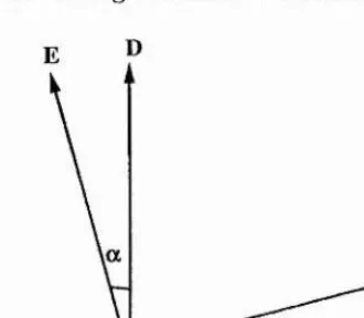
[image:38.613.210.375.193.337.2]For biaxial crystals, the calculation of the double-refraction angle is m ore com plicated. If we use D to represent the electric displacem ent and H to represent the m agnetic field, then M axwell’s equations imply th a t for a plane wave D , E and k are orthogonal to the m agnetic field H . Therefore D , E and k m ust be coplanar [4]. The Poynting vector S = E A H , means th a t the direction of the energy flow lies in the sam e plane as D , E and k, but is not parallel to k. Figure 2.6 shows the relative directions of these vectors, from which it can be seen th a t the angle between D and E is etpial to a. Hence we have
Figure 2.6: Relationship between the wave propagation direction k and the Poynting vector S, and between the electric field E and electric displacement vector D , in an anisotropic medium.
sin O' = e • k
and
cos a = e • d
where e and d are the unit vectors denoting the directions of E and D . As has been shown in R.ef.[6], with a few steps of derivation, the double-refractive angle for a biaxial crystal is given by
e • k 2 tan a = --- ~ n
e • d
+
k.
+
k. (2.31)For a three wave interaction, the walk-off angle is defined as the m axim um angle of Poynt ing vector walk-off associated with the three waves.
CHAPTER 2. THEORETICAL BACKGROUND 36
which is orthogonal to the polarization direction of the ordinary wave. From Eq.(2.31), it can be seen th at if two eigen-waves at frequencies and W2 have the same polarization direction, then the high frequency eigen-wave has a larger double-refraction angle a than the low frequency eigen-wave. Therefore, the walk-off angle is the double-refraction angle of the extraordinary eigen-wave with the highest frequency.
2.2 W ave equations for propagation in nonlinear m edia
The equations governing the propagation of electrom agnetic fields in a nonlinear medium are derived from M axwell’s wave equations describing a non-dielectric m edium condition, T h at is:
where 6 = 6u(l + e and //. are the electric and magnetic perm eabilities, and a is the coefficient of absorption. Assum ing th a t the Iiigiier-order term s than in Eq,(2.2) can be neglected, then Eq.(2.32) is the m ost general form of descri])tion for a wave pro])agating in a nonlinear medium with quadratic nonlinearity. The first term on the right hand side allows for absorption, while the other two are the source term s for wave proi)agation. Since an analytic solution for a Gaussian beam is im])ossible, the plane-wave approxim ation has been used all the tim e to analytically solve the wave equations.
2 .2 .1 T h e c o u p le d w a v e e q u a ti o n s f o r p la n e w a v e s
Considering a. total field E , m ade up of three plane waves pro])a,gating in the z direction with frequencies cjj, W2 and cug and according to
E ,(z,< ) = I + c.c]
\ + c.,:] ^
E 3 (^,() = I + c.c]
then the total instantaneous field is
cos^ a I C T li
iu )2 ^4// COS^ CK2 C772
iu ja ^e// cos 2 O3 C773
CHAPTER 2. THEORETICAL BACKGROUND 37
For the case of W3 = w% + W2, then by applying a slow variation over distances com parable to a wavelength, (i.e. ), one obtains, after rearranging the resulting term s into their frequency com ponents, a set of coupled equations describing the nonlinear param etric interaction between the three plane waves. These are
(lEi 1 fioaic iui <^e//yp Tp*^-iù.kz
1 7 - - S — ‘
^ ---S ii£ (2.35)
dz 2 712 '• —
dE^, i //o(t.3C ,
— .— — ---
J-dz 2 7/3
where A k — k-^ — k^ — k\ is the m ornentum -m ism atch and a,; (?’ = 1 ,2 , and 3) denotes the Poynting vector double-refraction angle, at the three fields (see Ref.[7] and Ref.[8]).We have used the convention of Eq.(2.24) to set the unit of df,j f to be p’l n / V , and the equations have been sinqdified by applying the relationship of \ J i = 1,2, and 3. It can be readily seen th a t the three differential equations are coupled to each other via the nonlinear coefficient
de//-W ith the relation Ej = , we can further convert the coupled wave equations (2.35) into polar dependent variables, which are
à Pi lpi)<JiC W ide// . .
~7~ ~ ~ nor 2 771 P i---77i Ceos'* O2---- P'1 2P3 KHl d
Sp2 I Po^2C W2d e// . — _ _ P 2 --- Ô---- Plp3Sm d or 2 712 77.2c COS^ «2
Ta;'"'""''
— = ''■<=> f I '^3 P ,P 2
fir c 773 cos^ Q’3 P3
W2 P i Pa wi P'2Pa
CH APTER 2. THEORETICAL BACKGROUND 38
where 0 — A k r + <j^3(r) — ~
<5^i(^')-Analytical solutions can be achieved for both nndepleted and depleted plane wave inputs, but this m ay recpiire some further approxim ations to be m ade with regard to absorption, walk-olf and phase m ism atching. Also, it m ust be borne in m ind th a t to obtain more accurate results, the plane wave results should be averaged over the transverse distribution of the input beam [9].
T h e sm a ll sig n a l s o lu tio n
Using the small signal approxim ation, where the am plitude of the input wave is assum ed to be constant, the analytic solutions of E(p(2.35) have been widely introduced in text books, such as references [2] and [10]. A lthough the result is not valid for cases where the conveision efficiency is high, it is useful in the understanding of essential features of three beam interactions and for determ ining system gain and oscillation threshold of O POs. Therefore, in this section we list some small signal solutions for the cases of sum- frecpiency generation, para,metric am plification and param etric oscillation, these being the m ost relevant, to this work.
(1) S m a ll sig n al s o lu tio n fo r s u m -fre q u e n c y g e n e ra tio n : For the interaction W3 = W2 + wi, and where the assum ptions have been m ade of negligible absorption, a} = a2 =
0-3 = 0, and = 0, by integrating E(}.(2.35) the output field, E'^'^{L) is found to be
E^^'^\L) = r ^ (2.37)
COS'* A'3 n i3 l A k
and the output intensity is
1 [ ^ (
V
E t Er2r.2Sin^(A A :l/2) 4 V Po C773 cos^ A3 / ^ ^ {AkL/2)'^1 1 (2.38)
Co
772773 COS^ O
3J
{AkL/'I^
CHAPTER 2. THEORETICAL BACKGROUND 39
s n P { A k L / 2 )
( A t ^ /2)2
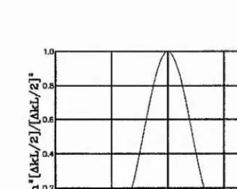
and the effect of phase m ism atch is included entirely in the factor of
sm'^{AkL/2)
(A6Z,/2)2 (2.39)
As shown in Fig. 2.7, when A k = 0 , then is equal to 1, and consequently, reaches its maxim um; when AkL/2=Tt, then and therefore, / ‘^^=0. Hence, the various phase-m atch acceptance param eters, such as angular and tem perature accep tance, are often defined by the factor of A k L / 2 = tt, as it will be discussed in later sections of this chai)ter.
W 0.1
d 0.2
- 2 - 1
AkL/2 (tt)
Figure 2.7: The effect of phase m ism atch
(2) S m a ll sig n a l s o lu tio n fo r p a r a m e tr ic a m p lific a tio n a n d o sc illa tio n ; W ith the frequency relationship of Up = Ug and assum ing a constant pum p field am plitude, and Op = Q's = a,' = 0, = cr., = cr, = 0, then the three coupled equations are reduced to two sim ultaneous differential equations [si(jnal and idler term s), which are
Es{z) = Eg(0)[cosh(<yz) - s'm\\{(jz)] - i - K s E p {0)E*{{)) smli{(jz)e' 2 ^
U
Ei[z) — E,(0)[cosh(/yz) - sinh(f/z)] — ?:-A',;Ep(0)EJ(0) sin h (f/z)c'T "
fJ
where
(2.40)
(2.41)
[image:42.612.186.357.325.461.2]CHAPTER 2. THEORETICAL BACKGROUND 40
-yg = (2.43)
Hi =
As — Y ^ ^ W sd e / y
(2.44)
T he s o lu tio n fo r d e p le te d in p u t
In the regime of depleted input, the plane-wave theory of the three-wave interaction w ith out absorption was first form ulated l)y A rm strong et al. [7] in 1902, who obtained explicit solutions for j)hoton fluxes in term s of the Jncobian elliptical sine function, sv,. Based on the original work, B aum gartiiier and Byer [8] reviewed and extended the coupled wave ecpiations for param etric am plification. In the work described here, the theoretical m od els for the calculation of conversion efficiency for SFG and OPOs are based on the exact analytic solution given in Ref.[8].
Numerical m ethods also play an im portant role in solving problems for the depleted case. W ith tlie great availability of com putational power, solving num erically the coupled wave equations has become a practical alternative to deriving analytical solutions. It has the significant advantage of allowing one to include in the modelling more physical effects, such as absorption and phase m ism atching, and therefore can give m ore accurate results than the analytic solution.
In this section, a. description is given of both m ethods.
(1 ) E x a c t s o lu tio n Using the polar forms of the coupled wave equations, Eq.(2.3()), and assum ing zero absorption for the three waves, then we have
dpi
d r c cos^ oqP2P3 sin 0
^ = sin 0
CH APTER 2. THEORETICAL BACKGROUND 41
^P3
_
br 113C cos^ «3 (2.45)
br A k + : : ^ (C '«,3 0 0 5 ^ 0 3 p 3
^2 P1P3 ^1 P2/I3
7?-2 COS^ «2 P2 COS^ ) COS
where 0 = AArr + <^(r) - (f)2{'r) - <^i(r).
An invariant, for the pa,ra.inet.ric conversion jirocess representing the power flow per unit area parallel to the direction of propagation is
or
W = {ii\pi cos^ a’l + 112P2 cos^ O'2 + '>kip3 cos^ «3)
W = l l ( 0 ) COS^ (X-[ + 1 2(0) C O B ^ 0 ' 2 + 1.3(0) cos^ (X3
Introducing the normalised dependent and independent variables given by
f
£oAfIl,
2\
I,- cos^ a,:CJiW 1/2
where i = 1,2, and 3, and
4dp//7r(7rIU)^/^7-(E0A1A2 A3 a 177,2^3 cos^ O i COS^ 0'2 COS^ 0 3)!/^
the resulting set of normalized coupled equation from Eq.(2.45) is
(2.46)
(2.47)
(2.48)
= —7/21/3 sin 6) (2.49)
bU2
bU3
7/, 177.3 sin 0
■= 77.1 W-2 sin ^
(2.50)
(2.51)
££ = A 5 + f ^ - ^ - ^ l c o s f l
CHAPTER 2. THEORETICAL BACKGROUND 42
where A S = A k r / ^ . The phase equation E([.(2.52) can be integrated with a substitution I'rom E q.(2.5i) to give
cos ^ ^A5'wg(0)^ (2.53)
and
r = (0 )7^2(0 ) 773( 0 ) cos 6/(0) + - A 5 t /§ ( 0 ) (2.54)
where F is a constant of integration. The solution to the norm alized coupled equations is based on integrating Eq.(2.51) and after substituting of the integration constant and the Manley-Rowe relations, the resultant integral is
1 d (ifg)
\ L (0)
7/| (m2 - 7/|) (ïUi - 7/,§) - ( r - ^A6'7./|) 1/ 2
(2.55)
where rui = 7/,j + 77,2, m2 = 77.2+ 7/J, and m.3 = ?7,j — 77-2, are the Manley-R,owe [11] relations. The cubic polynomial in the denom inator radical suggests the use of elliptic integrals as solutions. The three roots of the denom inator polynomial are placed in the order of 77,0^. > 77,^{, > 77.3 > 0. Two algebraic substitutions
„ ,2 _ ( " 3 - " 3 » )
(7 /,36 "3a
and
then convert the integral expression into the standard elhptic integrals [12]
'"'AO dy
i
f(^/'3c - '«3a) " [(^ f ) (1
-(2.56)
(2.57)
(2.58)
The inverse operation of the elliptic integral is a Jacohian elliptic function. The general solution for the normalized u values is
wg ( 0 = + ( " 1 - 77^^) (77^^ - 77g^) ' ( ( + 6 0) , 7 (2.59)
7/2 ( 0 = 77^(0) + 74(0) - « 1 (0 (2.60)
CHAPTER 2. THEORETICAL BACKGROUND 43
where
Ço = F(sii,-’ l y ( 0 ) ] ,7 ) ( » 4 - «L)"
and F (0 , r) is a standard elliptic, integral.
Num erical solutions of the above equations (2.59), (2.60) and (2.61), can lie obtained for particular nonlinear frequency conversion devices with given param eters, as will be discussed in the following sections of this chapter.
(2 ) N u m e ric a l s o lu tio n In cases where absorption m ay be considerable and it is unac ceptable to neglect the phase m ism atch to be zero, then it seems inevita,ble th a t num erical m ethods m ust be used to allow the inclusion of all those relevant effects.
The coupled wave equations (2.36) is a. stand alone system of four first-order ordinary differential equations at the form
P'i = fii'C PuP2, P3J ) (7: = 1 ,2 ,3 )
and
^ O{‘OP\^P2,P3,0)
In num erical work we can only obtain a [larticular solution, and this will consist of a table giving the values of p,- and 0 along side the corresjionding values of r. Thus in the case of the first-order differential equations, we need to specify not only the differential equation itself, but also the initial conditions
F?(/'()) — Pix) (?■ — 1,2, and 3)
and
^(/•o) = 0{)
Subject to certain m athem atical conditions, there is a unique solution for each equation in Eq.(2.36) which passes through the initial condition, (yp, p,o, 6*o).