International Research Journal of Engineering and Technology (IRJET)
e-ISSN: 2395-0056Volume: 06 Issue: 07 | July 2019 www.irjet.net p-ISSN: 2395-0072
© 2019, IRJET | Impact Factor value: 7.211 | ISO 9001:2008 Certified Journal
| Page 861
Circularly Polarized Ultra Wide Band Ring Shaped DGS Microstrip
Antenna for Wireless Applications
Uma Kumari
1, Tapan V. Nahar
2, Archana Mewara
3, Laxmi Narayan Balai
41
M-tech Scholar, Dept. of ECE, Yagyavalkaya Institute of Technology, Jaipur, India
2
Asst. Professor, Dept. of ECE, Global Institute of Technology, Jaipur, India
3
Asst. Professor, Dept. of ECE, Yagyavalkaya Institute of Technology, Jaipur, India
4
Head of Department, Dept. of ECE, Yagyavalkaya Institute of Technology, Jaipur, India
---***---
Abstract: This paper presents design of ring shaped
defected ground structure microstrip antenna. Proposed antenna is fed using microstrip line with quarter wave transformer for impedance matching. Antenna provides Ultra wide band characteristics and circular polarization. HFSS simulation tool is used for simulation of proposed antenna. Presented antenna provides 31.62% bandwidth at 2.15 GHz resonant frequency with minimum return loss and significant gain. It find applications in MSS (Mobile Satellite Services), Bluetooth, Satellite communicatio wireless networking etc. Comparative performance analysis between simulated antenna and fabricated antenna is also presented.
Keywords: Micro strip patch antenna, Circular Polarization Impedance Bandwidth, HFSS, Ultra Wide Band, Log periodic antenna.
1. INTRODUCTION
Now days, Compact circularly polarized microstrip antenna antenna plays an important role in satellite communication and airborne communication due to its small size, light weight, ease of fabrication and installation [1]. Microstrip antenna has serious limitation like small bandwidth, low gain, low efficiency and small power handling capacity. Bandwidth can be enhanced by increasing the height of substrate, decreasing the dielectric constant of substrate, non contact feeding techniques, cutting different shaped slots like H Shape [2], Bowtie[3], C shape[4], L Shape etc., Corporate feeding [5], stacked arrangement of patches [6] and defected ground structure [7-8]. The polarization is an important parameter to limit the wireless communication distance due to the resulting wave having an angular variation. The circular polarization provides solution of this problem. It allows the receiver to maintain constant received power at any wave angles [9]. Linearly polarization requires polarization matching between transmitting and receiving antenna but circularly polarized antenna solves this problem. Many researchers have worked on designing of the circular polarized antenna. For generating circular polarization, two equal amplitude orthogonal feed configurations are used. The
impedance bandwidth depends on feed configurations and feed positions. The bandwidth of circularly polarized antenna can be calculated where VSWR is less than 2 or reflection coefficient is less than 10 and axial ratio is less than 3 [10].
To reduce multipath fading and requirement of wide bandwidth, Ultra-wideband antenna comes in the role [11]. UWB antenna can transmit very short duration pulses accurately and efficiently as compared to traditional communication schemes sending sinusoidal waves. UWB Antenna provides high data transfer rates, simple construction of hardware, less power consumption and omnidirectional radiation pattern [10]. For integrating circular polarization with Ultra wide band characteristics coplanar wave guide structure, aperture couple techniques, Kotch fractal geometry, Matching Stubs, log periodic structure and asymmetrical structures are used [11-16].
For applications of future technologies of wireless communication like cognitive radio, ground penetrating radar and RFID, UWB and circularly polarized antenna was mostly preferred by researchers [17-19].
In this paper, microstrip ring shaped antenna is designed. Defected Ground Surface is used to achieve broad bandwidth. All the parameters are optimized to achieve circular polarization with good bandwidth and minimum losses. Dimension of three elements having circular shaped is. Proposed antenna geometry is simulated using HFSS simulation tool. Patch geometry is fabricated on FR4 substrate of 4.4 dielectric constant. All the necessary parameters like bandwidth, VSWR, Axial Ratio and return loss are compared between simulated antenna and fabricated antenna.
2. ANTENNA DESIGN
International Research Journal of Engineering and Technology (IRJET)
e-ISSN: 2395-0056Volume: 06 Issue: 07 | July 2019 www.irjet.net p-ISSN: 2395-0072
© 2019, IRJET | Impact Factor value: 7.211 | ISO 9001:2008 Certified Journal
| Page 862
using microstrip line of 8*2.4 square mm. A quarter wave line is used between feed line and patch having dimensions 12*.96 square mm. Substrate of FR4 having dielectric constant 4.4 and loss tangent 0.025 is used. The thickness of substrate is taken of 1.6 mm. Ground plane is optimized at 20 mm from feed point. Substrate area is 60 mm by 50 mm. Simulation is carried out using HFSS Simulation tool.
Fig -1: Proposed Ring Shaped Defected Ground Antenna
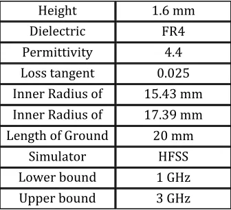
[image:2.612.325.578.80.204.2]Proposed antenna parameters are shown in Table 1.
Table -1: Proposed Antenna Parameters
Height 1.6 mm
Dielectric
substrate FR4
Permittivity 4.4
Loss tangent
(tanδ) 0.025
Inner Radius of
Patch 15.43 mm
Inner Radius of
Patch 17.39 mm
Length of Ground
Plane 20 mm
Simulator HFSS
Lower bound
frequency 1 GHz
Upper bound
frequency 3 GHz
3. SIMULATION RESULTS
Proposed antenna is simulated on HFSS virtual tool. All the simulation results are discussed in this section.
3.1 Reflection coefficient v/s frequency plot
Reflection coefficient represents the reflections to source due to impedance mismatch. Simulated S11 versus frequency plot is represented in Figure 2. It shows that antenna provides less than 10 dB return loss from 1.8 GHz to 2.48 GHz and resonates at 2.15 GHz with minimum reflection coefficient of -23.8596 dB. Calculated Impedance Bandwidth is 31.62 %.
Fig -2: Reflection coefficient versus frequency plot
3.2 Axial Ratio plot
Axial Ratio variation is presented in figure 3. It is observed that proposed antenna provides axial ratio 2.37 dB at 2.3 GHz which is less than 3 dB at specific frequency which presents the circular polarization nature.
Fig -3: Axial Ratio plot
3.3 Radiation Pattern
Radiation pattern represents the radiation performance of antenna in terms of space coordinates. Figure 4 represents radiation pattern in which gain is plotted in terms of space coordinates. Maximum gain of 1.5963 is achieved at resonant frequency.
Fig -4: Radiation pattern
Three dimensional radiation pattern is shown in figure 5. It is shown in the Figure of Eight shape which is due to defected ground shape.
1.00 1.25 1.50 1.75 2.00 2.25 2.50 2.75 3.00
Freq [GHz] -25.00 -20.00 -15.00 -10.00 -5.00 0.00 d B(S t(p a tch _ T 1 ,p a tch _ T 1 )) HFSSDesign1
XY Plot 64 ANSOFT
m 1 m 2
m 3
Curve Info dB(St(patch_T1,patch_T1)) Setup1 : Sw eep Name X Y
m 11.8000 -10.0225 m 22.4800 -9.8921 m 32.1500 -23.8596
-200.00 -150.00 -100.00 -50.00 0.00 50.00 100.00 150.00 200.00 Theta [deg] 0.00 10.00 20.00 30.00 40.00 50.00 60.00 70.00 80.00 d B(A xi a lR a ti o Va lu e ) HFSSDesign1
XY Plot 66 ANSOFT
m1
Curve Info dB(AxialRatioValue) Setup1 : LastAdaptive Freq='2.3GHz' Phi='0deg'
dB(AxialRatioValue) Setup1 : LastAdaptive Freq='2.3GHz' Phi='90deg' Name X Y
m1 86.0000 2.3748
-23.00 -16.00 -9.00 -2.00 90 60 30 0 -30 -60 -90 -120 -150 -180 150 120 HFSSDesign1
Radiation Pattern 10 ANSOFT
m1
Curve Info dB(GainTotal) Setup1 : LastAdaptive Freq='2.3GHz' Phi='0deg'
dB(GainTotal) Setup1 : LastAdaptive Freq='2.3GHz' Phi='90deg' Name Theta Ang Mag
[image:2.612.39.289.185.303.2] [image:2.612.327.578.315.448.2] [image:2.612.78.246.378.531.2] [image:2.612.401.498.548.649.2]International Research Journal of Engineering and Technology (IRJET)
e-ISSN: 2395-0056Volume: 06 Issue: 07 | July 2019 www.irjet.net p-ISSN: 2395-0072
© 2019, IRJET | Impact Factor value: 7.211 | ISO 9001:2008 Certified Journal
| Page 863
Fig -5: Radiation pattern in 3D
3.4 Smith Chart
Smith Chart is presented in figure 6. It shows the matching of antenna. The circles represent the resonant frequencies where losses are minimum. It is shown that impedance is 56.76 Ohm which is vary closed to 50 Ohm, suggests good matching.
Fig -6: Smith Chart in 3D
3.5 VSWR versus frequency Plot
VSWR versus frequency plot is represented in Figure 7. It is shown that VSWR is very close to unity at resonant frequency which suggests excellent impedance matching.
Fig -7: VSWR versus frequency plot
4. FABRICATED ANTENNA & MEASURED RESULTS
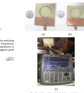
Proposed antenna is fabricated on FR4 substrate having dielectric constant of 4.4. The fabricated antenna’s front view, back view and measurement setup with Vector Network Analyzer is shown in figure 8. The thickness of substrate is 1.6 mm.
(a) (b)
(c)
Fig -7: (a) Front View (b) Back View (c) Fabricated
Antenna with Measurement Setup
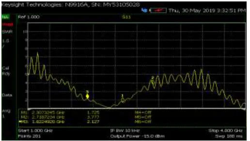
Fabricated Ring Shaped DGS antenna is connected to Vector Network Analyzer of Keysight Technologies (upto 14 GHz) using coaxial cable at Global Institute of Technology. The measured result shows the significant bandwidth. Figure 8 represents measured reflection coefficient (S11) versus frequency plot. The graph indicates that reflection coefficient is less than -10dB from 1.82 GHz to 2.30 GHz. Minimum return loss is -29.5 dB at 2.1 GHz. Measured % Bandwidth 22.85 % at 2.1 GHz. It is shown that Proposed antenna provides significant performance at frequencies from from 1.82 GHz to 2.3 GHz.
0.00 -0.50 -0.70 -0.80 -0.90 -2.00-1.50-1.30-1.20-1.15-1.10-1.050.00
0.05 -0.05 0.02
-0.02 0.01
-0.01 0.01
-0.01 0.00
-0.00
0.00 0
10 20 30 40 50 60 70 80 90 100 110 120 130 140 150 160 170 180 -170 -160
-150 -140
-130 -120
-110 -100 -90 -80 -70
-60 -50
-40 -30
-20 -10
HFSSDesign1
Smith Chart 2 ANSOFT
m 1
Curve Info Zt(patch_T1,patch_T1) Setup1 : Sw eep Name Freq Ang Mag RX
m 1 2.1500-1.1306 56.7646 -1.0359 - 0.0007i
1.00 1.25 1.50 1.75 Freq [GHz]2.00 2.25 2.50 2.75 3.00 1.00
2.00 3.00 4.00 5.00 6.00 7.00 8.00 9.00
VS
W
R
t(p
atch
_
T
1)
HFSSDesign1
XY Plot 65 ANSOFT
m 1
Curve Inf o VSWRt(patch_T1) Setup1 : Sw eep Name X Y
[image:3.612.234.559.72.429.2] [image:3.612.115.210.287.388.2] [image:3.612.39.289.485.582.2]International Research Journal of Engineering and Technology (IRJET)
e-ISSN: 2395-0056Volume: 06 Issue: 07 | July 2019 www.irjet.net p-ISSN: 2395-0072
© 2019, IRJET | Impact Factor value: 7.211 | ISO 9001:2008 Certified Journal
| Page 864
Fig -8: Measured reflection coefficient versus
frequency plot
Proposed antenna provides good matching between feed line and patches which is represented by VSWR versus frequency plot represented in Figure 9. VSWR is very close to unity at resonant frequency and less than 2 from 1.82 GHz to 2.30 GHz. There are losses due to cable, fabrication discontinuities and solder connections of port.
Fig -9: Measured VSWR versus frequency plot
5. COMPARATIVE ANALYSIS
There is great similarity in the measured result of fabricated antenna with simulated results. Simulated result shows that simulated antenna provides less than 10 dB return loss from 1.8 GHz to 2.48 GHz and resonates at 2.15 GHz with minimum reflection coefficient of -23.8596 dB. Measured result of fabricated antenna represents that antenna is tuned from 1.82 GHz to 2.30 GHz and resonates at 2.1 GHz with S11 of -29.5 dB. Measured bandwidth of fabricated santenna is 22.85 % while Bandwidth of Simulated antenna is 31.62 %. Measured Results of fabricated antenna is varied from simulated results due to cable loss, fabrication discontinuities and solder connection. Proposed antenna provides significant
performance for applications such as MSS (Mobile Satellite Services), Bluetooth, wireless networking etc.
9. CONCLUSION
Design of Circularly Polarized Ultra Wide Band Ring Shaped Microstrip Antenna for Wireless Applications is presented. Proposed antenna is fabricated and measured results shows significant performance with good bandwidth and minimum return loss. It can be used applications such as MSS (Mobile Satellite Services), Bluetooth, wireless networking etc.
REFERENCES:
[1] Manavalan Saravanan and Madihally Janardhana Srinivasa Rangachar “Design of Rhombus-Shaped Slot Patch Antenna for Wireless Communications”, Hindawi Journal of Computer Networks and Communications,
Volume 2019, Article ID 5149529, 7 pages,
https://doi.org/10.1155/2019/5149529
[2] Sudhir Bhaskar and Sachin Kumar Gupta,”Bandwidth Improvement of Microstrip Patch Antenna using H-Shaped Patch”, IJERA,Vol.2,Issue 1, Jan-Feb.2012,pp. 334-338
[3] Tapan Nahar and O.P.Sharma, “A Modified Approach for Bandwidth Enhancement of Microstrip Patch Antenna in L Band,” National Seminar on Advancement in Wireless and Optical Applications (NSAWOA-2014) Proceedings, First Edition, Jan. 2014.
[image:4.612.39.287.81.244.2] [image:4.612.36.294.366.512.2][4] Surendra Kumar Daiya, Tapan V. Nahar, Archana Mewara, Laxmi Narayan Balai, “Effect of Ground Plane Length on Bandwidth of Circularly Polarized C- Slotted Microstrip Patch Antenna for Satellite Applications”, IJSRD - International Journal for Scientific Research & Development| Vol. 5, Issue 12, 2018 | ISSN (online): 2321-0613
[5] Tapan Nahar and O.P.Sharma, “A Modified Multiband Bowtie Antenna Array used for L band Applications,” International Journal of Engineering Research & Technology (IJERT), Vol.3, Issue 11, ISSN: 2278-0181, Nov. 2014.
[6] Tapan Nahar and O.P. Sharma, “A Modified Approach for Bandwidth Enhancement of Microstrip Patch Antenna,” Biyani International Conference (BICON-13), Vol. 8, Sept. 2013.
International Research Journal of Engineering and Technology (IRJET)
e-ISSN: 2395-0056Volume: 06 Issue: 07 | July 2019 www.irjet.net p-ISSN: 2395-0072
© 2019, IRJET | Impact Factor value: 7.211 | ISO 9001:2008 Certified Journal
| Page 865
[8]Surendra Kumar Daiya, Tapan V. Nahar, Archana Mewara, Laxmi Narayan Balai, “Performance Comparisons of Circularly Polarized Meandered Slotted Microstrip Patch Antennas for Satellite Applications” , IJSRD - International Journal for Scientific Research & Development| Vol. 5, Issue 12, 2018 | ISSN (online): 2321-0613
[9] Thoetphan Kingsuwannaphong, Vitawat Sittakul, “Compact Circular Polarization Microstrip Antenna”, International Conference on Communication and Signal Processing, April 6-8, 2016.
[10] Prashant Chaudhary1 and Ashwani Kumar, “Compact Ultra-Wideband Circularly Polarized CPW-Fed Monopole Antenna”, International Journal of Electronics and Communications, 2019, doi: https://doi.org/10.1016/ j.aeue.2019.05.025
[11] Madhuri Sahal, Madhuri Sahal, “Review of Circular Polarization techniques for design of Microstrip Patch Antenna”, Research Gate, 2016.
[12] Jia Wei, Xing Jiang and Lin Peng, “Ultra Wideband and High Gain Circularly Polarized Antenna with Double-Y-Shape Slot”, IEEE Antennas And Wireless Propagation Letters, 2016.
[13] Karavilavadakkethil C. Prakash, Puthiyapurayil V. Vinesh, Manoj Mani, Sumitha Mathew, Pezholil Mohanan, and Kesavath Vasudevan, “Printed Circularly Polarised Asymmetric Ultra-Wideband Antenna”, Progress In Electromagnetics Research M, Vol. 74, 179–189, 2018
[14] Nickolas K., Dimitrios E. A., Manos T., JohnP. RF MEMS Sequentially Reconfigurable Sierpinski Antenna on a Flexible, Organic Substrate With Novel DC Biasing Technique, IEEE/ASME Journal of Micro Electromechanical System, vol 16, Issue 5,pg. 1185 -1192, 2007
[15] S.B.Byun, J.-A.Lee, J.-H.Lim, and T.Y.Yun.
Reconfigurable ground-slotted patch antenna using PIN diode switching, ETRIJ, vol. 29, pp. 832–834, Dec. 2007.
[16] S.B.Byun, J.-A.Lee, J.-H.Lim, and T.Y.Yun.
Reconfigurable ground-slotted patch antenna using PIN diode switching, ETRIJ, vol. 29, pp. 832–834, Dec. 2007.
[17] Nickolas K., Dimitrios E. A., Manos T., JohnP. RF MEMS Sequentially Reconfigurable Sierpinski Antenna on a Flexible,Organic Substrate With Novel DC Biasing Technique, IEEE/ASME Journal of Micro Electromechanical System, vol 16, Issue 5,pg. 1185 -1192, 2007
[18] A.H.Ramadan, K.Y.Kabalan, A.El-Hajj, S.Khoury and M.Al-Husseini. A Reconfigurable U-Koch Microstrip Antenna for Wireless Application, Progress In Electro magnetics Research, PIER 93, pp.355-367,2009.