http://www.scirp.org/journal/opj ISSN Online: 2160-889X ISSN Print: 2160-8881
Investigation of a New Waveguide Structure
Based on Negative Index Material for
Optoelectronic Applications
Nour El Houda Hissi1, Bouchra Mokhtari1*, Saida Bahsine1, Noureddine Cherkaoui Eddeqaqi1,
Mohammed Musa Shabat2
1Physics Department, Moulay Ismail University, Meknes, Morocco 2Physics Department, Islamic University of Gaza, Gaza, Palestine
Abstract
In this work, a waveguide structure consisting of a new artificial negative in-dex material (NIM) surrounded by a nonlinear cover and a ferrite (YIG) sub-strate has been designed and investigated. We apply the boundary conditions and impose the condition of negative effective permeability of the ferrite slab to derive the dispersion relation related to the proposed structure. The NIM permittivity and permeability are not constant and depend on the operating frequency. The dispersion properties of the nonlinear electromagnetic surface waves (NEM) are analyzed and the associated propagation index is calculated. Results show that the dispersion could be tuned and controlled by selecting the NIM film thickness and the film-cover interface nonlinearity. The pro-posed structure is supporting unusual types of NEM surface waves having a non-reciprocal behavior widely used in designing optoelectronic devices.
Keywords
Negative Index Material, Nonlinearity, Ferrite Substrate, Waveguide, Dispersion Relation, Non-Reciprocal Behavior
1. Introduction
Negative index materials (NIM) are artificially designed structures with negative permittivity and permeability providing a route to create potential devices with fascinating electromagnetic properties that cannot be obtained with natural ma-terials [1]-[6]. The history of these materials began with Veselago [7] who pre-dicted the existence of such materials with unexpected optical properties. One particularly interesting NIM device is an NIM based waveguide structure that has potentially interesting applications. Recent experimental demonstrations of How to cite this paper: Hissi, N. El H.,
Mokhtari, B., Bahsine, S., Eddeqaqi, N.C. and Shabat, M.M. (2017) Investigation of a New Waveguide Structure Based on Nega-tive Index Material for Optoelectronic Ap-plications. Optics and Photonics Journal, 7, 123-132.
https://doi.org/10.4236/opj.2017.77012
Received: May 23, 2017 Accepted: July 11, 2017 Published: July 14, 2017
Copyright © 2017 by authors and Scientific Research Publishing Inc. This work is licensed under the Creative Commons Attribution International License (CC BY 4.0).
novel composite materials with a negative refractive index [8]-[13] open up an exceptional possibility to design novel types of devices where electromagnetic waves propagate in a nonconventional way. In parallel, more linear and nonli-near metamaterials have been studied theoretically and experimentally from mi-crowave to optical frequencies [14]-[19]. In most investigations dealing with the planar nonlinear waveguides, the basic attention has been given to the electro-magnetic surface waves [20]. Despite these advanced studies, new modes of propagation due to the variation of NIM’s parameters (permittivity and permea-bility) in new NIM waveguide were not investigated. In this paper, we aim at studying a magnetic structure with a negative index material (NIM) core sur-rounded by a nonlinear cover cladding and a ferrite substrate, where unusual electromagnetic surface waves-basically not existing in a conventional wave-guide-are examined [21]. The present work is an extension and an integration of the previous work [12] [21]. We focus on studying the considered structure and calculate the dispersion equations for TE modes. We present and discuss the as-sociated propagation wave index and the film cover interface nonlinearity versus the normalized frequency and other various physical parameters of the NIM layer. The numerical results are given in order to draw attention on the variation in surface wave’s behavior propagating in different waveguide structures, as in the considered waveguide based on NIM core [13] [22] having negative permit-tivityε2 and permeabilityμ2both depending on the operating frequencyω, the
NEM waves propagate in a non-conventional way comparing with those propa-gating in classical structures. Finally, conclusions are given for the various re-sults of this study. This work’s rere-sults can be used in designing and fabricating microwave devices for a wide range of applications as isolators, sensors, circula-tors, solar cells…
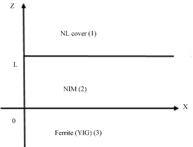
[image:2.595.204.539.630.704.2]2. Proposed Waveguide Structure and Simulation Approach
Figure 1 displays the configuration of the considered waveguide structure. We shall assume that the waveguide consists of an NIM core of width L bounded by a nonlinear cover and a gyromagnetic ferrite substrate. The waveguide is as-sumed to have infinite extent in the x and y directions. The dispersion equation is given for stationary TE waves only propagating in the x-direction. A static magnetic field is applied in the y direction transverse to the direction of propa-gation.
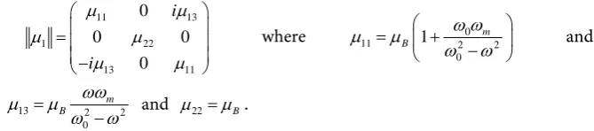
The magnetic permeability tensor of the ferrite (YIG) substrate is defined as [21] where ω is the surface wave operating frequency:
11 13 1 22 13 11 0 0 0 0 i i µ µ µ µ µ µ = − where 0
11 2 2
0 1 m B ω ω µ µ ω ω = + −
and
13 2 2
0 m B ωω µ µ ω ω =
− and µ22=µB.
0 0H0
ω =γµ is the Larmor frequency, ωm =γµ0M0 is the magnetic
Figure 1. The schematic of the proposed waveguide consisting of negative index film bounded by a ferrite (YIG) substrate and a nonlinear (NL) cover.
the applied magnetic field and µ0M0 is the dc saturation magnetization. The
NIM core has it effective permittivity
( )
2
2 1 2
p
ω ε ω
ω
= − with the plasma fre-
quency ωp in the GHz range and it effective magnetic permeability
( )
22 1 2 2
r
Fω
µ ω
ω ω = −
− , with the resonance frequency ωr in the GHz range; F is
the filling factor. We choose ωr =4 GHz and
F = 0.56 [22]. The nonlinear dielectric cover has it dielectric function isotropic and depends on the electric field. It can be written as for TE waves:
2
NL
f Ey
ε =ε +α where εf is the linear part of the dielectric function and α
is the nonlinear coefficient [21].
The TE fields have the following forms, where q is the propagation constant:
( )
(
0, yei qx t , 0)
E= E −ω
( ) ( )
(
xei qx t, 0, zei qx t)
H= H −ω H −ω (1)
We apply the transverse electric fields into Maxwell's equations:
0 i
E iωµ µH
∇ × = (2)
0 i
H iωε εE
∇ × = − (3)
In the ferrite (YIG) substrate, the plane wave equation is: ( )
( ) 1
2
1 2 1
2 0
y
y
E
E
z η
∂
− =
∂ (4)
where 2 2 2 2
(
2)
1 q 2 v c 0 v c
c
ω
η = − µ ε =η β −µ ε and
(
2 2)
11 13 11
v
Voigt permeability, 0 q β η =
is the effective mode index, 0
c
ω
η = is the propa-
gation constant in the vacuum, and c is the speed of light. In medium (2), the plane wave equation is:
( ) ( ) 2 2 2 2 2 2 0 y y E E z η ∂ − =
∂ (5)
where:
2 2
2 2 2
2 2 2 2
2 2 1 2 2 1 2 0 1 2 2 1 2
p p r r F F q c ω ω
ω ω ω
η η β
ω ω ω ω ω ω
= − − − − = − − − −
In the nonlinear dielectric cover, the plane wave equation is: ( ) ( ) 3 2 3 2 3 2 0 y y E E z η ∂ − =
∂ (6)
where:
(
)
2
2 2 2 2
3 q 2 f f 0 f f
c
ω
η = − µ ε =η β −µ ε
Applying the boundary conditions at z = 0 and z = L to the plane wave equa-tions soluequa-tions, we obtain the dispersion equation as follows:
(
)(
) (
)(
)
2 22 2 2 3 2 2 2 2 3 2 e 0
L
R v R v η
η − µ η η µ − − η + µ η η µ + − = (7)
where:
(
11 1 13)
11R= −µ η +µ q µ µν and v=tanhη3
(
z0−L)
z0 is a constant that we can determine from the boundary conditions.
From the nonlinear dispersion equation we can easily obtain the film-cover interface nonlinearity:
( )
( )
2(
)
2 3 3 2
2 0
1
2 Ey L v
η α η = −
(8)
2 2
3 2 2 3
W v
W
η η
η µ µ η
− =
+
,
(
)
222 2 2 2 e L R W R η η µ η µ − + = −
3. Results and Discussions
In order to have surface waves in the proposed waveguide structure, the effective ferrite permeability should be less than zero. This constraint and condition should be implemented on the solution of the dispersion equation. We numeri-cally solve the Equation (7) in order to find out the propagation wave index
ver-sus the operating normalized frequency Ω =ω ωm for different NIM film
thicknesses L, where β =cq ω. The numerical computations were performed the parameter values [15]: µ0H0=0.550T , µ0M0=0.1750T , εc=1 ,
2.25
f
ε = , α =1.55 10× −10m2⋅V−2, 1.25 B
Figure 2 shows the computed effective Voigt permeability µv versus the
normalized operating frequency. For numerical calculation, we set the frequency within the range from ω ω0
(
0+ωm)
to ω ω0+ m for µv≤0.Figure 3 shows discontinuity, that represents the forbidden band of the NIM waveguide. It clearly illustrates that the surface modes cannot propagate for L = 4 mm.
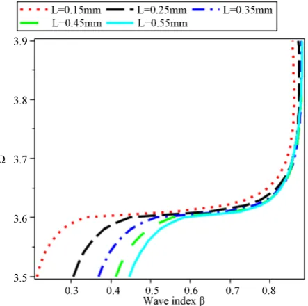
[image:5.595.266.484.485.701.2]Figure 4 shows the NEM surface waves dispersion in the backward wave di-rection. Different NIM slab thicknesses are considered to show it effect on the propagation. The effective wave index versus the operating frequency has a new
Figure 2. The effective Voigt permeability versus the
norma-lized frequency.
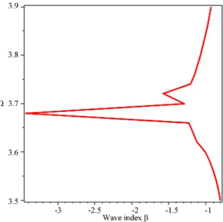
Figure 3. The dependence of Ω on the wave index for the
Figure 4. NEM surface wave’s dispersion in the backward wave direction for different values of the NIM slabs thickness.
different behavior, we can observe that when the value of L increases from 0.15 mm to 0.55 mm, the wave index varies from 0.2 to 0.55, above the value
0.6
β = , the propagation modes become identical and have practically the same
trajectory.
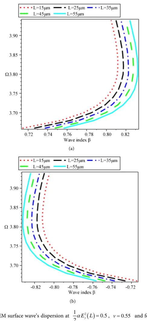
Figure 5 exhibits the nonlinear surface wave’s dispersion curves in the back-ward and the forback-ward directions for different NIM slab thicknesses with the film cover non-linearity value kept constant. The curves present a linear increase with practically the same direction. Moreover all modes are propagating in the negative region for β negative in the forward direction and propagating in the
positive region for β positive in the backward direction. We conclude that the
NIM having it permittivity and permeability depending on the frequency is changing the forward direction to the backward direction and this behavior is particular to NIM based waveguides.
It is concluded that by adjusting or tuning some physical parameters in such waveguide structure, the wave propagation direction could be reversed. This feature or characteristics could be used in design some future optoelectronics devices.
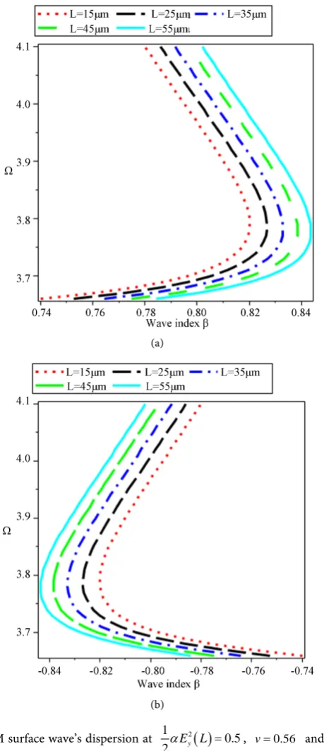
Figure 6 shows NEM surface wave’s dispersion curves in the backward and the forward directions for different NIM slab thicknesses and for a different val-ue of nonlinearity v=tanhη3
(
z0−L)
with the film cover non-linearity value kept constant. We found that two different values of the frequency correspond to the same value of the wave index; this also means that both figures show a new behavior and different stability features. This behavior is very important to design microwave devices.(a)
[image:7.595.254.498.67.599.2](b)
Figure 5. NEM surface wave’s dispersion at 1 2
( )
0.5
2αEy L = , v=0.55 and for different
values of the NIM slab thickness (a) is the backward wave direction and (b) is forward wave direction.
4. Conclusion
backward propagation direction (or forward propagation direction) correspond two operating frequencies. These effects are in contrast with those obtained in a conventional waveguide structure and could be used in designing and imple-menting integrated microwave devices based on the non-reciprocal behavior as isolators, sensors and circulators for military services, solar cells, telecommuni-cations, automatic access control systems and medical equipment.
(a)
[image:8.595.261.491.174.706.2](b)
Figure 6. NEM surface wave’s dispersion at 1 2
( )
0.5
2αEy L = , v=0.56 and for different
Acknowledgements
One of the authors (M.M.S) thanks Prof. Dr. Daniel M. Schaadt, Institute of Energy Research and Physical Technologies, Technical University of Clausthal, Germany for many valuable suggestions and fruitful discussions during the de-velopment of this work.
References
[1] Wu, R.X. (2005) Effective Negative Refraction Index in Periodic Metal-Ferrite- Metal Film Composite. Journal of Applied Physics, 97, 076105-076108A.
https://doi.org/10.1063/1.1883718
[2] Powell, D.A., Hannam, K., Shadrivov, I.V. and Kivshar, Y.S. (2011) Near-Field In-teraction of Twisted Split-Ring Resonators. Physical Review B, 83, 1-6.
https://doi.org/10.1103/PhysRevB.83.235420
[3] Kapitanova, P.V., Slobozhnanyuk, A.P., Shadrivov, I.V., Belov, P.A. and Kivshar, Y.S. (2012) Competing Nonlinearities with Metamaterials. Applied Physics Letters, 101, 1-4. https://doi.org/10.1063/1.4768945
[4] Zhanyuka, P.S., Kapitanovaa, P.V., Shadrivova, I.V., Belova, P.A. and Kivshara, Y. S. (2012) Metamaterials with Tunable Nonlinearity. Journal of Theoretical and
Expe-rimental Physics Letters, 95, 613-617.
https://doi.org/10.1134/S0021364012120156
[5] Thapa, K.B., Vishwakarma, A., Singh, R. and Ojha, S.P. (2010) Electromagnetic Wave Propagation through Single Negative Index Material. Journal of Ovonic
Re-search, 6, 105-115.
[6] El-Amassi, D.M., El-Khozondar, H.J. and Shabat, M.M. (2015) Efficiency En-hancement of Solar Cell Using Metamaterials. International Journal of Nano
Stu-dies and Technology, 4, 84-87. https://doi.org/10.19070/2167-8685-1500016
[7] Veselago, V.G. (1968) The Electrodynamics of Substances with Simultaneously Negative Values ofεand μ. Soviet Physics Uspekhi, 10, 509-514.
https://doi.org/10.1070/PU1968v010n04ABEH003699
[8] Shadrivov, I.V., Zharova, N.A., Zharov, A.A. and Kivshar, Y.S. (2004) Defect Modes and Transmission Properties of Left-Handed Band Gaps Structures. Physical
Re-view E, 70, 1-6. https://doi.org/10.1103/PhysRevE.70.046615
[9] Shadrivov, I.V. (2004) Nonlinear Guided Waves and Symmetry Breaking in Left- Handed Waveguides. Physics Optics, 2, 175-180.
https://doi.org/10.1016/j.photonics.2004.08.003
[10] Smith, D.R., Schuring, D., Rosenblutch, M., Schultz, S., Ramakrishna, S.A. and Pendry, J.B. (2003) Limitations on Subdiffraction Imaging with a Negative Refrac-tive Index Slab. Applied Physics Letters, 82, 1506-1508.
https://doi.org/10.1063/1.1554779
[11] Darmanyan, S.A., Kobaykov, A. and Chowdhury, D.Q. (2006) Nonlinear Guided Waves in a Negative-Index Slab Waveguide. Physics Letters A, 363, 159-163.
https://doi.org/10.1016/j.physleta.2006.10.087
[12] Hissi, N., Mokhtari, B., Eddeqaqi, N.C., Shabat, M.M. and Atangana, J. (2016) Non-linear Surface Waves at Ferrite-Metamaterial Waveguide Structure. Journal of Mo-
dern. Optic, 63, 1552-1557. https://doi.org/10.1080/09500340.2016.1161094
https://doi.org/10.1007/s11082-013-9724-y
[14] Soukoulis, C.M., Liden, S. and Wegener, M. (2007) Negative Refraction Index at Optical Wavelengths. Science, 315, 47-49. https://doi.org/10.1126/science.1136481
[15] Shalaev, V.M., Cai, W., Chettiar, U.K., Yuan, H., Andrey, K., Sarychev, V., Drachev, P. and Kildishev, A.V. (2005) Negative Index of Refraction in Optical Metamate-rials. Optics Letters, 30, 3356-3358. https://doi.org/10.1364/OL.30.003356
[16] Shalaev, V.M. (2007) Optical Negative-Index Metamaterials. Nature, Photonics, 1, 41-48. https://doi.org/10.1038/nphoton.2006.49
[17] Yao, J., Liu, Z., Liu, Y., Wang, Y., Sun, C., Bartal, G., Stacy, A.M. and Zhang, X. (2008) Optical Negative Refraction in Bulk Metamaterials of Nanowires. Science, 321, 930. https://doi.org/10.1126/science.1157566
[18] Zharov, A.A., Shadrivov, I.V. and Kivshar, Y.S. (2003) Nonlinear Properties of Left-Handed Metamaterials. Physical Review Letters, 91, 1-4.
https://doi.org/10.1103/PhysRevLett.91.037401
[19] Lapine, M., Gorkunov, M. and Ringhofer, K.H. (2003) Nonlinearity of a Metama-terial Arising from Diode Insertions into Resonant Conductive Elements. Physical
Review E, 67, 065601. https://doi.org/10.1103/PhysRevE.67.065601
[20] El-Khozondar, H.J., Al-Sahhar, Z.I. and Shabat, M.M. (2010) Electromagnetic Sur-face Waves of a Ferrite Slab Bounded by Metamaterials. International Journal of
Electronics and Communication, 64, 1063-1067.
https://doi.org/10.1016/j.aeue.2009.09.003
[21] Shabat, M.M. and Pelzl, J. (1996) Nonlinear Electromagnetic Surface Waves in a Magnetic Structure. Infrared Physics and Technology, 37, 265-270.
https://doi.org/10.1016/1350-4495(95)00051-8
[22] Essadqui, A., Ben-Ali, J., Bria, D., Djafari-Rouhani, B. and Nougaoui, A. (2010) Photonic Band Structure of 1D Periodic Composite System with Left Handed and Right Handed Materials by Green Function Approach. Progress in Electromagnetics
Research B, 23, 229-249. https://doi.org/10.2528/PIERB10032404
Submit or recommend next manuscript to SCIRP and we will provide best service for you:
Accepting pre-submission inquiries through Email, Facebook, LinkedIn, Twitter, etc. A wide selection of journals (inclusive of 9 subjects, more than 200 journals)
Providing 24-hour high-quality service User-friendly online submission system Fair and swift peer-review system
Efficient typesetting and proofreading procedure
Display of the result of downloads and visits, as well as the number of cited articles Maximum dissemination of your research work