Meas. Sci. Technol.14(2003) 1275–1279 PII: S0957-0233(03)52303-7
Contact force sensor for artificial hands
with a digital interface for a controller
Paul H Chappell and Jamie A Elliott
Electronics and Computer Science, University of Southampton, Highfield, Southampton SO17 1BJ, UK
E-mail: [email protected]
Received 13 August 2002, in final form 18 March 2003, accepted for publication 12 June 2003
Published 16 July 2003
Online at stacks.iop.org/MST/14/1275
Abstract
A force sensor, for use with an artificial hand, needs to be small, robust, low power, cheap and easily interfaced to a controller using digital techniques. The prototype featured in this paper uses capacitance effects to measure the strain on an elastic polymer foam. Low power consumption results in a device that can be supplied from a miniature battery thereby requiring only signal wires to the controller. A non-linear model accurately describes the characteristic of the sensor, requiring the estimation of only three
parameters. The device has been tested up to 20 N but is capable of measuring greater forces.
Keywords: force, capacitance, polymer foam, non-linear model, artificial hands, robot feedback control
(Some figures in this article are in colour only in the electronic version)
1. Introduction
In the design of an artificial hand for the disabled, there is overriding requirement to make the prosthesis as lightweight as possible and to constrain the mass to less than 500 g [1]. Yet, in order to improve the functionality and usefulness of a hand, the addition of feedback control and hence the measurement of finger position, object-slip and the focus for this paper, force (or touch), is required. Each sensor must fit the appropriate place in the structure of a hand but also is required to be as small as possible. For an anthropomorphic hand the palmar side contains force sensors especially at the fingertips. Typical commercial hands do not have closed loop controls with force feedback and only a few designs have sensors embedded in their structure.
For this application, the standard features for any transducer are required (low temperature drift, good accuracy, good repeatability and insusceptibility to EM interference) and the specifications shown in table 1.
[image:1.595.336.506.520.650.2]No single method is appropriate for tactile sensing [2] and the aim is to select a suitable technology with the least shortcomings. The majority of tactile sensing research has been conducted in the area of robotics. Unfortunately this has
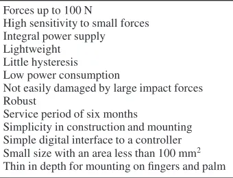
Table 1.Specifications for a prosthetic force sensor. •Forces up to 100 N
•High sensitivity to small forces •Integral power supply •Lightweight •Little hysteresis •Low power consumption
•Not easily damaged by large impact forces •Robust
•Service period of six months
•Simplicity in construction and mounting •Simple digital interface to a controller •Small size with an area less than 100 mm2 •Thin in depth for mounting on fingers and palm
limited application within prosthetics due to the size, mass, power or signal sensing factors.
d
Force, F
Moving plate
[image:2.595.311.537.81.218.2]dielectric Fixed plate
Figure 1.Parallel plate capacitor with centre elastic material.
power consumption. Optical transmission, using an LED and photodiode at either ends of an elastic tube, has provided a reliable sensor with integral acoustic slip sensing [4]. However this device is complex to manufacture. Hall effect sensors are a low cost solution but need to be turned off by the controller when not in use otherwise they dissipate too much battery power with the subsequent increase in system complexity [5]. Piezoelectric sensors require signal-conditioning circuits for static measurement and there is some difficulty in separating the piezoelectric and pyroelectric effects. However this technology may provide a good solution with small size and low power. Zhu and Spronck [6] have reported that capacitive tactile sensors have little hysteresis, creep and temperature dependency making them an attractive technology for object manipulation.
The market for artificial hands is relatively small and prohibits the use of high cost sensors using a sophisticated technology [6–8]. However a special sensor which is easy to manufacture in low volumes would provide an incentive to the introduction of closed loop control into commercial prosthetic design with the subsequent improvement in functionality. The novelty of the work presented in this paper is primarily in the prosthetics context. However it also has the potential to be applied to other areas where an inexpensive, small and low power device is required.
2. Sensor
The sensor consists simply of two parallel plates separated by an elastic material that also acts as a dielectric (figure 1). Applying a force across the plates increases the capacitance.
2.1. Elastic material
The material between the two plates should yield sufficiently under low loads, in an ideal elastic (no hysteresis) and repeatable manner. The obvious material is spring steel since this has the potential to produce a sensor with little hysteresis. Standard helical compression springs could be used but would be custom made with the subsequent increase in cost. Disc springs or Belleville washers are ideal devices for high loads in small spaces. With a conical shape they are loaded axially and can be subjected to static and dynamic forces. Under high loads they have a small deflection making them ideal for this application. A test sensor was constructed using two disc springs, which had a useful and linear characteristic but a large and unacceptable amount of hysteresis. This effect is due to the friction between the washers and the plate surfaces. It can be reduced with suitable lubrication but this restriction was considered to be a poor feature of any design.
R
R
R2
R output LMC7215
[image:2.595.60.297.83.157.2]sensor 1.5V
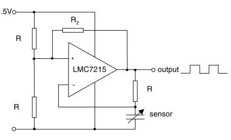
Figure 2.Square wave oscillator.
A material that fills the whole space between the two plates would make construction of the device both easier and therefore less expensive to manufacture. Metals do not deform sufficiently under low loads while polymers exhibit hysteresis under strain. However polymeric foams, made by dispersing a gas in a solid have the advantage of a choice of density and cell geometry. The gas-phase composition modifies the physical properties of the solid-phase plastic substrate. These foams can be manufactured with a low compression set (ASTM standard) giving them good stability and low hysteresis.
2.2. Capacitance
The sensor is based on the principle of estimating the capacitance between two conducting plates separated by an insulator. Now
C =ε0εrA
d (1)
whereCis the capacitance,ε0is the permittivity of free space,
εr the dielectric constant of the material in the gap, Ais the
area of the plates anddtheir separation. The capacitance is a function of the geometric configuration and dielectric constant. Linking the change in force applied across the plates to a change in eitherA,dorεrthrough a suitable elastomer creates
a sensor.
For ease of construction, the separation of the plates is used in which case the capacitance is an inverse function of the force. This follows from
F=k(d0−d) (2)
whereFis the force across the plates,kis a constant andd0is
the separation with zero force.
Combining equations (1) and (2) gives
C = ε0εrAk kd0−F
. (3)
Thus capacitance varies as the inverse function of force.
2.3. Square wave oscillator
A convenient method of converting a change in capacitance into a signal is to use a relaxation oscillator (figure 2).
Charging and discharging currents for the sensor flow through the resistor, R. The resistors, R1 form a potential
for a square wave output. Hysteresis for the comparator (LMC7215) is provided by the resistorR2.
The circuit oscillates with a frequency given by
f = 1
2C Rln[(R1+R2)/R2]
. (4)
Combining equations (3) and (4) (eliminatingC) shows that as the force increases the frequency decreases linearly as follows:
f = kd0−F
2Rε0εrAkln[(R1+R2)/R2]
. (5)
3. Experimental results
3.1. Polymer foams
Several polymer foams were studied to identify one with suitable mechanical and electrical properties. Samples were bonded between two brass shims (300 mm2) with cyanoacrylate. The whole assembly was bonded to a very high-density polycarbonate strip to provide a stable platform. Each sample was loaded to 8 N and unloaded with three replicates. Samples with a high hysteresis were rejected. The change in capacitance with applied load was measured using a standard 555 timer circuit and a supply voltage of 5 V.
Experimentally, the circuit (figure 2) was found to have a stable oscillation with a capacitance greater than 0.8 pF. To meet this requirement, the area, A, in equation (1) has to be more than 49 mm2(minimum diameter of 7.9 mm) for a relative
permittivity of 2.6 and a thickness of 1.4 mm.
3.2. Sensor
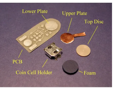
The circuit and sensor components are mounted on a printed circuit board (PCB), see figure 3. An 8 mm diameter piece of foam was bonded to the copper side of the upper plate made from Pyralux. On top of this, a shim formed the upper force plate made from PEEK (0.7 mm thick) which was bonded to the polyamide surface of the Pyralux. The foam was bonded to the lower plate. A ‘tang’ from the upper plate was rolled to form a loop and soldered to the PCB. The assembled device is shown in figure 4 together with an adult human small finger to illustrate the size of the sensor. The lead-lengths between the sensor and the inputs to the capacitor were made as short as possible to reduce the effects of adding stray capacitance to the sensor.
3.3. Load tests
Static forces were applied to the sensor using steel weights and the output frequency recorded using a frequency counter. Loads were applied incrementally to nearly 20 N and then unloaded. Three replicate experiments were carried out. Figure 5 shows the experimentally observed frequency against applied force.
3.4. Non-linear model
[image:3.595.307.536.82.260.2]Inspection of the characteristic (figure 5) demonstrates that while the frequency decreases with increase in force
[image:3.595.308.533.287.456.2]Figure 3.Components of the sensor.
Figure 4.Sensor and human finger.
20 15
10 5
0 9.5
9.0
8.5
8.0
7.5
7.0
frequency kHz
force N
Figure 5.Observed frequency against force.
(equation (5)) the relationship is non-linear. A monotonic model was fitted to the data of the form given below.
f =B1−B2FB3. (6)
[image:3.595.309.533.467.666.2]Table 2.Summary of parameter values and statistics.
Asymptotic 95% confidence interval Asymptotic
Parameter Estimate standard error Lower Upper
B1 9.046 9231 0.005 1306 9.036 79 9.057 06
B2 0.229 2875 0.003 7901 0.221 80 0.236 77
B3 0.660 4190 0.005 0015 0.650 54 0.670 30
[image:4.595.60.290.98.177.2]computer package SPSS gave anR-squared value of 0.998 77 demonstrating a very good fit to the model. Table 2 summarizes the parameter values.
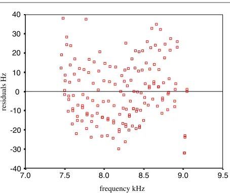
Figure 6 shows the residuals (Hz) against observed frequency.
3.5. Power and weight
The sensor supply current is 3µA at a voltage of 1.5 V. The device, complete with a coin-cell battery weighs 0.96 g.
4. Discussion
The sensor should be maintenance-free for a period of at least 6 months, at which point the battery could be replaced. For 6 months (4368 h), the circuit requires 13 mA h which can be supplied from a standard energizer 321 battery (14 mA h, 6.8 mm diameter and 1.65 mm thick). This is a significant advantage as the connections from the sensor to the controller are reduced from three to two wires (signal and ground). Future prosthetic hands will have large numbers of sensors so any savings with interconnections decreases the mass of a hand and improves its reliability. This design philosophy also anticipates that future sensors may be self powered, require minimal power consumption and be intelligent [9–11].
Three sensors could be mounted on a finger: one at the tip and one on each of the two other phalanges, making a total of 12 sensors for the four fingers. The thumb could have two while six could be sited on the palm. This arrangement has a mass of 20 g assuming a mass of 1 g per sensor including its interface circuits and interconnecting wires. To provide a sufficient number of sensors across the palmar surfaces represents 5% of the total mass (400 g) of a recent lightweight prosthesis [1]. Improvements in the sensor will reduce this value further, opening up the possibility of putting more sensors in a hand to improve functionality without a significant mass penalty.
A square wave output allows for a simple interface to a digital signal processor or microcontroller using a counter/timer to measure the output frequency. This technique has been successfully applied to accelerometers (Analogue Devices).
The absolute value of the slope of the characteristic decreases as the force increases (figure 5), forming a higher sensitivity for light grip forces, which is a desirable feature for this application. From equation (6) the slope is given by
ddFf=B2B3F(B3−1). (7)
The slope decreases with increasing force, as the parameterB3
is less than one.
9.5 9.0
8.5 8.0
7.5 7.0
40
30
20
10
0
-10
-20
-30
-40
residuals Hz
frequency kHz
Figure 6.Residuals against observed frequency.
Observed values of frequency were substituted into equation (6) to estimate the applied forces and these were subtracted from the actual applied forces. These absolute errors have a mean value of 0.82% and a standard deviation of 0.62%. The model for the sensor (equation (6)) demonstrates a potential accuracy of less than 1% which is a significant improvement compared to sensors like FSR. The force can be calculated by a microcontroller from the output frequency and the three parameters stored in memory.
It is possible that a local minimum can be found for the non-linear parameter estimation. The residuals show a fairly uniform distribution across the range of data points (figure 6), which is evidence that a global minimum has been found. Also the estimation was repeated a few times with different starting values and found to converge to the same parameter values.
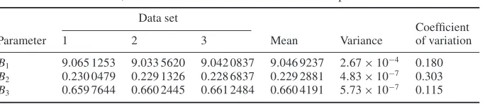
A test was made of how consistent the parameter fit is for different data sets. The data was divided into three sets and parameter estimates obtained (table 3).
The mean parameter values are only very slightly different from those estimated using all the data together (tables 2 and 3). The variances are small which demonstrates that the estimation is robust to noise, otherwise, if the parameter values were very different within the three data sets, the estimation would have been deemed to be ill conditioned. Parameter B2 has
the highest coefficient of variation (standard deviation as a percentage of the mean), followed byB1and thenB3.
Various effects contribute to the drift of frequency in a relaxation oscillator. Temperature fluctuation and power supply regulation are common to most circuits. An artificial hand operates over a temperature range from 0 to 40◦C so the addition of a small voltage regulator is required for the stable operation of the sensor. Stray and parasitic capacitance effects need careful consideration. A polymer is likely to have an insulation resistance in the range 104–108M µF, which is
higher than say the low leakage, found in tantalum capacitors
Table 3.Mean, variance and coefficient of variation for the parameter values.
Data set
Coefficient
Parameter 1 2 3 Mean Variance of variation
B1 9.065 1253 9.033 5620 9.042 0837 9.046 9237 2.67×10⁻⁴ 0.180
B2 0.230 0479 0.229 1326 0.228 6837 0.229 2881 4.83×10⁻⁷ 0.303
B3 0.659 7644 0.660 2445 0.661 2484 0.660 4191 5.73×10⁻⁷ 0.115
5. Conclusions
A very small, lightweight and low power sensor has been developed for use with artificial hands. It has a maximum sensitivity at low forces for griping lightweight objects. The sensor has been tested to a force of 20 N but has the potential to measure higher forces. A non-linear model accurately describes the relationship between the output frequency and applied force. It could be equally applicable to other sensors where polymer foam separates the plates of a capacitor. An integral small battery powers the sensor for up to six months. The output is a variable frequency square wave, which allows for a simple and serial interface to a digital signal processor or microcontroller.
Acknowledgments
The authors wish to acknowledge the contributions made to this project by C Adams and Y L Chong.
References
[1] Light C M and Chappell P H 2001 Development of a lightweight and adaptable multiple-axis hand prosthesis
Med. Eng. Phys.22679–84
[2] D’Amico A and Di Natale C 2001 A contribution on some basic definitions of sensors propertiesIEEE Sensors1
183–90
[3] Tise B 1988 A compact high resolution piezoresistive digital tactile sensorProc. IEEE Int. Conf. on Robotics and Automationvol 7 (Piscataway, NJ: IEEE) pp 760–4 [4] Kyberd P J and Chappell P H 1992 Characterisation of an
optical and acoustic touch and slip sensor for autonomous manipulationMeas. Sci. Technol.3969–75
[5] Kyberd P J and Chappell P H 1993 A force sensor for automatic manipulation based on the Hall effectMeas. Sci. Technol.4281–7
[6] Zhu F and Spronck J W 1992 A capacitive tactile sensor for shear and normal force measurementsSensors ActuatorsA
31115–20
[7] Wolffenbuttel M R and Regtien P P L 1990 Design considerations for a silicon capacitive tactile cellSensors ActuatorsA24187–90
[8] Despont M, Racine G A, Renaud P and de Rooij N F 1993 New design of micromachined capacitive force sensor
J. Micromech. Microeng.3239–42
[9] Brignell J and White N 1994Intelligent Sensor Systems
(Bristol: Institute of Physics Publishing)
[10] El-hami M, Glynne-Jones P, White N M, Hill M, Beeby S, James E, Brown A D and Ross J N 2001 Design and fabrication of a new vibration-based electromechanical power generatorSensors ActuatorsA92335–42 [11] Glynne-Jones P, Beeby S P and White N M 2001 Towards a