Design Evaluation and Material Optimization of a
Train Brake Shoe
V. Hemanth Kumar
1, P. Venkata Subbaiah
2, S. Ekramulvalli
3, K. Eswar Kumar
4, A. Satya Dinesh
51, 2 ,3, 4 IV B. Tech Students,5Assistant professor, Mechanical Engineering, Vignana Bharathi Institute of Technology, Proddatur, YSR
Kadapa Dist. JNTU Ananthapur
Abstract: The moving train having the kinetic energy. The train will be stopping by using brakes. When the brakes will apply on the train wheels the friction will be creates in between the wheels and brake shoe. This energy dissipated on surrounding in the form of heat. Friction is created heat; if the brake gets too hot they will cease to work because they cannot dissipate enough heat. The train brake is exposing the massive thermal traces throughout routing braking and extraordinary thermal traces throughout laborious braking. The major drawback in exciting train brake shoes is due to high thermal stresses, crakes create on the surface of brake shoe. The life of the brake shoe also decreased.
The aim of the project is to reduce the thermal stresses, crakes and increase the life of the brake shoe. Static, Modal analysis are to be done on the train brake. In static analysis, ultimate stress limit for the design is found. In modal analysis, mode shapes of the train brake for number of modes can be analysed. Presently the train brake material high carbon alloy we modified the material nickel chromium alloy, malleable cast iron. The modelling we are using SOLID WORKS and analysis is done using COSMOS.
Keywords: Train brake shoe, static analysis, High carbon steel, Malleable cast iron, Nickel chromium alloy, Modal analysis
I. INTRODUCTION
A Brake is a mechanical device which inhibits motion, slowing or stopping a moving object or preventing its motion. Most commonly brakes use friction between two surfaces pressed together to convert the kinetic energy of the moving object into heat though other methods of energy conversion may be employed.
A. Principles Of Braking System
Brakes are generally applied to rotating axles or wheels, but may also take other forms such as the surface of a moving fluid (flaps deployed into water or air). Some vehicles use a combination of braking mechanisms, such as drag racing cars with both wheel brakes and a parachute, or airplanes with both wheel brakes and drag flaps raised into the air during landing.
II. DIMENSIONS AND PROPERTIES
According to RDSO (Research and Development Standard (Organization), Lucknow, the following are standard designed values for Railway air brake system.
1) Brake cylinder diameter: 355.6 mm (14 inches) 2) Effective piston force of brake cylinder: 3.6 tons. 3) Number of brake cylinder per coach: 2.
4) Number of brake bogie levers per coach :4. 5) Mechanical efficiency of brake rigging: 0.9. 6) Brake rigging ratio: 0.9.
7) Number of brake shoes per one coach: 16
A. Suggest Modification
2D View of Brake Shoe B. Properties of Material
Property High carbon steel Malleable cast iron Nickel chromium alloy
Density (Kg/m3) 8260 7450 8195
Poisson’s ratio 0.32 0.27 0.32
Yield strength (MPa) 330 483 2300
Thermal conductivity (W/m.K) 30 22 17
Specific heat (J/Kg.K) 500 510 500
Ultimate tensile strength (MPa) 760 586 760
III. ANALYSIS
1) Static analysis for 1.653 ton 2) Applied pressure 0.55 N/mm2
A. High carbon steel: 1) Stress:
Name Type Minimum Maximum
Stress Von Mises Stresses 1.807e-008 N/mm2 (MPa)
Node: 679
4.980e+000 N/mm2 (MPa)
Node: 8377
2) Displacement
Name Type Minimum Maximum
Displacement Resultant Displacement 0.000e+000mm
Node: 275
[image:3.595.47.536.333.665.2]2.463e-003mm Node: 227
Fig.2 Displacement Results for High Carbon Steel
3) Strain
Name Type Minimum Maximum
Strain Equivalent Strain 1.489e-007
Element: 1662
2.198e-005 Element: 1649
Fig. 3 Strain Results for High Carbon Steel
B. Malleable Cast Iron: 1) Stress
Name Type Minimum Maximum
Stress Von Mises Stress 1.813e-008 N/mm2 (MPa)
Node: 7260
5.109e+000 N/mm2 (MPa)
Fig.4 Stress Results for Malleable Cast Iron
2) Displacement
Name Type Minimum Maximum
Displacement Resultant Displacement 0.000e+000 mm
Node: 275
2.585e-003 mm Node: 227
[image:4.595.81.527.310.483.2]
Fig.5 Displacement Results for Malleable Cast Iron
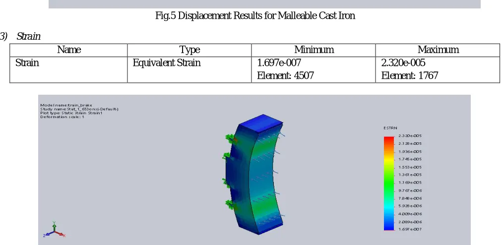
3) Strain
Name Type Minimum Maximum
Strain Equivalent Strain 1.697e-007
Element: 4507
2.320e-005 Element: 1767
[image:4.595.41.549.477.724.2]C. Nickel Chromium 1) Stress
Name Type Minimum Maximum
Stress Von Mises Stress 1.812e-008 N/mm2 (MPa)
Node: 7260
5.133e+000 N/mm2 (MPa)
Node: 8377
Fig.7 Stress Results for Nickel Chromium
2) Displacement
Name Type Minimum Maximum
Displacement Resultant Displacement 0.000e+000 mm Node: 275
2.003e-003 mm Node: 227
Fig.8 Displacement Results for Nickel Chromium
3) Strain
Name Type Minimum Maximum
Strain Equivalent Strain 1.233e-007
Element: 2486
1.801e-005 Element: 1767
D. High Carbon Steel 1) Stress
Name Type Minimum Maximum
Stress Von Mises Stress 2.399e-008 N/mm2 (MPa)
Node: 679
6.610e+000 N/mm2(MPa)
Node: 8377
Fig.10 Stress Results for High Carbon Steel
2) Displacement
Name Type Minimum Maximum
Displacement Resultant Displacement 0.000e+000 mm
Node: 275
3.270e-003 mm Node: 227
Fig.11 Displacement Results for High Carbon Steel
3) Strain
Name Type Minimum Maximum
Strain Resultant Strain 1.976e-007
Element: 1662
2.917e-005 Element: 1649
E. Malleable Cast Iron 1) Stress
Name Type Minimum Maximum
Stress Von Mises Stress 2.406e-008 N/mm2 (MPa)
Node: 7260
6.782e+000 N/mm2 (MPa)
Node: 8377
Fig.13 Maximum Stress Results for Malleable Cast Iron
2) Displacement
Name Type Minimum Maximum
Displacement Resultant Displacement 0.000e+000 mm
Node: 275
3.431e-003 mm Node: 227
Fig.14 Displacement Results for Malleable Cast Iron
3) Strain
Name Type Minimum Maximum
Strain Resultant Strain 2.252e-007
Element: 4507
3.080e-005 Element: 1767
F. Nickel Chromium 1) Stress
Name Type Minimum Maximum
Stress Von Mises Stress 2.405e-008 N/mm2 (MPa)
Node: 7260
6.813e+000 N/mm2 (MPa) Node: 8377
Fig.16 Stress Results for Nickel Chromium
2) Displacement
Name Type Minimum Maximum
Displacement Resultant Displacement 0.000e+000mm
Node: 275
2.658e-003mm Node: 227
Fig.17 Displacement Results for Nickel Chromium
3) Strain
Name Type Minimum Maximum
Strain Resultant Strain 1.637e-007
Element: 2486
2.390e-005 Element: 1767
G. Modal Analysis 1) High Carbon Steel
Name Type Minimum Maximum
Amplitude 1 AMPRES: Resultant Amplitude Plot for
Mode Shape: 1(Value = 3933.73 Hz)
0.000e+000 Node: 275
8.027e-001 Node: 224
Fig.19 Amplitude 1 Results for High Carbon Steel
2) Malleable Cast Iron
Name Type Minimum Maximum
Amplitude 1 AMPRES: Resultant Amplitude Plot
for Mode Shape: 1(Value = 3970.78 Hz)
0.000e+000 Node: 275
8.481e-001 Node: 224
Fig.20 Amplitude 1 Results for Malleable Cast Iron 3) Nickel Chromium
Name Type Minimum Maximum
Amplitude 1 AMPRES: Resultant Amplitude Plot
for Mode Shape: 1(Value = 4144.7 Hz)
0.000e+000 Node: 275
Fig.21 Amplitude 1 Results for Nickel Chromium
IV. RESULTS TABLE
A. For load 1.653-ton pressure 0.55 N/mm2
S.No Material Stress (N/mm2) Displacement (mm) Strain
1. High Carbon Steel 4.9805 2.463e-3 2.198e-5
2. Malleable Cast Iron 5.109 2.585e-3 2.320e-5
3. Nickel Chromium 5.133 2.003e-3 1.801e-5
B. For load 2.187-ton pressure 0.73 N/mm2
S.No Material Stress (N/mm2) Displacement (mm) Strain
1. High Carbon Steel 6.610 3.270e-3 2.917e-5
2. Malleable Cast Iron 6.782 3.431e-3 3.080e-5
3. Nickel Chromium 6.813 2.658e-3 2.390e-5
S.No Material Amplitude 1
(Hz) Amplitude 2 (Hz) Amplitude 3 (Hz) Amplitude 4 (Hz) Amplitude 5 (Hz)
1. High Carbon Steel 0.8027 0.8055 0.8001 0.8147 0.7663
2. Malleable Cast Iron 0.8481 0.8498 0.8278 0.8422 0.7821
3. Nickel Chromium 0.7834 0.7848 0.7607 0.7738 0.7168
V. CONCLUSION
In this project we are calculated the von mises stress, displacement, strain for the High carbon steel, Malleable cast iron and Nickel chromium. Thus we are prepared the 3D models by solid works software. Presently using material for manufacturing of train brake shoe is High carbon steel we modify that material to Malleable cast iron and Nickel chromium. By the comparing the static results the Malleable cast iron has little more than the High carbon steel and less than the Nickel chromium materials. By comparing the modal analysis from the above tables we got less frequency for Nickel Chromium than other two materials, the malleable cast iron was more frequency than other materials and possess high strength Finally, we are concluding that present material high carbon steel will be replacing with the Malleable cast iron is good for future.
VI. FUTURE SCOPE
REFERENCES
[1] Dr. D.S. Deshmukh & Jha Shankar Madanmohan “Design Evaluation and Material Optimization of a Train brake” in International Journal of Research Studies in Science, Engineering and Technology [IJRSSETT] Volume 1, Issue 2, May 2014.
[2] Chintha Sreedhar, P.Ghiribabu, P.Umamahesh “FEM analysis on locomotive train brake for improved efficiency by using CATIA and ANSYS work bench”, International Research Journal of Engineering and Technology (IRJET) – Volume 02 Issue:08 NOV-2015.
[3] Ambikaprasad.O. Chaubey, Prof.Abhijeet.A.Raut “Failure Analysis of Brake Shoe in Indian Railway Wagon” IPASJ International Journal of Mechanical Engineering (IIJME) Volume 3, Issue 12, December 2015.
[4] Shubham Wanve, Akash Malode, Nikhil Ghonmode “An Analysis for Improving of Train Brake Pad by Using CAD and CAE Software” International Research Journal of Engineering and Technology (IRJET) Volume 4, Issue 10, Oct 2017.