Abstract— The most commonly used aerospace titanium alloy, Ti6Al4V, was deposited on Ti6Al4V plate of dimension 72 x 72 x5mm. The laser power of 3 kW, powder flow rate of 1.44 g/min and gas flow rate of 4 l/min were used throughout the deposition process. The transverse/ scanning speed was varied between 0.005 to 0.095 m/sec according to established result of the preliminary study that produces full dense and pore free deposits. The mass of the deposited powder was obtained by weight the substrate before deposition and reweighing after deposition. The substrate and the deposits were thoroughly cleaned using wire brush and acetone to remove unmelted powder particles from the surface of the substrate and the deposit. The height and width of the deposits were measured with Venier Caliper and the material efficiencies were determined using developed equations. The effect of the scanning speed on the material efficiency and deposit height were extensively studied and the results showed that for the set of processing parameter used in this study the optimum scanning speed is approximately 0.045 m/sec.
Index Terms—Additive manufacturing, Laser metal deposition, Material efficiency, Titanium alloy
I. INTRODUCTION
ASER Metal Deposition (LMD) is an additive manufacturing method that produces component by building it layer by layer directly from three dimensional CAD model [1]. Manufacturing near-net shape parts by them building layer by layer offer great advantage that includes: time saving, weight saving and overall cost saving when compared with the traditional manufacturing methods [2, 3]. A component that needs to be broken down into various parts and later assembled in traditional manufacturing process can be produced in one single piece using LMD. This will eliminate various steps of joining and
Manuscript received July 27, 2012; revised October 8, 2012. This work was supported by the Rental Pool Grant of the National Laser Centre -Council of Scientific and Industrial Research (NLC-CSIR), Pretoria, South Africa and The Schlumberger Foundation Faculty for the Future (FFTF).
Ms. Rasheedat M. Mahamood is a doctorate Student in the Department of Mechanical Engineering Science, University of Johannesburg, Auckland Park Campus, Johannesburg, South Africa, 2006. (e-mail: [email protected] or [email protected] )
Dr Esther T. Akinlabi is a Senior Lecturer in the Department of Mechanical Engineering Science, University of Johannesburg, Auckland Park Campus, Johannesburg, South Africa, 2006. (Phone: +2711-559-2137; email: [email protected]).
Prof Mukul Shukla is an Associate Professor in the Department of Mechanical Engineering Science, University of Johannesburg, Auckland Park Campus, Johannesburg, South Africa, 2006. (e-mail: [email protected]).
Prof Sisa Pityana is a Research Scientist in the National Laser Centre of Council for Scientific and Industrial Research (CSIR), Pretoria, South Africa. (E-mail: [email protected].)
fastening required to assemble the parts in traditional technique thereby reducing manufacturing time and overall cost of the part. Most importantly, for automobile and aerospace industry is the weight saving achieved through the elimination of extra weight coming from bolt, nut, rivets etc. used during assembly that is of great importance. It does not only reduce cost of producing the component but it will also reduce fuel consumption. Laser metal deposition process also offer an excellent advantage over other additive manufacturing techniques in that it can be used to repair high valued component parts which were prohibitive or difficult to repair and are discarded in the past. This is one of the reasons why LMD is an important research area [4-6] and also this technology is very important for manufacturing and repair of aerospace parts.
Ti6Al4V is the most commonly produced titanium alloy and also the most commonly used titanium alloy in the aerospace industry [7]. Ti6Al4V offer excellent properties [8, 9] that make them most sorted material in aerospace, chemical, defense, energy industry etc. The use of titanium is still limited to high valued components because of the high cost of the material and difficulty in machining. The use of laser metal deposition process to produce titanium alloy parts is an excellent alternative to traditional techniques. Additive manufacturing is generally cost effective to produce parts because the unspent materials can be reused. The reuse of titanium alloy is impossible because of the high affinity of the metal to oxygen pickup at high temperature [10]; this makes the study of material efficiency
an important one because of the high cost of the material. In this study, effect of laser transverse speed or scanning
speed on the deposit height and material efficiency is investigated. The result of this study will provide an informed decision on the choice of processing parameter that maximizes the use of material while maintaining metallurgical integrity and minimum dilution.
II. MATERIALS AND METHODS
The materials and methods are subdivided into four sections namely: materials and equipment, laser metal deposition process, material efficiency determination and macrostructure and microstructure examinations.
A. Materials and equipment
Laser metal deposition process was achieved with 4.4 kW fiber delivered Nd: YAG laser with coaxial nozzles carried and controlled by Kuka robot available at CSIR national laser center. The powder was delivered through argon gas. 5mm thick Ti6Al4V plate with area 72 x 72mm of 99.6%
The Role of Transverse Speed on Deposition
Height and Material Efficiency in Laser
Deposited Titanium Alloy
Rasheedat M. Mahamood, Esther T. Akinlabi, Mukul Shukla and Sisa Pityana
schematic diagram of the laser metal deposition process is shown on Figure 1. The Ti6Al4V powder used in this study has a particle size range between 150-200 µm. Prior to the deposition process the substrate was sandblasted, degreased with acetone and dried.
Fig. 1: Schematics of Laser Metal Deposition Process B. Laser Metal Deposition Process
[image:2.595.51.288.147.269.2]To achieve the deposition processing parameter used in this study, a set of preliminary experiments was conducted to establish process window in which fully dense deposition without porosity and good metallurgical integrity was obtained. The laser power of 3 kW, powder flow rate of 1.44g/min and gas flow rate of 4 l/min were maintained throughout the deposition process. The scanning speed of whose effect was investigated was varied between 0.005m/sec and 0.095m/sec. a total of ten (10) deposits were made on the substrates of single track 60mm long each using the processing parameters in Table 1.
Table 1. Processing parameter Sample
Label Laser power (kw) Scanning speed (m/sec) Powder flow rate (g/min) Gas flow rate (l/min)
A 3.0 0.005 1.44 4
B 3.0 0.015 1.44 4
C 3.0 0.025 1.44 4
D 3.0 0.035 1.44 4
E 3.0 0.045 1.44 4
F 3.0 0.055 1.44 4
G 3.0 0.065 1.44 4
H 3.0 0.075 1.44 4
I 3.0 0.085 1.44 4
J 3.0 0.095 1.44 4
C. Material Efficiency Determination
Before the start of deposition, the mass of the substrate was taken using digital balance. After deposition of each track, the deposit and the substrate were cleaned with wire brush and acetone to remove all unmelted powder particles on the substrate and the deposit, and then reweighed to know the mass of actual powder deposited. The height and the width (see Figure 2.) of the deposit was taken using Vernier Caliper. The material efficiency was determined using the following equations [11].
0 S S
P
m
m
m
f
f
---(1)
D
S
L
T
S
/
andT
D
L
/
S
S--- (2)
60
0
FR
D
P
P
T
m
--- (3)
/
100
0
m
Pm
pf
--- (4) Where: f Pm
(g) is the mass of powder deposited. 0S
m
(g) is the mass of the substrate before deposition process.f
S
m
(g) is the mass of substrate after deposition. SS (m/sec) is the scanning speed. TD (sec) is the time takenfor the deposition. L(mm) is the length of each track which is 60 mm.
0 P
m
(g/sec) is the mass of powder delivered during deposition. PFR is the powder flow rate in g/min. μis the powder efficiency.
D. Macrostructure and Microstructure Examinations The samples were laterally sectioned and prepared for optical microscopy using standard metallurgical techniques. The macrostructure and microstructure were studied to know the metallurgical integrity of the deposits.
III. RESULTS AND DISCUSSION
A. Results
[image:2.595.327.501.273.365.2]The morphology of the powder used is shown in Figure 3 as viewed under optical microscope and the particle size distribution analysis is shown in Figure 4.
Figure 3: Morphology of Ti6Al4V powder
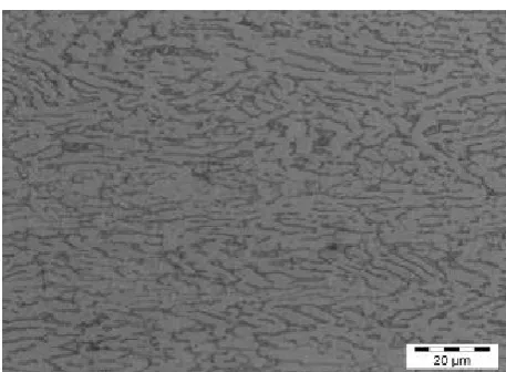
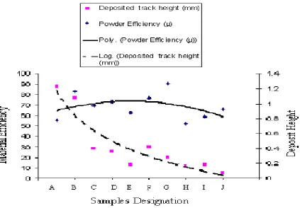
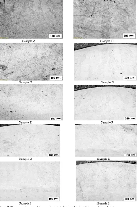
[image:2.595.303.534.545.768.2]The microstructure of the substrate is shown in Figure 5. The material efficiencies for each of the deposits at various processing parameters (see Table 1) were determined using equations (1) to (4). The processing parameters, the measured height and width of the deposits and the calculated efficiencies are presented in Table 2. The plots of the material efficiency and the deposition height against the scanning speed (see Figure 2) is shown in Figure 6, the curves are fitted using appropriate curve fitting tools in Microsoft Excel. Figure 7 shows the Macrostructure of the deposit and the substrate while Figure 8 shows the microstructure of the fusion zone to study the metallurgical integrity of the deposit.
Figure 5: Microstructure of the substrate
B. Discussion of Results
It is seen from the graph that the deposition height decreases as the scanning speed increases, this is as a result of less powder being delivered as the deposition time decreases. Also the time for the laser material interaction decreases as the scanning speed increases. The material efficiency on the other hand increases initially and then decreases with the maximum efficiency at scanning speed of 0.045m/sec. this can be attributed to the fact that as scanning speed increases initially more powders are melted effectively until it reaches maximum at the scanning speed of 0.045m/sec and then as the scanning speed increases
further there is less time to melt the powder. The optimum material efficiency is around the scanning speed of about 0.015m/sec.
The macrostructures shown in Figure 7 show that the deposits are sound and the columnar prior beta grains are seen in all the samples with no visible pours. To further confirm the metallurgical integrity of the deposits, the microstructures shown in Figure 8 further confirm there is no porosity and all the deposits are of good metallurgical bonding. Grains in the fusion zone are continuous with the basket weave seen in all the samples which confirms that the materials at this region are fully melted which is consistent with the literature [12, 13].
IV. CONCLUSION
Ti6Al4V powder was deposited on Ti6Al4V substrate at varying scanning speed while maintaining laser power, powder flow rate and gas flow rate at constant values of 3 kW, 1.44 g/min and 4 l/min respectively. The range of scanning speed (0.005 to 0.095 m/sec) used was selected based on the result of preliminary experiment that establishes processing window of fully dense deposit without porosity and with good metallurgical bonding. The effect of these scanning speeds on the material efficiency, deposit height, and width were studied extensively. The study reveals that the optimum scanning speed in this study is approximately 0.045 m/sec. this scanning speed will keep the material utilization on the high side while minimizing the dilution.
REFERENCES
[1] Toyserkani, E. and Khajepour, A. A mechatronics approach to laser powder deposition process. Mechatronics, 2006, 16(10), 631–641. [2] Irwin, Pa., Rapid Growth of Additive Manufacturing Disrupts
Traditional Manufacturing Process, Press release, 2012, available at http://exone.com/sites/default/files/media/ExOne_Launch
_Press_Release.pdf, accessed online on 20th July 2012.
[3] T. Campbell, C. Williams, O. Ivanova, B. Garrett, Could 3D Printing Change the World? Technologies, Potential, and Implications of Additive Manufacturing, strategic foresight report, 2011, Available at http://www.acus.org/files/publication_pdfs/403/10171
1_ACUS_3DPrinting.PDF, accessed online on 21st July 2012. [4] A J Pinkerton, W Wang, and L Li, Component repair using laser
direct metal deposition, Proc. IMechE Part B: J. Engineering Manufacture, 2008, vol. 222, pp. 827-836.
Table 2. Results showing track heights, widths and material efficiency
Sample Designat ion Laser Power (kW) Scanning Speed (m/Sec) Powder Flow Rate (g/min) Gas Flow Rate (l/min) 0 P
m
(g/sec) f Pm
(g/sec) Deposite d Track Width (mm) Deposite d Track Height (mm)Powder Efficienc y µ (%)
A 3.0 0.005 1.44 4 0.288 0.16 5.9 1.23 55.56
B 3.0 0.015 1.44 4 0.096 0.08 4.3 1.07 83.33
C 3.0 0.025 1.44 4 0.058 0.04 3.1 0.4 69.44
D 3.0 0.035 1.44 4 0.047 0.03 2.9 0.36 72.92
E 3.0 0.045 1.44 4 0.032 0.02 3.4 0.18 62.50
F 3.0 0.055 1.44 4 0.026 0.02 3.0 0.42 76.39
G 3.0 0.065 1.44 4 0.022 0.02 2.56 0.28 90.28
H 3.0 0.075 1.44 4 0.019 0.01 2.56 0.16 52.08
I 3.0 0.085 1.44 4 0.017 0.01 2.52 0.18 59.03
[image:3.595.46.275.427.595.2][5] TWI, Laser Metal Deposition available at
http://www.twi.co.uk/technologies/welding-coating-and-material-processing/additive-manufacture/laser-metal-deposition/ accessed online on 24th July 2012.
[6] RPM and associates, Laser Deposition Technology (LDT), available at
http://www.rpmandassociates.com/LaserDepositionTechnology.aspx, accessed online on 24th July 2012.
[7] M. Esmailian, M. Mehrvar, Investigation of the effect of AL2O3 powder in Electro Discharge Machining for Titanium alloys, ICME, vol. 9, (2007), pp. 549-557.
[8] Cai Z, Nakajima H, Woldu M, Berglund A, Bergman M, Okabe T. In vitro corrosion resistance of titanium made using different fabrication methods. Biomaterials. 1999; 20(2):183-190.
[9] Wang ZM, Ezugwu EO. Titanium Alloys and Their Machinability a Review. Journal of Materials Processing Technology 1997, pp. 68:262.
[10] Qu J, Blau PJ, Watkins TR, Cavin OB, Kulkarni NS. Frction and wear of titanium alloys sliding against metal, polymer, and ceramic counterfaces. Wear 2005; 258:1348-1356.
[11] Mahamood M. R., Akinlabi E.T, Shukla M. and Pityana S., Effect of Laser Power on Material Efficiency, Layer Height and Width of Laser Metal Deposited Ti6Al4V, WCECS 2012, Submitted.
[12] Y. Lu, H.B. Tang, Y.L. Fang, D. Liu, H.M. Wang, Microstructure evolution of sub-critical annealed laser deposited Ti–6Al–4V alloy, Materials and Design, vol. 37, 2012, pp. 56–63.
[image:4.595.75.499.58.352.2][13] E. Brandl, V. Michailov, B. Viehweger, C. Leyens, Deposition of Ti– 6Al–4V using laser and wire, part I: Microstructural properties of single beads, Surface & Coatings Technology, vol. 206, 2011, pp. 1120–1129.