Copyright © 2013 IJECCE, All right reserved 1717
International Journal of Electronics Communication and Computer Engineering Volume 4, Issue 6, ISSN (Online): 2249–071X, ISSN (Print): 2278–4209
Partial H-Plane Band-Pass Waveguide Filter Using
Compact Resonators
M. Hajnorouzi
The University of Guilan Email: [email protected]H. Ghorbaninejad
The University of Guilan Email: [email protected]Abstract–In this paper partial band-pass waveguide filter using compact resonators are presented which is implemented in partial H-plane waveguide. Partial H-plane band-pass filters compared with E-plane band-pass filters, in the same frequency range, have one quarter cross section size. Partial H-plane band-pass waveguide filter with compact resonators has less longitudinally length relative to the conventional partial H-plane filters. Compact resonators in partial H-plane waveguides reduce both the cross section size and the total length of filter, in the same frequency range while compared with conventional partial H-plane filters. In the design procedure, the shape of resonators is determined by fitting the characteristic (transfer function) of a desired resonator to that obtained from an equivalent circuit model. The design process is based on optimization using an electromagnetic simulation to take the effect of higher order modes (evanescent mode). The usefulness of the proposed partial H-plane band-pass filter and its performance are verified by designing and simulating two filters.
Keywords – Partial H-plane Waveguide, E-Plane Waveguide Band-Pass Filters, Half-wavelength Resonator, Quarter Wave-Length Resonator, Compact Resonator.
I. I
NTRODUCTIONMicrowave filters are important components in communication systems which can be used in many devices such as multiplexers and satellite communications. The fast development of RF technology requires having components with compact sizes. Conventionally, microwave filters use inductive elements such as irises, rods, diaphragms and posts with transmission line resonators which are realized with half wave length hollow or dielectric filled waveguides [1-4]. The dielectric resonator (DR) filters is introduced to compact overall size of band-pass filters [5-8]. For the low-cost property consideration, E-plane filters [9] and H-plane filters [10] are widely used in the design of microwave filters but they have the disadvantage of large sizes especially at low frequencies. The cross section of a partially H-plane filter is one quarter of the cross section of a conventional waveguide while the dispersion characteristic of the two structures are the same for first and second mode, therefore using partial H-plane waveguide will reduce the cross sectional size of filter to one quarter compared with conventional waveguides [11]. But the resonators of the filters are realized by half-wavelength or quarter wavelength waveguide sections that does not reduce the longitudinally size of filters compared with conventional E-plane filters. For further reduction of the longitudinally size of such filters three types of partial H-plane filters using half wavelength or quarter wavelength resonators is designed by which in the best case, the length of filter is
shorted to that of conventional E-plane filter about % 29.2 [11].
In this paper partial H-plane band-pass waveguide filter using compact resonators are designed whose longitudinally length is considerably shorter than that of half wavelength or quarter wavelength waveguide section resonators which is used in the designed partial H-plane filters. Replacing existing half wavelength or quarter wavelength waveguide sections by this new type resonator reduce the longitudinally size while its cross section is one quarter of E-plane waveguide band-pass filter and both have the same frequency responses. Partial H-plane band-pass waveguide filter with compact resonators has less longitudinally length relative to the designed partial H-plane filters and in the same time its cross section size is one quarter of conventional E-plane filters which leads to further size reduction in the filter structure. The shape of resonators is determined by fitting the characteristic (transfer function) of a desired resonator to that obtained from an equivalent circuit model.
II. P
ARTIALH-P
LANEW
AVEGUIDE AND ITSE-P
LANEC
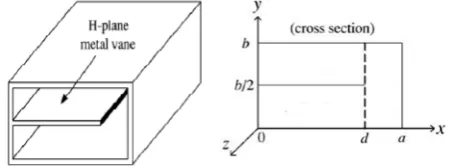
OUNTERPARTFig. 1 shows the structure and geometry of a partial plane waveguide and its cross section view. Partial H-plane waveguide is a conventional rectangular waveguide in which a partially H-plane metal vane is located. The cross section of partially H-plane filter is one quarter of the rectangular waveguide. By transversally folding a rectangular waveguide one can obtain a partially H-plane wave guide. In [11] has been shown that the dispersion characteristics of partial H-plane waveguide of size a=23.8 mm, b=12mm, d=20.2mm and rectangular waveguide of size a=47.55, b= 22.15mm in the frequency range of 4.5-5.5 GHz and for dominant and second mode are the same. The cross section of partial H-plane waveguide is one quarter of conventional waveguide while its frequency characteristic is the same.
Fig.1. Partial H-plane Waveguide and Its cross section [11]
Copyright © 2013 IJECCE, All right reserved 1717
International Journal of Electronics Communication and Computer Engineering Volume 4, Issue 6, ISSN (Online): 2249–071X, ISSN (Print): 2278–4209
Partial H-Plane Band-Pass Waveguide Filter Using
Compact Resonators
M. Hajnorouzi
The University of Guilan Email: [email protected]H. Ghorbaninejad
The University of Guilan Email: [email protected]Abstract–In this paper partial band-pass waveguide filter using compact resonators are presented which is implemented in partial H-plane waveguide. Partial H-plane band-pass filters compared with E-plane band-pass filters, in the same frequency range, have one quarter cross section size. Partial H-plane band-pass waveguide filter with compact resonators has less longitudinally length relative to the conventional partial H-plane filters. Compact resonators in partial H-plane waveguides reduce both the cross section size and the total length of filter, in the same frequency range while compared with conventional partial H-plane filters. In the design procedure, the shape of resonators is determined by fitting the characteristic (transfer function) of a desired resonator to that obtained from an equivalent circuit model. The design process is based on optimization using an electromagnetic simulation to take the effect of higher order modes (evanescent mode). The usefulness of the proposed partial H-plane band-pass filter and its performance are verified by designing and simulating two filters.
Keywords – Partial H-plane Waveguide, E-Plane Waveguide Band-Pass Filters, Half-wavelength Resonator, Quarter Wave-Length Resonator, Compact Resonator.
I. I
NTRODUCTIONMicrowave filters are important components in communication systems which can be used in many devices such as multiplexers and satellite communications. The fast development of RF technology requires having components with compact sizes. Conventionally, microwave filters use inductive elements such as irises, rods, diaphragms and posts with transmission line resonators which are realized with half wave length hollow or dielectric filled waveguides [1-4]. The dielectric resonator (DR) filters is introduced to compact overall size of band-pass filters [5-8]. For the low-cost property consideration, E-plane filters [9] and H-plane filters [10] are widely used in the design of microwave filters but they have the disadvantage of large sizes especially at low frequencies. The cross section of a partially H-plane filter is one quarter of the cross section of a conventional waveguide while the dispersion characteristic of the two structures are the same for first and second mode, therefore using partial H-plane waveguide will reduce the cross sectional size of filter to one quarter compared with conventional waveguides [11]. But the resonators of the filters are realized by half-wavelength or quarter wavelength waveguide sections that does not reduce the longitudinally size of filters compared with conventional E-plane filters. For further reduction of the longitudinally size of such filters three types of partial H-plane filters using half wavelength or quarter wavelength resonators is designed by which in the best case, the length of filter is
shorted to that of conventional E-plane filter about % 29.2 [11].
In this paper partial H-plane band-pass waveguide filter using compact resonators are designed whose longitudinally length is considerably shorter than that of half wavelength or quarter wavelength waveguide section resonators which is used in the designed partial H-plane filters. Replacing existing half wavelength or quarter wavelength waveguide sections by this new type resonator reduce the longitudinally size while its cross section is one quarter of E-plane waveguide band-pass filter and both have the same frequency responses. Partial H-plane band-pass waveguide filter with compact resonators has less longitudinally length relative to the designed partial H-plane filters and in the same time its cross section size is one quarter of conventional E-plane filters which leads to further size reduction in the filter structure. The shape of resonators is determined by fitting the characteristic (transfer function) of a desired resonator to that obtained from an equivalent circuit model.
II. P
ARTIALH-P
LANEW
AVEGUIDE AND ITSE-P
LANEC
OUNTERPARTFig. 1 shows the structure and geometry of a partial plane waveguide and its cross section view. Partial H-plane waveguide is a conventional rectangular waveguide in which a partially H-plane metal vane is located. The cross section of partially H-plane filter is one quarter of the rectangular waveguide. By transversally folding a rectangular waveguide one can obtain a partially H-plane wave guide. In [11] has been shown that the dispersion characteristics of partial H-plane waveguide of size a=23.8 mm, b=12mm, d=20.2mm and rectangular waveguide of size a=47.55, b= 22.15mm in the frequency range of 4.5-5.5 GHz and for dominant and second mode are the same. The cross section of partial H-plane waveguide is one quarter of conventional waveguide while its frequency characteristic is the same.
Copyright © 2013 IJECCE, All right reserved
III. P
ARTIALH-P
LANEF
ILTERFig.2 shows the structure and geometry of a partial H-plane band-pass filter with half-wavelength or quarter wavelength resonator sections and proposed partial H-plane waveguide band-pass filter with compact resonators. H-plane band-pass filter with half-wavelength or quarter wavelength resonator sections [11] is made of evanescent waveguide sections and half wavelength waveguide sections which are placed between them. In this structure the evanescent waveguide sections act as impedance invertors and half wavelength or quarter wavelength waveguide sections act as resonators. The partial H-plane waveguide band pass filter with compact resonators is made of resonator sections and waveguide sections. In the proposed structures waveguide sections act as admittance invertors. In proposed designed method the length of each resonator is considerably less than half wavelength waveguide section or even quarter wave length waveguide sections resonators which leads to longitudinally reduced size filters compared with partial H-plane band-pass filter with half-wavelength or quarter wavelength resonator sections. The method of design of this partial H-plane waveguide band-pass filter is straightforward which is extensively explained in [11] which is based on optimization using an electromagnetic simulation. The later section dedicated to the design method of compact resonators using high frequency simulation software and circuit theory model.
(a)
(b)
Fig.2. (a) Three view and top view Structure of proposed partial H-plane band-pass filter with compact resonators (b) Three view and top view structure of partial H-plane band-pass filter with half-wavelength or quarter wavelength resonator sections [11]
IV. S
TRUCTUREA
NDG
EOMETRY OFP
ROPOSEDR
ESONATORS ANDD
ESIGNM
ETHODFig.3 shows top view of a proposed partial H-plane resonator. The resonator is located within a partial H-plane waveguide. The principle of partial H-plane resonator design is based on optimization using HFSS software. To design a waveguide band pass filter, one can calculate an LC equivalent circuit model. Figure 4 illustrated a band pass filter consisting of N parallel resonator and N+1 admittance invertors. The values of admittance invertors and parallel resonators can be calculated according to the desired filter specifications such as filter type, center frequency and the bandwidth of filter. This circuit model can be realized using N shunt resonators and N+1 quarter wavelength transmission line sections. In the conventional design methods the length of resonator units is about half wavelength waveguide sections. To obtain the geometry of proposed resonators, the dimension of resonators, are optimized using an electromagnetic simulator (HFSS) so that the frequency response of resonator can be fitted to that of LC circuit model resonators. In the optimization process the dimension of resonators are determined so that the S-parameters of electromagnetic simulator fit to that of LC circuit model, which are evaluated in frequency samples. In this designs 101 frequency samples in the range of frequency domain, 4.5-5.5 GHz, is considered.
Fig.3. Geometry of partial H-plane resonator
Fig.4. Typical band pass filters using parallel resonator
V. D
ESIGNEDE
XAMPLES ANDR
ESULTSIn this section two proposed partial H-plane Filter utilizing a rectangular waveguide with a=23.8 mm and b= 12 mm. The first design is a for 5-order equal ripple chebyshev filter with center frequency f0 = 5 GHz, the relative bandwidth 5 percent and equal ripples 0.01 dB is designed. In this design thickness of metal vane has not been considered.
Copyright © 2013 IJECCE, All right reserved
III. P
ARTIALH-P
LANEF
ILTERFig.2 shows the structure and geometry of a partial H-plane band-pass filter with half-wavelength or quarter wavelength resonator sections and proposed partial H-plane waveguide band-pass filter with compact resonators. H-plane band-pass filter with half-wavelength or quarter wavelength resonator sections [11] is made of evanescent waveguide sections and half wavelength waveguide sections which are placed between them. In this structure the evanescent waveguide sections act as impedance invertors and half wavelength or quarter wavelength waveguide sections act as resonators. The partial H-plane waveguide band pass filter with compact resonators is made of resonator sections and waveguide sections. In the proposed structures waveguide sections act as admittance invertors. In proposed designed method the length of each resonator is considerably less than half wavelength waveguide section or even quarter wave length waveguide sections resonators which leads to longitudinally reduced size filters compared with partial H-plane band-pass filter with half-wavelength or quarter wavelength resonator sections. The method of design of this partial H-plane waveguide band-pass filter is straightforward which is extensively explained in [11] which is based on optimization using an electromagnetic simulation. The later section dedicated to the design method of compact resonators using high frequency simulation software and circuit theory model.
(a)
(b)
Fig.2. (a) Three view and top view Structure of proposed partial H-plane band-pass filter with compact resonators (b) Three view and top view structure of partial H-plane band-pass filter with half-wavelength or quarter wavelength resonator sections [11]
IV. S
TRUCTUREA
NDG
EOMETRY OFP
ROPOSEDR
ESONATORS ANDD
ESIGNM
ETHODFig.3 shows top view of a proposed partial H-plane resonator. The resonator is located within a partial H-plane waveguide. The principle of partial H-plane resonator design is based on optimization using HFSS software. To design a waveguide band pass filter, one can calculate an LC equivalent circuit model. Figure 4 illustrated a band pass filter consisting of N parallel resonator and N+1 admittance invertors. The values of admittance invertors and parallel resonators can be calculated according to the desired filter specifications such as filter type, center frequency and the bandwidth of filter. This circuit model can be realized using N shunt resonators and N+1 quarter wavelength transmission line sections. In the conventional design methods the length of resonator units is about half wavelength waveguide sections. To obtain the geometry of proposed resonators, the dimension of resonators, are optimized using an electromagnetic simulator (HFSS) so that the frequency response of resonator can be fitted to that of LC circuit model resonators. In the optimization process the dimension of resonators are determined so that the S-parameters of electromagnetic simulator fit to that of LC circuit model, which are evaluated in frequency samples. In this designs 101 frequency samples in the range of frequency domain, 4.5-5.5 GHz, is considered.
Fig.3. Geometry of partial H-plane resonator
Fig.4. Typical band pass filters using parallel resonator
V. D
ESIGNEDE
XAMPLES ANDR
ESULTSCopyright © 2013 IJECCE, All right reserved 1719
International Journal of Electronics Communication and Computer Engineering Volume 4, Issue 6, ISSN (Online): 2249–071X, ISSN (Print): 2278–4209
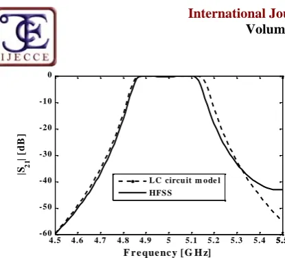
Optimization rang is 4.5-5.5 GHz and frequency sample steps is 10 MHz and it is assumed 15 frequency samples in pass-band and 43 frequency samples in each stop bands. Fig. 5 shows frequency responses of circuit model and that of designed partial H-plane resonators. By symmetry conditions resonators 1 and 2 are the same as resonators 5 and 4 respectively. Fig. 6 shows frequency responses of circuit model and that of designed partial H-plane filter. There is a good agreement between the frequency characteristics of desired filter and that of Designed filter over the frequency range.
(a)
(b)
(c)
Fig.5. Frequency responses of circuit model and that of designed partial H-plane resonators with zero metal vane thickness (a) resonators 1 and 5 (b) Resonators 2 and 4 (c) resonator 3
Fig.6. Frequency response of circuit model and that of designed partial H-plane filter with zero metal vane
thickness
(a)
(b)
(c)
Fig.7. Frequency responses of circuit model and that of designed partial H-plane resonators with 0.1 mm metal vane thickness (a) resonators 1 and 5 (b) Resonators 2 and 4 (c) resonator 3
4.5
4.7
4.9
5.1
5.3
5.5
-8
-6
-4
-2
0
Frequency [GHz]
|S
21| [
dB
]
LC circuit model
HFSS
4.5
4.7
4.9
5.1
5.3
5.5
-10
-8
-6
-4
-2
0
Frequency [GHz]
|S
21| [
dB
]
LC circuit model
HFSS
4.5 4.7 4.9 5.1 5.3 5.5 -14
-12 -10 -8 -6 -4 -2 0
Frequency [GHz]
|S
21
| [
d
B
]
LC circuit model HFSS
4.5 4.6 4.7 4.8 4.9 5 5.1 5.2 5.3 5.4 5.55.5
-70 -60 -50 -40 -30 -20 -10 0
Frequency [GHz]
|S 21
|
[d
B
]
LC circuit model HFSS
4.5 4.7 4.9 5.1 5.3 5.5
-8 -6 -4 -2 0
Frequency [GHz]
|S
21| [
dB
]
LC circuit model
HFSS
4.5 4.7 4.9 5.1 5.3 5.5 -10
-8 -6 -4 -2 0
Frequency [GHz]
|S
21| [
d
B
]
LC circuit model HFSS
4.5 4.6 4.7 4.8 4.9 5 5.1 5.2 5.3 5.4 5.55.5 -14
-12 -10 -8 -6 -4 -2 0
Frequency [GHz]
|S 2
1
| [
d
B
]
Copyright © 2013 IJECCE, All right reserved Fig.8. Frequency response of circuit model and that of
designed partial H-plane filter with 0.1 mm metal vane thickness
Table 1: Dimensions of proposed designed filter with zero metal vane thickness
Length and Width[mm]
R1 W1
S1
R2 W2 S2
R3 W3
S3
R4 W4
S4
W5
Resonators 1 and 5
11.5 0.5 1.36
11.54 1.16 1.49
5.8 0.32 1.11
11.43 0.23 2.93
0.99
Resonators 2 and 4
11.36 0.53 1.22
11.45 2.08 2.01
11.34 0.78 1.95
5.49 0.47 0.17
0.42
Resonators3 9.51 0.87 0.89
11.38 1.69 2.42
9.31 0.58 0.16
11.16 0.1 2.03
1.48
Table 2: Dimensions of proposed designed filter with 0.1mm metal vane thickness
Length and Width[mm]
R1 W1 S1
R2 W2 S2
R3 W3 S3
R4 W4
S4 W5
Resonators 1 and 5
11.49 0.51 1.24
11.52 1.2 1.53
7.33 0.26 0.19
11.42 0.2
2.8 1.02
Resonators 2 and 4
11.21 0.54 1.31
11.43 1.92 2.06
11.31 0.81 2
3.28 0.24 0.05 0.9 Resonators3
10.03 0.92 0.72
11.36 1.74 2.52
8.89 0.59 0.16
11.14 0.38
2.24 1.52 Dimensions of proposed designed filter with zero metal vanes are given in table 1. Second design is a 5-order equal ripple chebyshev filter with the same specification in which t=0.1 mm thickness of metal vane has been used. Fig. 7 shows frequency responses of circuit model and that of designed partial H-plane resonators with 0.1 mm thickness vane metal. Fig. 8 shows the frequency response of circuit model and that of designed partial H-plane filter with 0.1 mm thickness vane metal. Dimensions of proposed designed filter with 0.1 mm thickness metal vane are given in table 2.
VI. C
ONCLUSIONIn this paper a compact partial H-plane filter have been presented. The total length of the proposed design filter with zero metal vane thickness is 82.35 millimeter and the total length of proposed designed filter with 0.1mm metal vane thickness is about 80 millimeter. While the length of partial H-plane filters with half wavelength or quarter wavelength section resonators in the best case is 144.11 millimeter [11].
The proposed partial H-plane filters compared with conventional half wavelength or quarter wavelength waveguide section resonators are longitudinally compact about 42 percent, while the cross section of both proposed partial H-plane waveguide filters is the same as conventional partial H-plane waveguide filter which is one quarter of the cross section of the counterpart E-plane waveguide filter. The simulated verification shows good agreement between proposed partial H-plane filter and circuit model results.
A
CKNOWLEDGMENTThis work was supported by the I. R. of Iran Telecommunication Research Center.
R
EFERENCES[1] Mattaei,G.L,L.Young E.M.T.Jones, Microwave Filters,
Impedance-Matching Networks and Coupling Structure(Artech House, Dedham., 1980)
[2] Pozar, D.M., Microwave Engineering, Addison- Wesley (1990)
[3] Collin, R.E, Foundation for Microwave Engineering
(McGraw-Hill, New Yourk, 1996)
[4] Levy, R., R., Snyder and G.Mattaei, “Design of Microwave
Filters,ˮIEEE Trans.Microwave Theory Tech,Vol.50,783-793,
2002.
[5] Khalaj-Amirhosseini, M., “Microwave Filter Using Waveguides
Field by Multi-Layer Dielectric, Progress In Electromagnetics
Research ,PIER 66.105-110.2006.
[6] Ghorbaninejad,H. and Khalaj- Amirhosseini, “Compact Band
pass Filters Utilizing Dielectric Filled Waveguides, Progress In
Electromagnetics Research B,Vol.7,105-115,2008.
[7] M.Piloni,R.Ravenlli, and M.Guglielmi, “Resonant Aperture
Filters in Rectangular Waveguide, in IEEE MTT-S
Int.Microwave Symp.Dig.,Anaheim,cA,Jun.1999,pp.911-914
[8] M.Capurso, M.Piloni, and M.Guglielmi, “Resonant Aperture
Filters: Improved out-of-Band Rejection and size Reduction, in
Proc.31th Eur.Microwave Conf, Vol.I.London, U.k., Sep.2001.
[9] V.Postoyalko and D.S.Budimir, “Design of Waveguide E-plane
filters with all-metal inserts by equal ripple optimization, IEEE
Trans.Microw.Theory Tech., Vol.42, no.2, pp.217-222,Feb.1994
[10] P.Kazako and M. Mrozowski, “Gradient-based optimization of
filters using FDTD Software, IEEE Trans. Microw. Wireless
compon. Lett., Vol. 12, no.10, pp.389-391, Oct.2002.
[11] D.W.Kim,D.J.Kim,and J.H.Lee, “Compact partial H-plane
filters, IEEE Trans.Microw.Theory Tech., Vol. 54, no.
11,pp.3923-3930,Nov.2006.
4.5 4.6 4.7 4.8 4.9 5 5.1 5.2 5.3 5.4 5.55.5
-60 -50 -40 -30 -20 -10 0
F r e que nc y [G H z]
|S 2
1
|
[d
B
]
Copyright © 2013 IJECCE, All right reserved 1721
International Journal of Electronics Communication and Computer Engineering Volume 4, Issue 6, ISSN (Online): 2249–071X, ISSN (Print): 2278–4209
A
UTHOR’
SP
ROFILEMohammad Hajnorouzi
was born in Golpayegan Esfahan, Iran in 1985. He received B.S.degree in electronic engineering from Islamic Azad University, Arak, Iran, in 2008, and M.Sc. Student in telecommunication engineering of Electrical Engineering Department University of Guilan, Iran
His scientific fields of interest are electromagnetic problems including microwave and spatial filter design and manufacture, compacting
microwave devices and green’s function of microwavestructures.
](https://thumb-us.123doks.com/thumbv2/123dok_us/8788898.1765472/3.595.69.276.211.724/fig-frequency-responses-circuit-model-offrequency-ghz-c.webp)