Vol.8 (2018) No. 2
ISSN: 2088-5334
Experimental Study on the Seismic Behavior of Replaceable
Shear Links Connected to Coupling Beam
Muslinang Moestopo
*, Dyah Kusumastuti
*, Erwin Lim
*, Undagi Akbar
*, Mega Suci Ramadhita
#*
Faculty of Civil and Environmental Engineering, Institut Teknologi Bandung, Bandung 40132, Indonesia E-mail: [email protected], [email protected]
#
Graduate Student, Faculty of Civil and Environmental Engineering, Institut Teknologi Bandung, Indonesia
Abstract A seismic device for steel core frames of high-rise buildings has been developed. The system consists of two concentrically
brace frames connected with coupling beams and shear links. The shear link has been designed to yield and dissipate the energy while the coupling beam and other elements of the frames remain elastic. The experimental work had been conducted on a model of half-scale sub-assemblage of core steel frame with its links made in Japan and Indonesia. The result of testing using a prescribed cyclic loading (AISC 341-10) showed that there was no indication of buckling nor fracture of the link on the assemblage as its plastic rotation reached 0.08 rad and beyond, and no decreasing strength indicated in the hysteretic curve. At the same time, there was no indication of any damage (yielding, buckling) in coupling beam (web, flange, end-plate, bolts) and column. Yielding is localized only in web and flange of the link. The Indonesian shear link specimen showed higher values of shear resisting force due to the higher value of its material yield-strength as compared to the Japan link specimen. However, both specimens showed the same ductility when they reached the maximum strength with its plastic rotation beyond 0.08 rad. as specified in the code (AISC 341-10).
Keywords damage controlled element, energy dissipation, replaceability, shear link
I. INTRODUCTION
The use of RC core-wall in high-rise building has been very common, as to effectively reduce the lateral drift of the building due to the earthquake. Due to openings on the perimeter of core-wall, the coupling-beam at the opening between separated walls becomes the weak element that needs to be designed carefully. Lately, this system is also adopted in the steel construction. However, in the latter case, a link beam is added to connect coupling beam framing to the core columns. Several advantages of having this link beam are (1) additional energy dissipation device and (2) the replaceability of shear link after damage.
Research of the applicability of link beam in the eccentric braced frame system has been widely studied [1], [2], [3]. In 2014, Ji et al. [4] tested several shear links connected to coupling beam made of low yield strength steel (LY225). They found out that these shear link can be used effectively as a fuse and achieved inelastic deformation up to 0.15 rad. However, the experimental study of link beam using common steel material in Indonesia (BJ 37) is still limited. The purpose of this study is to evaluate experimentally the seismic behavior of shear links connected to coupling beams framing to the steel core frames. Furthermore, as the shear link is designed as a bolt-connected link which is
inexpensive and simple to fabricate, it is expected that the damaged shear link can be replaceable after a severe earthquake. In this way, the proposed coupling beam with shear link system is expected to be an excellent seismic device for core-frames in a high-rise building.
II. MATERIAL AND METHOD
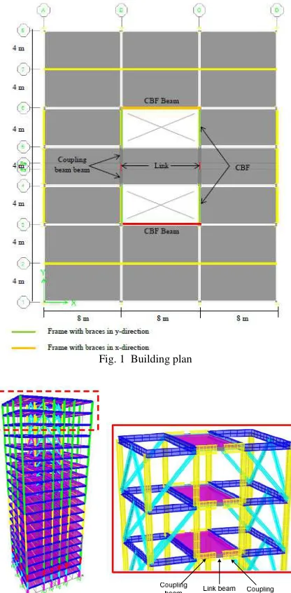
The sub-assemblage tested in this study is based on a hypothetical building with core frames consisting of two concentrically braced frames connected by a coupling beam (Figs. 1 and 2). The structure is a 20-story building located in Jakarta, Indonesia, with building plan shown in Fig. 1. In the x-direction, this building adopts concentrically braced frame system, while in the y-direction, it uses core frame system where a steel link beam is placed in the mid-span of each coupling beam so that the seismic energy is expected to be dissipated by steel link beams (Fig. 2). The link beams as mechanical damper could be designed as the only element to perform plastic deformation, while all other structural elements in the building are designed to remain elastic. This will certainly control the building damages due to a severe earthquake to be located mostly at the link beams, similar to the mechanism of the eccentrically braced frame system.
kg/m2 for roof story and 150 kg/m2 for other stories; the live load of 100 kg/m2 for roof story and 250 kg/m2 for other stories. Meanwhile, earthquake load was analyzed using response spectrum analysis. It was assumed that the soil type of this building is soft soil (SE). The analysis and design of these buildings were carried out using SAP 2000 [6] according to Indonesian Seismic and Steel Building Code SNI 1726:2012 [7] and SNI 1729:2015 [8]. There are four major steps involved in the design procedure: (1) determination of building geometry, initial element size, and load criteria, (2) design of link element as a deformation-controlled element, (3) design of other elements as force-controlled elements using capacity design concept, and (4) checking of failure mechanism through pushover analysis. More in-depth explanation related to the numerical modeling could be found in Moestopo et al. [9]
Fig. 1 Building plan
Fig. 2 Three-dimensional view of core frame system
A. Test Setup
Based on the numerical analysis described in the previous section, a half-scale sub-assemblage was fabricated
and loaded with cyclic loading test to investigate the seismic performance of the shear link and the coupling beam. The span between two columns of the sub-assemblage is 2000 mm, whilst the height of the column is modeled from mid floor to mid floor and taken as 2000 mm as well (Figs. 3 and 4). The columns use steel section WF 350x350x12x19, the coupling beams use WF 400x200x8x13, and link beam uses WF 150x75x5x7. The material for columns and coupling beams was made from Indonesian steel (BJ 37 or A36 equivalent).
As mentioned in the introduction, research of link beam connected to coupling beam using A36 steel is still limited. The only test parameter is the source of material for the link. Specimen JPN used Japanese steel (SS400) and fabricated in Japan, while Specimen INA used Indonesian steel (BJ 37) and fabricated in Indonesia. The material used for the sub-assemblage is summarized in Table 1.
Fig. 3 Plan of sub-assemblage
Fig. 4 Photo of the test setup
TABLEI
MATERIAL FOR SUB-ASSEMBLAGE
Spec Link Beam Coupling Beam Column
JPN SS400
BJ 37 BJ 37 INA BJ37
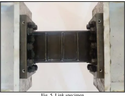
Fig. 5 Link specimen
B. Specimen Design
To ensure the replaceability of link specimen, columns and coupling beams will be designed to remain in elastic throughout the loading history and therefore, a capacity design is adopted. The following paragraphs show the capacity design check to ensure no yielding of coupling beams and columns would occur during the test.
The nominal shear strength capacity, Vn of a link beam
(WF 150x75x5x7) can be calculated using Equation (1):
(
)
0.6 F 2
n y f w
V = × × D− t ×t (1)
where Fy is the nominal yield strength of steel section, D is
the height of section, tf is the thickness of the flange, and tw
is the thickness of the web. The term (D-2tf)×tw represents
the area of the web. By substituting all the values, the nominal shear strength capacity of a link beam Vn is 97.92
kN as shown in Equation (2):
(
)
0.6 240 150 2 7 5
n
V = × MPa× − × mm × mm (2a)
97.92
n
V = kN (2b)
Using the capacity design concept, the required shear for coupling beam, Vu,cb is taken as the calculated nominal shear
strength capacity of a link amplified by two factors, i.e., Ry and over-strength factor, as shown in Equation (3):
,
u cb n y
V = ×V R ×overstrength factor (3)
where the value of Ry is taken as 1.5 which represents the
ratio of expected material yield strength to the minimum yield strength and the over-strength factor is taken as 1.5. Hence, the required shear force for coupling beams, Vu,cb is
220.32kN as shown in Equation (4):
, 97.92 1.5 1.5 220.32
u cb
V = kN× × = kN (4)
Knowing the shear force acting on coupling beam, the moment acting on coupling beam Mu,cb can be calculated
using Equation (5):
, ,
u cb u cb cb
M =V ×ℓ (5)
where
ℓ
cis the length of a coupling beam, and is taken as 900 mm. Hence, the required moment acting on coupling beam, Mu,cb is 198.29kN-m.On the other hand, the design plastic moment of a coupling beam (WF 400x200x8x13) is equal to 277.77 kN-m as calculated in Equation (6):
(
)
, 277.77
n cb x y
M Z F kN m
φ =φ × = − (6)
where Zx is plastic section modulus and taken as 128592 mm3.
Comparing the design plastic moment and required
moment at coupling beam,
φ
Mn cb, Mu cb, =1.26, it can beconcluded that the design of the coupling beam is sufficient and no yielding of coupling beam would occur when the link beam reaches its shear capacity.
Meanwhile, the acting axial and moment force on columns were obtained from sub-assemblage analysis using SAP2000. The values of axial and moment forces are then amplified using two factors, i.e., Ry and over-strength factor as shown in Equations (7) and (8):
, 119.55
u c y
P = kN R× ×overstrength factor (7a)
, 119.55 1.5 1.25 224.16
u c
P = kN× × = kN (7b)
, 179.33
u c y
M = kN m R− × ×overstrength factor (8a)
, 179.33 1.5 1.25 336.24
u c
M = kN m− × × = kN m− (8b) where the over-strength factor for the column is taken as 1.25 for this study.
The design axial force and moment of a column are calculated using Equations (9) and (10), respectively:
, 0.9
c n cP Ag Fcr
φ
= × × (9a)2
, 0.9 17390 233.82
c n cP mm MPa
φ = × × (9b)
, 3659.73
c n cP kNm
φ
= (9c)where Ag is the gross area, and Fcr is the critical inelastic
compressive stress.
0.9
bMn Zx Fy
φ
= × × (10a)3
0.9 2493182 240
bMn mm MPa
φ = × × (10b)
538.53
bMn kNm
φ = (10c)
Finally, the capacity of the column is checked using axial-moment interaction equation as shown in Equation (11):
0.03 0.62 0.65 1.0
2
u u
c c b n
P M
P M
φ +φ = + = < (11)
Equation (11) shows that column capacity is adequate to resist combined axial and moment load.
C. Instrumentation
There are two main data that were acquired through the LVDT, which configuration is shown in Fig. 6. First, is the link rotation which is acquired through the diagonal configuration of LVDT 2, 3, 4, 5, 6, 7, 8, and 9 of both faces of the link (Fig. 7). The second one is frame drift. Frame drift or column drift is calculated as the average between the left and right column drift. Left column drift is measured by using LVDT 12, 13, and 14 while right column drift is measured by using LVDT 15, 16, and 17. LVDT 1 and 18 is used to measure the horizontal displacement on actuator and loading beam.
There are also LVDTs that were used to measure potential slip. LVDTs 10 and 11 are used to measure potential slip on link-to-coupling beam connection. LVDT 21 and 22 are used to check potential slip between the reaction unit and strong floor.
used on the specimen. Four rosettes (SG 7, 8, 9, 10) were used on one side of the web. SG 11, 12, 13, and 14 were used to measure the strain of the flange of the link. One gauge was used on each column (SG 1 and 4). Two gauges were used on top, and bottom flange of coupling beam ends near column (SG 2, 3, 5, and 6). The locations of strain gauges are indicated in Figs. 6 and 7.
Fig. 6 Instrumentation plan
Fig. 7 Detail instrumentation on link beam
D. Loading Protocol
The AISC [9] loading protocol adopted in this study is the one used for cyclic tests of link-to-beam moment connections in eccentrically braced frames as tabulated in Table 2.
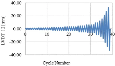
However, the source of input protocol for the horizontal actuator is from horizontal displacement. So, a transformation rule from link rotation to horizontal displacement must be derived using the geometry. The link rotation angle ( ) corresponds to the horizontal displacement at LVDT 12, ( ) can be expressed in Equations (12) to (14) and illustrated in Fig. 8.
TABLEIII LOADING PROTOCOL
No. Number of Cycles γ [radian]
1 6 0.00375
2 6 0.005
3 6 0.0075
4 6 0.01
5 4 0.015
6 4 0.02
7 2 0.03
8 1 0.04
9 1 0.05
10 1 0.07
11 1 0.09
12 1 0.02
L e
γ = θ (12)
12 12
12 1750
LVDT LVDT
H mm
θ=∆ =∆ (13)
12 12
300
1750 2000
LVDT
e mm
H mm
L mm
γ× γ×
∆ = = (14)
Fig. 8 Transformation from link rotation to displacement target
Hence, the input displacement into the actuator is set as shown in Fig. 9.
III.RESULT AND DISCUSSION
A. Material Test
Tensile tests were carried out for all material used in the experiment. Columns, coupling beams, and all link specimens from Indonesia (INA) were fabricated from BJ37 steel (Fy = 240 MPa, Fu = 370 MPa), equivalent to ASTM A36 steel. All link specimens from Japan (JPN) were fabricated from SS400 grade steel (Fy=235 MPa, Fu = 400 MPa). Tensile tests were conducted following the Indonesian standard SNI 07-0371-1998 [10] which refers to JIS Z 2201 [11]. The results of the tensile test are shown in Tables 3 to 6. The average web yield strength for specimen INA was 365.32 MPa, while that for specimen JPN was 339.63 Mpa. The average flange yield strength for columns and coupling beams were 290 MPa and 388 MPa, respectively.
TABLEIIIII
AVERAGE TENSILE TEST RESULT OF LINK BEAM
Specimen Location Fy Fue εu Fye/Fue [MPa] [MPa] [mm/mm'] [-]
INA web 365.32 498.14 0.3049 0.73
INA flange 344.46 444.75 0.2450 0.78
JPN web 339.63 452.41 0.3007 0.75
JPN flange 323.64 449.66 0.4023 0.72
TABLEIVV
AVERAGE TENSILE TEST RESULT OF COUPLING BEAM
Specimen Location Fye Fue εu Fy/Fu [MPa] [MPa] [mm/mm'] [-]
INA web 435.7 545.6 0.1392 0.80
INA flange 388.8 518.3 0.1998 0.76
TABLE V
AVERAGE TENSILE TEST RESULT OF COLUMN
Specime n
Location
Fye Fue εu
Fye/Fu
e
[MPa] [MPa] [mm/mm'] [-]
INA web 299.8 459.6 0.2214 0.66
INA flange 290.0 453.94 0.1699 0.64
B. Specimen JPN
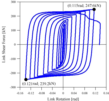
The plot of hysteretic loops between link shear vs. total link rotation is shown in Fig. 10. Specimen JPN was loaded until the link collapsed. The maximum link shear force was 247.6 kN, which occurred at total link rotation of γ = 0.121 rad. The maximum link plastic rotation was obtained: γp = 0.109 rad at last pull cycle and γp = 0.1160 rad at last push cycle or average of γp = 0.112 rad. The test was terminated after fracture occurred at the bottom left of the flange (Fig. 11).
Based on the failure mechanisms described in the previous chapters, the link element is yielded as expected, while all other elements (columns and coupling beams) remain in an
elastic stage. Strain gage measurement presented in Figs. 12 and 13 indicate the stresses occurred at columns and coupling beams respectively were still in the elastic range.
-0.16 -0.12 -0.08 -0.04 0 0.04 0.08 0.12 0.16 -300
-200 -100 0 100 200 300
Fig. 10 JPN: Link shear vs. Total link rotation
Fig. 11 Fracture at the bottom left flange and final deformation of link specimen JPN
-400 -300 -200 -100 0 100 200 300 400 -300
-200 -100 0 100 200 300
-400 -300 -200 -100 0 100 200 300 400 -300
-200 -100 0 100 200 300
Fig. 13 JPN: load vs. coupling beam stress
C. Specimen INA
The plot of shear link force against link rotation (Fig. 14) shows that the link attained its maximum shear-force of 267.2 kN at total link rotation of 0.113 rad or plastic rotation of 0.111 rad, as the test was terminated after fracture occurred at the bottom link flange (Fig. 15). Rosette strain gages measurement indicated that the first yielding of link web occurred at cycle 24, which corresponds to link rotation of 0.0028 rad.
-0.16 -0.12 -0.08 -0.04 0 0.04 0.08 0.12 0.16 -300
-200 -100 0 100 200 300
Link Rotation [rad] (0.113rad; 246.7N)
(0.113rad; 267.2kN)
Fig. 14 INA: Link shear force vs. total link rotation
Fig. 15 Fracture at the bottom left of the flange and final deformation of link specimen INA
Figs. 16 and 17 indicate that no yielding of columns and coupling beams occurred during the test.
-400 -300 -200 -100 0 100 200 300 400 -300
-200 -100 0 100 200 300
Fig. 16 INA: load vs. column stress
-400 -300 -200 -100 0 100 200 300 400
-300 -200 -100 0 100 200 300
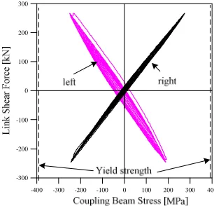
Fig. 17 INA: load vs. coupling beam stress
D. Comparisons of Seismic Performance
-0.16 -0.12 -0.08 -0.04 0 0.04 0.08 0.12 0.16 -300
-200 -100 0 100 200 300
Fig. 18 Comparison of hysteretic loops
Moreover, comparisons of secant stiffness degradation and cumulative energy dissipation of these two specimens are shown in Figs. 19 and 20, respectively. They indicate that these two specimens performed identically and showed no appreciable difference regardless of the difference in material. This verifies a good seismic performance of the link beam attached to coupling beam system.
Fig. 19 Comparison of secant stiffness degradation
Fig. 20 Comparison of energy dissipation
E. Replaceability of Link Beam
In this experimental work, the sub-assemblage (column and coupling beam) was used throughout the experimental study. After each test, the link specimen was removed, and the inspection was conducted to the column, coupling beam, and the end-plate connection between the coupling beam and the link specimen (Figs. 21 and 22).
As discussed previously, after each testing, no indication of yielding in coupling beam and column of the
sub-assemblage were observed. Thus, the sub-sub-assemblage did not experience any permanent deformation.
Fig. 21 Link to coupling beam coupling beam connection before testing
Fig. 22 Coupling beam after testing and before the next testing (top view)
Further inspection of the end-plate connection of the coupling-beam after the completion of each testing showed that the followings are consistently performed:
• There was no indication of damage on the end-plate surfaces as well as around the perimeter surface of all bolt-holes in both end-plates of coupling beam.
• There was no indication of damage in all bolts that were used in connecting end-plates of both coupling beams and link specimen.
• There was no significant slip occurred between end-plate of coupling beam and end-end-plate of link specimen.
The experimental work verified the replaceability of the link in the sub-assemblage and confirmed the use of the seismic device developed in this research project.
IV.CONCLUSION
Based on the cyclic test of two specimens made of the Japanese and Indonesian material, results and conclusions have been obtained as follows:
• A seismic resisting structural system of steel core-frames has been developed. The system consists of two concentrically braced frames connected with coupling beams and shear links. The shear link has been designed by a capacity design to yield and dissipate the energy while the coupling beam and other elements of the core frames (beam, column and bracing) remain elastic.
decreasing strength indicated in the hysteretic curve. At the same time, there was no indication of any damage (yielding, buckling) in coupling beam (web, flange, end-plate, bolts) and column. Yielding is localized only in web and flange of the link. This verified the behavior of the link and the sub-assemblage as a seismic device, as specified in the code (AISC 341-10).
• The Indonesian shear link specimen showed higher values of shear resisting force due to its slightly higher value of yield-strength as compared to the Japan link specimen. However, both specimens showed the same ductility when they reached the maximum strength with its plastic rotation beyond 0.08 rad.
• The result of cyclic loading test has confirmed that damaged link can be easily removed and replaced with the new link with the same geometry and the same bolt configuration since the remaining structure (coupling beams, columns and its connections) remain elastic and they always returned to its original position after the damaged link was removed.
ACKNOWLEDGMENT
This research is funded AUN/SEED-Net Project No. ITB CRI 1501 and 1601. The authors would like to extend their gratitude to Prof. Kazuhiko Kasai and Prof. Satoshi Yamada for their advice and discussion as well as to Nippon Steel
and Sumitomo Metal Corporation for counterpart-fund and kind support.
REFERENCES
[1] Hjelmstad, K.D. and Popov, E.P., “Cyclic Behavior and Design of Link Beams,” Journal of Structural Engineering, vol.109, pp. 2387-2403, Oct. 1983.
[2] Kasai, K. and Popov, E.P., “General behavior of WF steel shear link beams,” Journal of Structural Engineering, vol. 112, No. 2, 1986. [3] Bruneau, Michel, Ductile Design of Steel Structures,2nded.. USA:
McGraw-Hill, 2011.
[4] Ji, X., Ma, Q., Wang, Y., and Okazaki, T. “Cyclic Behavior of Steel Shear Links used in Replaceable Coupling Beam,” in Proc. Tenth US National Conference on Earthquake Engineering, 2014.
[5] Ji, X., Wang,Y., Ma,Q., and Okazaki,T. “Cyclic Behavior of Very Short Steel Shear Links,” Journal of Structural Engineering, 10.1061/(ASCE)ST.1943-541X, 04015114, 2016.
[6] Structural Analysis Program 2000, CSI, 2000.
[7] Seismic Provision for Structural Building and Non-Building (In Indonesian), Indonesian Standard - SNI 1726, 2012.
[8] Specification for Structural Steel Buildings (In Indonesian), SNI 1729, 2015.
[9] Moestopo, M., Kusumastuti, D., Lim, E., Akbar, U. K., Ramadhita, M. S., Tenderan, R., “Application of Seismic Devices for Core Frames of High-Rise Buildings,” Institut Teknologi Bandung, Bandung, Collaborative Research Program with Industry (AUN/SEED-Net), Final Report, 2017.
[10] Seismic Provisions for Structural Steel Buildings. ANSI/AISC 341-10, 2010.
[11] Tensile Test for Metallic Materials (In Indonesian), SNI 07-0371, 1998.