٭
Corresponding Author, Email: [email protected]
Optimum Design of Brush- Less DC Motor with
Minimum Torque Pulsation Using FEM& PSO
M. Pourjafari
1, E. Fallah Choolabi
2*, M. Jafarboland
31- M.Sc. Student, Department of Engineering, University of Guilan, Rasht, Iran 2- Assistant Professor, Department of Engineering, University of Guilan, Rasht, Iran
3- Associated Professor, Department of Electrical Engineering, Malek Ashtar University of Technology, Shahin shahr, Iran
A
BSTRACTDespite many advantages of Brush-Less DC motor, torque pulsation is one of the most important
disadvantages of it. At first, an optimum primary design of BLDC motor is done using PSO algorithm. Then,
other parameters for reducing the torque pulsation are considered by the finite element method. It is shown
that the fractional slot structure has many advantages than the conventional one. Both cogging and ripple
torque have been reduced for the fractional structure. In the next steps, other important torque pulsation
parameters, such as magnet embrace, offset and skew are considered. Proper embrace, skew and offset are
achieved for reducing the torque pulsation by the nonlinear finite-element analysis.
K
EYWORDS1-INTRODUCTION
Nowadays, due to offering several advantages compared to the other motors, permanent magnet Brush-Less DC motor (BLDC) is widely used in different applications such as robots, air conditioners, submarines and etc. Such advantages include having higher efficiency and shrinking the maintenance costs and noise due to eliminating brushes. Furthermore, since it is fed with DC current, it can be employed in situations where no AC power supply exists. Though the performance of BLDC is satisfactory, few features of this motor still need improving. Vibration and noise are two major deficiencies of BLDC that must be addressed. Vibration and noise are the side effects of torque pulsation. Torque pulsation is, in turn, the resultant of two different types of torque, i.e., ripple torque and cogging torque. Ripple torque is produced by the interaction of stator winding and magnet linking flux [1]. Cogging torque shows the relation between the rotor magnets acting on the stator teeth or poles independent of any current [2]. In fact, cogging torque is created due to the different reluctances observed by the rotor magnet while it is rotating. The reason for this difference is the slot opening that causes difference in the air gaps, observed by magnet rotor. In other words, ripple torque is created by the mutual torque while cogging torque is created by reluctance torque [1]. Cogging torque plays an important role in generating an undesirable noise and vibration in BLDC. So, it should be reduced or even removed.
There are some different techniques for minimizing the torque pulsation. Some of them tried to modify the excitation current [3-9], while some others have focused on optimizing the motor design to achieve smoother torque [10-13]. The relationship between the number of magnet poles and the number of stator slots can influence cogging torque, because as each magnet passes by stator slots, it produces cogging torque [2]. Cogging torque frequency is the Lowest Common Multiple (LCM) of all slots and poles. By increasing the frequency, the amplitude of cogging torque decreases. Increasing the number of phases has a significant importance in reducing the torque pulsation. Increasing the phases increases the torque pulsation frequency and decreases its amplitude. The role of the number of phases on torque pulsation has been considered in [1]. One of the fundamental methods to reduce the cogging torque is skewing. Cogging torque is maximum without skewing and can be eliminated with one slot pitch skew. Skew can apear on magnets or slots [1,2]. Changing the magnetizing direction of the magnet can affect the cogging torque. Skewing, changing magnetization, considering the role of stator winding distribution and the number of stator slots have been considered in [14]. In [15], the effect of pole shape on cogging torque is studied and an optimal pole shape to reduce cogging torque is achieved. In [16], the core shape is optimized to reduce the cogging torque, and in [17], the magnet shape is optimized according to the magnetization direction for maximizing the back-EMF and minimizing the cogging torque and THD.
In this paper, an efficient procedure for designing and
optimizing BLDC motor for reducing the torque pulsation is presented. The goal of this paper is to design a 3-phase, 4-pole, 800 watt output power, 7000 RPM and 24 volt BLDC motor with a minimum torque pulsation. After the primary designing, some different techniques are considered to minimize the torque pulsation.
In section two, motor equations are given. In section three, an optimized preliminary design for BLDC was done, thanks to PSO (the Particle Swarm Optimization) algorithm. In the next steps, the influences of other parameters on torque pulsation, especially magnet offset, embrace and skew has been considered to achieve the least torque pulsation, thanks to the finite element method using Maxwell software.
2-BRUSHLESSDCMOTOREQUATIONS
The relationship between air gap flux density (Bg) and magnet flux density (Br) is [2, 13]:
1 K Brl Bg
g R Kr
Lm
(1)
The tooth body width is [2,13]:
2 Bg Rro tb
N K Bs st t
(2)
The stator yoke width is [2, 13]:
Bg Rro sy
N Km st syB
(3)
And the rotor yoke width is [2,13]:
Bg Rro ry
N K Bm st ry
(4)
where
tb ,
sy and
rygiven in Eq.s (2)-(4) are shown in Fig. 1. In the ideal conditions and with Nspp, which is equal to 1, the torque produced by each phase can be expressed as [2,13,18]:2 EI
T N NB L Rm g st roI m
FIGURE 1: BLDC MOTOR CROSS-SECTIONAL AREA [2]
where Nspp is thenumber of slot per pole per phase. There are two coil sides per slot while each of them contains N turns. Hence, the resistance per slot becomes [2,13,18]:
2 4 Lst N R
slot
K As s
(6)
Based on the aforementioned equations and Fig. 1, the slot area can be expressed as [2,13,18]:
2 2
[( ) ( ) ] (
As Rso sy Rro g dsht tb Rso sy Ns
) Rro g dsht
(7)
dsht is the sum of Hs0 and Hs1 that are shown in Fig. 2. Eq.s (1)-(7) are needed for designing a BLDC motor.
FIGURE 2: STATOR SLOT FIGURE
3-DESIGN AND OPTIMIZATION OF THE STRUCTURE OF MOTOR FOR REDUCING TORQUE PULSATION
A. A Fundamental Design of Motor Using the PSO Algorithm [19, 20]
There are some free parameters in the above equations that should be selected properly in order to reach an optimal design and hence, reduce the torque pulsation. Free parameters are selected as follows:
Rr, g, Lm, Hs0, Hs1 andHs2. The three last parameters are shown in Fig. 2. These parameters determine stator slot construction, stator and rotor yoke thickness and rotor configuration. The Particle Swarm Optimization (PSO) algorithm is used to achieve the optimum values for the free parameters.
Eq.s (1)- (7) are used for the purpose of the optimization using PSO. There are many parameters in these equations. Some of them are free parameters that mentioned before and should be optimized. But other parameters should be initialized before the optimization, such as stator exterior radius, stator and rotor yoke flux density and etc. These parameters are given in Table 1. Stator exterior radius is usually to be selected experimentally. Stator yoke flux density, rotor yoke flux density and tooth flux density are selected below saturation level of the ferromagnetic material. Br and
Rare the magnet specifications. Selecting magnet sets these parameters. Now, motor design begins. The goal of this paper is to design a 3-phase, 4-pole, 800 watt output power, 7000 rpm and 24 volt BLDC motor. First of all, the design begins with the traditional structure for three phases i.e. 12-slot, 4-pole (coil span equal to 3 slots or full pitch). To achieve the maximum slot fill factor and increase efficiency, the double layer winding is selected. In this paper, PSO algorithm is used for optimizing the free parameters. However, at first, a proper objective function must be defined. The problem is that there is no analytical relationship for expressing the torque pulsation, so another objective function should be found. There are three constants in BLDC motor; the torque constant, the back EMF constant and the motor constant. The torque constant and the back EMF constant are dependent on N, but until the slot area remains unchanged, the product NI is constant [2]. Therefore they are not good indicators of the motor performance. The torque constant is defined below [2, 13]:
T Kt
I
(8)
The back EMF constant is defined as follows [2, 13]
Eb Ke
m
(9)
The motor constant is defined follows [2, 13]:
2 T Km
I R
(10)
The motor constant, defined in (10), is a better performance indicator [2].
one can write the motor constant for one phase of this ideal motor [2, 13]:
/ 2
T
Km B R K L Ns st m sA g ro
I RslotNm
(11)
The motor constant is not dependent on either current or the number of turns N. So, it won't change as long as the slot fill factor is fixed. Therefore, the motor constant can be considered to be a good indication of the motor performance. A bigger motor constant leads to a better performance. Thus, the motor constant is selected as the objective function. Using Eq.s (1)-(7), initialized parameters and the motor constant, PSO algorithm can be used for optimizing the free parameters. After determining free parameters, all motor dimensions are achievable. The torque equation in all rotating machines can be expressed [2, 13]:
2
TKD Lst (12)
It is known that the torque is proportional to the motor length. One can increase the motor length to increase torque and reduce speed while the power is kept constant. To achieve the desired speed, motor length is to be altered in the constant power. At first, motor length is considered 60 mm. After the finite element simulation, if the motor speed differed from 7000 RPM, the motor length should be changed to adjust the speed. The stator exterior radius is set to be 38 mm, based on the experiment. The magnet is NdFeBr of type 35 EH with Br equal to 1.21T and a relative permeability of 1.099. The values of different constants and parameters, which are used for the simulation, are shown in Table 1.
As it is clear in Fig. 1, the sum of the free parameters and the stator yoke should be equal to the stator exterior radius.
0 1 2
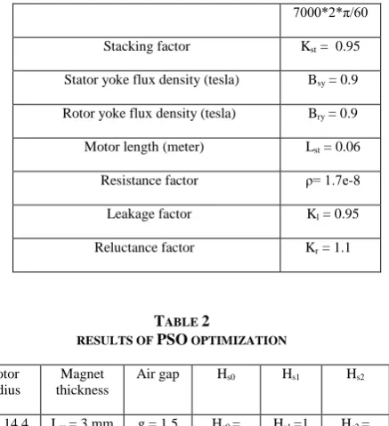
RrLm g Hs Hs Hs syRso (13) Furthermore, all of the free parameters have the proper upper bound and lower band to change in the correct span. These two constraints should be considered in PSO programming. The optimized values of the free parameters, after PSO optimization, are shown in Table 2.
TABLE 1
VALUES OF CONSTANTS AND PARAMETERS FOR BLDCMOTOR DESIGN
Ns = 12
Number of slots
Nm = 4 Number of poles
Bt = 1.2 Tooth flux density (tesla)
Rso = 0.038 Exterior stator radius (meter)
Br = 1.21 Magnet flux density (tesla)
μr= 1.099 Magnet permeability
Ks = 0.65 Slot fill factor
ωm = Nominal rotor speed (rad/sec)
7000*2*π/60
Kst = 0.95 Stacking factor
Bsy = 0.9 Stator yoke flux density (tesla)
Bry = 0.9 Rotor yoke flux density (tesla)
Lst = 0.06 Motor length (meter)
ρ= 1.7e-8 Resistance factor
Kl = 0.95 Leakage factor
Kr = 1.1 Reluctance factor
TABLE 2
RESULTS OF PSO OPTIMIZATION
Hs2 Hs1
Hs0 Air gap Magnet
thickness Rotor
radius
Hs2 = 6.1 mm Hs1 =1
mm Hs0 =
0.5 mm g = 1.5
mm Lm = 3 mm Rr = 14.4
mm
The rotor exterior radius (Rro) is the sum of the rotor radius and the magnet thickness. Using Table 2 parameters and Eq.s (1)- (7), other motor dimensions which should be used in Maxwell software for the finite element analysis, are achievable. These parameters are shown in table 3. Hs0, Hs1, Hs2, Bs0, Bs1 and Bs2 are shown in Fig. 2. Bs0 is set experimentally to 1.5 mm. The number of conductors per slot and the number of strands for each conductor are set by the Maxwell software automatically. Using Table 1, Table 2 and Table 3 data, the finite element simulation is possible. Motor embrace assumed to be 1 and its skew and offset assumed to be zero for this simulation. Next, these parameters will be studied. The designed motor cross-sectional area and winding layout (coil span equal to 3 slots) are shown in Fig. 3.
TABLE 3
LAST DIMENSIONS FOR BLDCMOTOR DESIGN
Slot area 0.39875 cm2
Tooth Thickness ωtb = 5.7 mm
Stator yoke thickness ωsy = 11.5 mm
Rotor yokes thickness ωry = 11.5 mm
Slot parameter Bs1 = 5 mm
Slot parameter Bs2 = 8.1 mm
Number of conductors per slot 14
Number of strands for each conductor 4
Parallel branches 4
Slot parameter Bs0 = 1.5 mm
(a) (b)
FIGURE 3: (a).DESIGNED MOTOR CROSS-SECTIONAL AREA.(b). WINDING LAYOUT
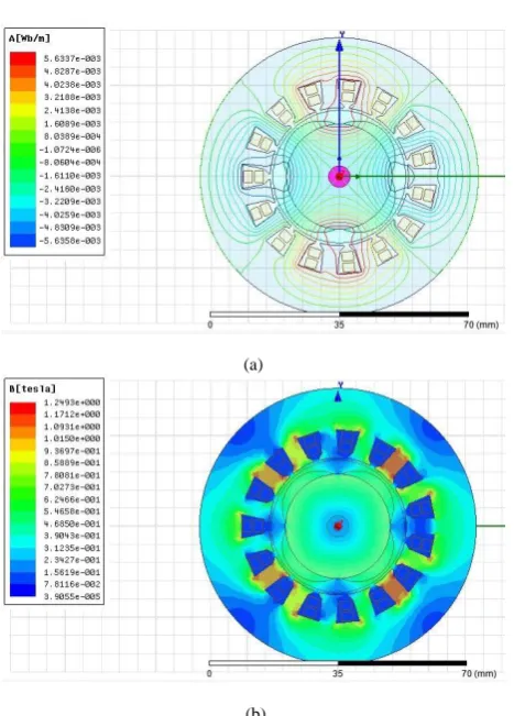
Motor triangulation in Maxwell software is shown in Fig. 4, and the flux lines and the flux density are shown in Fig. 5.
FIGURE 4: MOTOR TRIANGULATION FOR FINITE ELEMENT ANALYSIS
(a)
(b)
FIGURE 5: (a).FLUX LINES.(b).FLUX DENSITY IN MOTOR CROSS-SECTIONAL AREA
After the finite element simulation, the motor speed differed from 7000 RPM. So, the motor length is changed from 60 mm to 64.1 mm to adjust the speed to 7000 RPM. The torque waveform for the designed motor is shown in Fig. 6
The torque pulsation for designed motor is:
1.6197 1.3798 max
17.39% 1.3798
T Taverage
Tpulsation
Taverage
(14)
B. Fractional Slot Motor
The simulated motor in the last section had 12-slot, 4-pole with 3 slots coil span (full pitch). Now the fractional slot motor is considered. As mentioned before, the cogging torque frequency is the Lowest Common Multiple (LCM) of the number of slots and number of poles. Greater cogging torque frequency reduces its amplitude. In fractional slot motor, LCM is bigger. Furthermore, as stated in [2] and [13], the back emf waveform in the fractional slot is more sinusoidal than that of the conventional structures. Sinusoidal back emf reduces torque pulsation. So, designing motor using fractional slot structure has many advantages. Among the possible configurations, combination of pole and slot with maximum LCM is selected. There are two possible combinations. 9-slot, 4-pole with LCM equal to 36 and 15-slot, 4-pole with LCM equal to 60. More than 15 slots is not feasible, because the slot area will be very small for this specific motor. Therefor, a 15-slot, 4-pole combination is selected (with coil span equal to 3 slots). Coil span is 144 electrical degrees for this structure. Changing the number of slots from 12 to 15 will change Bs1, Bs2, tb and the slot area. The results of this modification are expressed in Table 4. Parallel branches in fractional slot structure could not be more than 1. Number of conductors and number of strands are properly set due to Maxwell software automatically.
TABLE 4
MOTOR DIMENSIONS WITH 15-SLOT,4-POLE AND COIL SPAN =3
Rr 14.4 mm
Lm 3 mm
g 1.5 mm
Hs0 0.5 mm
Hs1 1 mm
Hs2 6.1 mm
As 0.319 cm2
ωtb 4.6 mm
ωsy 11.5 mm
ωry 11.5 mm
Bs0 1.5 mm
Bs1 4 mm
Bs2 6.5 mm
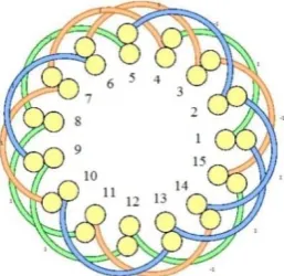
Motor winding layout is shown in Fig. 7. The torque waveform for this structure i.e. 15-slot, 4-pole, zero offset, and unity embrace and with skewing, is shown in Fig. 8. The torque pulsation for this figure is 8.45%. As it is clear, the torque pulsation is reduced for the fractional slot structure. Now, cogging torque is compared for these two structures. Cogging torque diagram is also achievable with Maxwell software. The cogging torque for the first design is shown in Fig. 9, (12-slot 4-pole) and the cogging torque for the second design is shown in Fig. 10. (15-slot 4-pole)
FIGURE 7: WINDING LAYOUT FOR 15-SLOT,4-POLE, SKEW =0, EMBRACE=0.85 WITH COIL SPAN =3(FRACTIONAL SLOT PITCH)
FIGURE 8: TORQUE WAVEFORM FOR 15-SLOT,4-POLE WITH SKEW =0 AND EMBRACE =1
FIGURE 10: COGGING TORQUE WAVEFORM FOR 15-SLOT, 4-POLE WITH SKEW=0 AND EMBRACE=0.1
Obviously, cogging torque frequency is increased and its amplitude is decreased for 15-slot, 4-pole structure. As expected, in the first figure, the amplitude is 0.1893 N.m. while in the second figure, the amplitude is 26.6e-3 Nm. As a result, using the fractional slot combination, the torque pulsation is reduced from 17.39% to 8.45% and the cogging torque is reduced from 0.1893 Nm to 26.6e-3 Nm. Hereinafter, other parameters (offset, skew, …) will be considered through the fractional slot combination.
C. Skew Role
Cogging torque equation can be expressed as follows [1,2]: 1 2 2 dR Tcog d
(15)
As mentioned before, eliminating the cogging torque is so important for reducing noise and vibration as well. One of the fundamental methods for reducing cogging torque is skewing. Cogging torque is maximum without skewing, however it can be eliminated with one slot pitch skew or skew equals to 1 in stator or magnet length [1,2]. Based on (15), reducing
dR/d
will reduce the cogging torque. Using skewing, the netdR/d
decreases. Since different parts of magnet have different reluctance variations relative to each other, their variations are not in the same phase, hence the net variation is reduced. However, increase of skew from zero to one can increase the torque pulsation. Similarly, the mechanical construction would become more complicated with skewing [2]. So, finding the minimum skew, which can eliminate the cogging torque, is desirable. As demonstrated in [2], the minimum skew for eliminating cogging torque can be obtained:( , ) Ns skew
LCM Ns Nm
(16)
In 12-slot, 4-pole, αskew can be given as:
12 12 1 12 (12, 4) skew LCM
αskew equals to 1 means one slot pitch skew in motor length for each stator slot. αskew for 15-slot, 4-pole is:
15 15 0.25 60 (15, 4) skew LCM
Likewise, αskew is equal to 0.5 and one slot pitch can eliminate cogging torque for this case. Now, the role of skew on cogging torque will be considered, this is done through the finite element method using Maxwell software. The results of the finite element analysis for 15-slot, 4-pole motor with coil span equals to 3, offset equals to zero and embrace equals to 1 with different skews are expressed in Table 5.
In skew equals to 0.5 and 1, cogging torque is almost zero. In skew equals to 0.25, cogging torque is less than its around skews, as expected. As mentioned before, the minimum skew with the lowest cogging torque is needed, so skew equals to 0.5 is selected for the subsequent optimizations.
TABLE 5
DIFFERENT SKEWS FOR 15-SLOT,4-POLE MOTOR WITH COIL SPAN=3 AND EMBRACE=1 AND OFFSET=0
M o to r sp ee d (RP M ) M o to r len g th (m m ) Co g g in g t o rq u e (Nm ) To rq u e p u lsa ti o n ( % ) Av era g e to rq u e (N.m ) M ax imu m to rq u e (N.m ) sk ew 7000.3 5 46.1 7 26.6 e-3 8.45 1.3158 1.427 0 7002.3 46.1 7 19 e-3 8.45 1.3147 1.4258 0.1 6999.4 46.2 3 6.1 e-3 8.47 1.3125 1.4237 0.2 6999.9 46.2 5 5.7 e-4 8.47 1.311 1.4221 0.2 5 6999.4 5 46.2 8 4.1 e-3 8.48 1.3093 1.4204 0.3 7001.7 46.3 5 4.7 e-3 8.5 1.3036 1.4144 0.4 7000.8 46.4 7 2.51 e-12 8.54 1.2964 1.4071 0.5 7002.5 47.4 4.13 e-13 8.82 1.2347 1.3436 1
D. Embrace Role
Embrace is the magnet arc. According to Fig. 11, embrace is defined as follows:
Embrace
FIGURE 11: EMBRACE SHOW
is the pole pitch. Changing the embrace changes the air gap flux density. Air gap flux density has a direct impact on the stator induction back emf. An efficient back emf results in a lower torque pulsation. So, embrace has an important role on the torque pulsation. In this section, embrace role will be considered via the finite element method using Maxwell software. For considering its role, the finite element analysis will be done for different embraces and the embrace, which has the least torque pulsation will be selected. To achieve a high efficiency, the embrace ranges from 0.7 to 1 [2]. To prevent excessive drop in the motor length, the upper limit of the embrace is reduced to 0.9. The results of the finite element analysis for a 15-slot, 4-pole BLDC motor with skew equals to 0.5 and offset equals to zero with different embraces are given in Table 6.One can infer from the above table that as the value of embrace increases from 0.7 to 0.77, the torque pulsation percentage goes up. However, any further increase in the embrace value results in a declining trend for the torque pulsation percentage. An embrace value equals to 0.9 results in the least torque pulsation equals to 9.69%. So, the embrace is set to 0.9 for the next optimization.
TABLE 6
DIFFERENT EMBRACES FOR 15-SLOT,4-POLE WITH SKEW =0.5 AND OFFSET=0
Motor length (mm) Speed (RPM) Torqu e pulsati on (%) Average torque (N.m) Maximum torque (N.m) embrace 54.72 6999 10.55 1.0901 1.205 0.70 54.3 7002 10.59 1.0912 1.2067 0.71 53.9 7002 10.61 1.0944 1.2105 0.72 53.55 6997.7 10.64 1.0997 1.2168 0.73 53.15 7003.9 10.7 1.0992 1.2168 0.74 52.8 7002.9 10.74 1.101 1.2193 0.75 52.5 6999.2 10.75 1.1052 1.224 0.76 52.18 6999.8 10.78 1.1078 1.2272 0.77 51.85 7003.1 10.78 1.1104 1.2301 0.78 51.55 7001.4 10.73 1.1165 1.2363 0.79 51.25 7003.4 10.74 1.1171 1.237 0.80 51 7001.8 10.69 1.1202 1.24 0.81 50.75 6999 10.59 1.1254 1.2446 0.82 50.49 6998.3 10.5 1.1305 1.2491 0.83 50.25 6998 10.4 1.1348 1.2529 0.84 50 7000 10.3 1.1388 1.2561 0.85 49.75 7001.8 10.18 1.1433 1.2597 0.86 49.54 6998.3 10.07 1.15 1.2657 0.87 49.3 7000 9.93 1.1574 1.2723 0.88 49.1 6997.2 9.81 1.1643 1.2785 0.89 48.85 7001.3 9.69 1.1712 1.2846 0.9
E. Offset Role
Now the last important parameter is considered. Magnet offset is shown in Fig. 12. Offset changes the magnet shape. Magnet shape affects air gap flux density. As mentioned in the previous section, air gap flux density affects the torque pulsation. So, like embrace, different offsets result in different torque pulsations. The finite element mothod and Maxwell software have been used for considering the offset role. Like embrace, different offsets are being tried and the offset with the least torque pulsation will be selected. The result of this analysis for different offsets for the last designed motor with embrace equals to 0.9, 15-slot, 4-pole, skew equals to 0.5 and the motor length equals to 48.85 mm are shown in Table 7.
The maximum possible value for offset with this rotor structure is 7.3. The last three offsets have the least torque pulsation.
TABLE 7
DIFFERENT OFFSETS FOR EMBRACE=0.9,15-SLOT,4-POLE, SKEW =0.5 WITH COIL SPAN =3
FIGURE 12: OFFSET SHOW
E. Winding Factor Role
Another component which can affect the torque pulsation is the winding factor. A bigger winding factor results in more efficiency and less torque pulsation. In the previous simulations for the 15 slot motor, coil span was 3 slots. Winding factor for this structure is 0.909854. By changing coil span from 3 to 4 slots, winding factor becomes 0.951436. So, it is expected to reduce the torque pulsation. In this case, coil span is 192 electrical degrees. Winding layout is shown in Fig. 13. For the last three offsets, changing coil span from three to four has been considered and the results are given in Table 8.
The least torque pulsation is achieved with offset equals to 7.3mm. The torque pulsation reduces to 8.45% which is suitable for this motor. The flux lines and the flux density for the motor with the least torque pulsation are shown in Fig. 14.
The torque waveform for 15-slot, 4-pole, embrace equals to 0.9, skew equals to 0.5 and offset equals to 7.3 with coil span equals to 4 slots are shown in Fig. 15, and the motor cross-sectional area for this structure is shown in Fig. 16.
Motor rated current for this structure is 37.6 A. The flux density in different parts of the motor is shown in Table 9.
TABLE 8
DIFFERENT OFFSETS FOR EMBRACE=0.9,15-SLOT,4-POLE, SKEW =0.5 WITH COIL SPAN =4
Offset (mm)
Maximu m torque
(N.m)
Average torque (N.m)
Torque pulsation
(%)
Speed (RPM)
Motor length (mm)
6 1.6414 1.5091 8.76 7003.6 46.3
7 1.6982 1.5646 8.54 6998 46.6
7.3 1.7106 1.5773 8.45 6998.9 46.6
FIGURE 13: WINDING LAYOUT FOR COIL SPAN =4
(a)
(b)
FIGURE 15: TORQUE WAVEFORM FOR 15-SLOT,4-POLE, EMBRACE=0.9, OFFSET =7.3 WITH COIL SPAN =4
TABLE 9
FLUX DENSITY IN DIFFERENT PARTS OF MOTOR
Stator-Teeth flux
density (tesla)
Stator-Yoke flux
density (tesla)
Rotor-Yoke flux
density (tesla)
Air-Gap flux density
(tesla)
Magnet flux density
(tesla) 1.67393 0.716784 0.716784 0.861199 0.696755
Designed motor efficiency becomes 78.144% and its
weight is1.5334 kg. Motor final parameters are given
in Table 10.
FIGURE 16: MOTOR CROSS-SECTIONAL AREA FOR 15-SLOT, 4-POLE, EMBRACE=0.9, OFFSET =7.3, SKEW =0.5 WITH COIL SPAN
=4
TABLE 10
FINAL PARAMETERS OF DESIGNED MOTOR
Parameter Value
Rr 14.4 mm
Lm 3 mm
g 1.5 mm
Hs0 0.5 mm
Hs1 1 mm
Hs2 6.1 mm
As 0.319 cm2
ωtb 4.6 mm
ωsy 11.5 mm
ωry 11.5 mm
Bs0 1.5 mm
Bs1 4 mm
Bs2 6.5 mm
Number of phases 3
Ns 15
Nm 4
Coil span (slot pitch) 4
Skew (slot pitch) 0.5
Magnet embrace 0.9
Magnet offset 7.3 mm
Motor length 46.6 mm
Motor efficiency 78.144%
Motor weight 1.5334
4-CONCLUSION
element method. Proper embrace and offset that cause the least torque pulsation were obtained. At last, winding factor role was considered. By increasing the coil span from three to four slots for 15-slot, 4-pole, winding factor increases and torque pulsation decreases, as expected.
5-APPENDIX
TABLE 11
PARAMETERS AND VARIABLES DEFINITION
Stator exterior radius Rso
Number of slots Ns
Rotor radius Rr
number of magnet poles Nm
Rotor exterior radius (Rr + Lm) Rro
Air gap flux density Bg
Resistance of one phase R
Magnet flux density Br
Resistance of one slot Rslot
Tooth thickness ωtb
Resistivity ρ
Stator yoke thickness ωsy
Axial stack length of motor Lst
Rotor yoke thickness ωry
Winding current I
Reluctance factor Kr
magnet permeability μr
Leakage factor Kl
Motor diameter D
Magnet thickness Lm
Air gap thickness g
Tooth flux density Bt
Rotor nominal speed ωm
Slot fill factor ks
Stacking factor Kst
Number of turns per coil N
Motor torque T
Slot area As
6-REFRENCES
[1] Parsa, L., Toliyat, H.A., Goodarzi, A., “Five-Phase Interior Permanent-Magnet Motors With Low Torque Pulsation”, IEEE Transactions on industry applications, vol. 43, no. 1, pp. 40- 46, Jan/Feb, 2007.
[2] Hanselman, D.C., “Brushless Permanent Magnet Motor Design Hardcover”, 2nd edition, 2003.
[3] Favre, E., Cardoletti, L., Jufer, M., “Permanent magnet synchronous motors: A comprehensive approach to cogging torque suppression”, IEEE Transactions on Industry Applications, vol. 29, no. 6, pp. 1141- 1149, Nov, 1993.
[4] Murthy, S., Derouane, B., Liu, B., Sebastian, T., “Minimization of torque pulsations in a trapezoidal back-EMF permanent magnet
brushless DC motor”, IEEE Record of Industry Applications Conference, vol. 2, pp. 1237- 1242, 1999.
[5] Lee, G.H., Kim, S.I., Hong, J.P., Bahn, J.H., “Torque Ripple Reduction of Interior Permanent Magnet Synchronous Motor Using Harmonic Injected Current”, IEEE Transactions on Magnetics, vol. 44, no. 6, pp. 1582- 1585, June, 2008.
[6] Feipeng, Xu., Tiecai, L., Pinghua, T., “A low cost drive strategy for BLDC motor with low torque ripples”, 3rd IEEE Conference on Industrial Electronics and Applications, pp. 2499- 2502, June, 2008.
[7] Ozturk, S. B., Toliyat, H.A., “Direct Torque and Indirect Flux Control of Brushless DC Motor”, IEEE/ASME Transactions on Mechatronics, vol. 16, no. 2, pp. 351- 360, April, 2011.
[8] Gulez, K., Adam, A.A., Pastaci, H., “A Novel Direct Torque Control Algorithm for IPMSM With Minimum Harmonics and Torque Ripples”, IEEE/ASME Transactions on Mechatronics, vol. 12, no. 2, pp. 223- 227, April, 2007.
[9] Kashani, E.B., Niasar, A.H., “Implementation of a novel brushless DC motor drive based on one-cycle control strategy”, 5th Power Electronics Drive Systems and Technologies Conference, pp. 55- 60, Feb, 2014.
[10] Brage Filho, E.R., Lima, A.M.N., “Reducing cogging torque in Interior permanent magnet machines without skewing”, IEEE Transaction on Magnetics, vol. 34, no. 5, pp. 3652- 3655, Sept, 1998.
[11] Zhu, Z.Q., Howe, D., “Influence of design parameters on cogging torque in permanent magnet machines”, IEEETransaction on Energy Conversion, vol. 15, no. 4, pp. 407- 412, Dec, 2000.
[12] Bianchi, N., Bolognani, S., “Design techniques for reducing the cogging torque in surface-mounted PM motors”, IEEE Record of Industry Applications Conference, vol. 1, pp. 179- 185, 2000.
[13] Hendershot, J.R., Miller, T.J.E., “Design of
Brushless Permanent Magnet Motors
(Monographs in Electrical and Electronic Engineering)”, Publisher: Oxford University Press, 1995.
[14] Parsa, L. Hao, L., “Interior Permanent Magnet Motors With Reduced Torque Pulsation”, IEEE Transactions on Industrial Electronics, vol. 55, no. 2, pp. 602 - 609, Feb, 2008.
33, no.2, pp. 1908- 1911, March, 1997.
[16] Han, K. J., Cho, H. S., Cho, D. H., Cho, H. R., Lee, H. S., Jung, H. K., “Core Shape Optimization for Cogging Torque Reduction of BLDC Motor”, International Electric Machines and Drives Conference, pp. 416- 418, May, 1999.
[17] Kim, H. S., You, Y. M., Kwon, B. I., “Rotor Shape Optimization of Interior Permanent
Magnet BLDC Motor According to
Magnetization Direction”, IEEE Transactions on Magnetics, vol. 49, no. 5, pp. 2193- 2196, May, 2013.
[18] Kolahdooz, A., Shakeri, M., Jabbari, A., Gol, sh., “Design, Simulation and Fabrication of a BLDC Motor Speed Control”, Majlesi J. of Electrical Eng., vol. 2, no. 2, pp. 39- 48, 2008.
[19] Kennedy, J., Eberhart, R. C., “Particle Swarm Optimization”, IEEE Conference on Neural Networks, vol. 4, 1995.