Active Power Control in Grid Connected
Photovoltaic System
Ashwani Kumar Anand Prakash Gautam
UG Student UG Student
Department of Electronics & Electrical Engineering Department of Electronics & Electrical Engineering
HMRITM HMRITM
Rahul Ranjan Tarun Kumar
UG Student UG Student
Department of Electronics & Electrical Engineering Department of Electronics & Electrical Engineering
HMRITM HMRITM
AnuradhaTomar Assistance Professor
Department of Electronics & Electrical Engineering HMRITM
Abstract
This paper proposes a design of grid connected photo-voltaic (PV) system through implementation of active power control & MPPT control using MATLAB/Simulink. In the present scenario of world energy sector renewable sources are growing their importance day by day. The overall system model consists of a PV array, MPPT controller, Inverter and a distribution system to deliver usable power to the end grid. However, the output of solar arrays varies due to change of solar irradiation and weather conditions. Therefore, the maximum power point tracking algorithm is implemented in DC/DC converter to enable PV arrays to operate at maximum power point. The Perturb & Observe (P&O) algorithm is employed to control the boost converter. Then the central inverter is controlled by using the PI controller for active power control, which is necessary to ensure that all maximum power is transferred to the grid. Active power control is cost effective & it improves the efficiency of the system. After the complete designing of the grid connected photovoltaic system, we analysed the performance results of the PV system in MATLAB. Keywords: active power control, grid connected photovoltaic system, maximum power point tracking (MPPT), PI control, voltage source inverter
________________________________________________________________________________________________________
I. INTRODUCTION
In India, there is big challenge of supplying energy continuously, due to which there is many power crisis in our country. India is facing an acute scarcity which is hampering its industrial and economic growth therefore it is essential for us to use renewable sources of energy [17]. Thermal power is used mostly in order to generate energy and fulfil the energy requirement. Day by day, the demand of the energy is increasing and we are looking for various alternatives in order to fulfil the requirements [8-9]. Due to global concern on climate change and sustainable electrical power supply, renewable energy is increasingly becoming popular in the developed countries [18]. In [19] discussed, various kind on renewable energy sources which can be utilized to produce energy like wind, tidal, hydro, geothermal, solar etc. and they can play a key role in overcoming worldwide energy crisis.
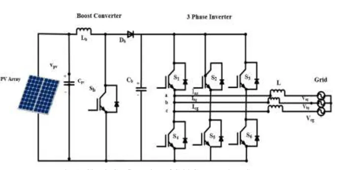
Fig. 1: Circuit Configuration of Grid Connected PV System
Fig 1 shows the circuit configuration of three phase grid connected photovoltaic system. The model of system is composed of PV array, DC-DC boost converter, DC link, DC-AC inverter & grid. The inverter transfers the active power to the grid. Also, the active power command is calculated from the PV array maximum power in order to ensure maximum power delivered to the grid.The parameters of the above discussed circuit are as:L= 1e-6 H; Lb= 0.287 H ;Cpv= 1000e-6 F ; Cb= 100e-3 F.
Now here are the parameters of the PV array module: Module Type= Sunpower SPR-305 WHT; No. of cells per module= 96; No. of series connected modules per string= 10; No. of parallel strings= 20; Voc= 64.2 V; Isc= 5.96 A; Vmp= 54.7 V; Imp= 5.58 A. The irradiance on the solar panel is 1000 W/m2, assumed to be fixed. The reference voltage is 415 V & the reference power is 2.5kW. Now, let’s discuss the next step towards the designing of the system i.e. MPPT control, whose function is to maximize the output efficiency of a solar panel or solar array.
III. CONTROL ARCHITECTURE
Mppt Control
MPPT charge controller use smart technologies, such as microcontrollers, to compute the highest possible power output at any given time. In this scenario the voltage will be monitored and regulated without power loss. Therefore in the same conditions as above, where the input voltage is higher than the output voltage, the MPPT charge controller will lower the voltage and simultaneously increase the current to the batteries. This results in higher power transfer efficiencies, which means less solar power is lost during the storage process [1].The peak power point tracking techniques vary in many aspects, such as: simplicity, convergence speed, digital or analog implementation, sensors required, cost, range of effectiveness, etc. [2] There are many MPPT algorithms that can be implemented in the MPPT control such as Perturb & observe , incremental conductance, constant voltage method, fuzzy logic control, neutral network etc. But, we are implementing P&O algorithm in the MPPT control because it can be implemented simply and the MPPT controllers available in the market are mostly programmed with this algorithm.
Fig. 2: Flow Chart of P&O Algorithm [15]
Active Power Control
Active power control is necessary to achieve the stable grid requirements. Inverter control in the grid connected photovoltaic system involves two major tasks. One is to ensure that the PV module(s) is operated using the MPPT mechanism. The other is to inject sinusoidal current into the grid [7]. The main advantage of active power control over passive power control is their small Non-Detecting Zone (NDZ). Also, active power control include slide-mode frequency shift and active frequency drift or frequency bias[14].For the requirements of stable grid voltage as compared to the solar panel output voltage, we have to design some control strategies in the inverter control. We are implementing active power control with controller such as PI controller. There are many control techniques that can be implemented in inverter control such as PI control, hysteresis control, proportional resonant control, repetitive control, modified ramp type control, delta modulated current control, dead beat control etc.
PI controller maintains output such that there is zero error between process variable and set point/desired output by close loop operations. It integrates the error over a period of time until error value reaches zero. [3] proposed a control strategy for inverter control such that the dc voltage is set by PI controller that compares actual DC bus voltage and reference generated by MPPT and provides Id (active current reference). [4] imposed an inverter control in which the PI controller is fed with an instantaneous current error. The integral term in the PI controller improves the tracking by reducing the instantaneous error between the reference & the actual current. The resulting error signal forms two reference signal Vref1 and Vref2.Now, these reference signals are compared with a triangular carrier signal & intersections are sought to produce PWM signals for the inverter switches. The author also discussed that, because the inverter is used in a grid-connected PV system, a proportional-integral (PI) current control scheme is employed in order to keep the output current sinusoidal and to have high dynamic performance under rapidly changing conditions & to maintain the power factor at near unity.
Here the voltage Vabc and current Iabc are the voltage & current across the inverter. Vdcis the dc bus voltage while Id and Vd are the feedback current and voltage, obtained by the park transformation which are fed to the PI controllers. After the park transformation, a limiter is connected before the PWM generator to limit the magnitude of the signal within a certain band. At last, the PWM generate generates gate pulses to the inverter.
Fig. 4: Flow Chart of P&O Algorithm [15]
IV. RESULTS
After the implementation of MPPT control & Inverter Control in the above designed grid-connected PV system, now here are some of the graphs plotted which are as follows:
Fig. 5: Grid Frequency Fig. 6: Grid Current
Fig. 5 shows the graph plotted for grid frequency vs time. A grid frequency band of 49.5Hz to 50.05Hz should be maintained for stable grid frequency requirements. The current band is giving the frequency constantly i.e. 50 hertz with respect to the time which is desired for the whole system. Fig. 6, is the waveform of a grid current vs time which gives us information about the magnitude of current at each instant of time. The per unit value of the current is 0.71A.
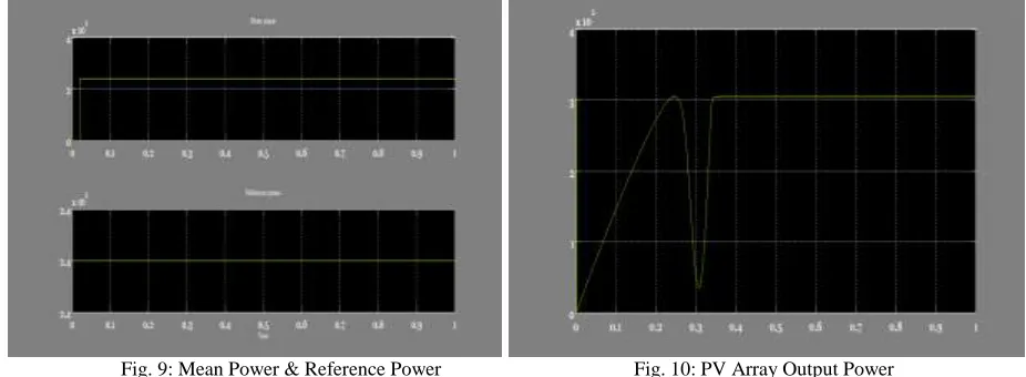
Fig. 9: Mean Power & Reference Power Fig. 10: PV Array Output Power
Fig. 7: is plotted as grid power of the system. As the reference power was 25 kW, but after the simulation when we checked the power available to the grid was around 23.994 kW, i.e. approx. 24 kW. So, the efficiency of the above designed grid connected system is approx. 93%. The wave form in fig. 8 shows graph between grid voltage and time, according to this graph we are getting per unit value of 0.95 V. Fig. 9 depicts the PWM duty cycle. Here, the mean power and reference power’s waveform has been shown with respect to time, mean power is 24 kW and continuous after 0.02 interval the reference power should be 24kW continuously. The waveform is useful in checking the mean power at each instant of time. Finally, the wave form in fig. 10 shows the output power of the PV array, power is around 3.1 kW, which is constant after 0.3 sec.
V. CONCLUSION
DC-DC converters and their design remain an interesting topic and new control schemes to achieve better regulation and fast transient response are continually developed. A key challenge to design switching regulators is to maintain almost constant output voltage within acceptable regulation. In this paper, MATLAB simulink is preferred over other software for its enhanced designing, modelling & manipulating features. The block diagram of the converter system in MATLAB simulates the functionality of the system while providing specification for each individual block. We concluded that, the grid-connected PV system examined under PI control of inverter, delivers power to the grid of about 24 kW. As the reference power of our proposed system, was 25 kW, so the calculated efficiency of the system is approximately 93%. The discussed modeling technique can be extended to enhanced inverter control schemes with controllers such as dead beat controller, proportional resonant controller, repetitive controller, modified ramp type controller for the improvement of efficiency of the designed grid connected PV system .
REFERENCES
[1] J.-H. Kim, J.-G. Kim, Y.-H. Ji, Y.-C. Jung, and C.-Y. Won, “An islanding detection method for a grid-connected system based on the goertzel algorithm,” IEEE Trans. Power Electron. , vol. 26, no. 4 , pp. 1049–1055, Apr. 2011.
[2] S. TheisKiran, Y. Vishnu Vardhan Reddy” One dimensional optimization for proportional-resonant controller against the change in solar irradiation and source impedance in PV system” Vol. 02, Issue 08,pp. 145-153, 8 Nov 2015.
[3] Cagnano, E. De Tuglie, M. Liserre, and R. A. Mastromauro, “Online optimal reactive power control strategy of PV inverters,” IEEE Trans. Ind. Electron., vol. 58, no. 10, pp. 4549–4558, Oct. 2011.
[4] Seena M Varghese,” Multilevel Inverter for grid-connected PV system employing MPPT & PI controller”,Vol.2,Special Issue 1,December 2013
[5] AvdhootaTrivedi,Asst. Prof. FalguniBhavsar,Asst. Prof. Ajay Balar,”Novel control strategy for grid-connected PV system with reactive power compensation and MPPT control” Vol. 2, Issue 5, May 2014
[6] KedarPatil,” Harmonics analysis of sine PWM and hysteresis current controller “, Vol. 2, Issue 11, November 2013
[7] Zameer Ahmad, S.N. Singh, “Modeling and Control of Grid Connected Photovoltaic System-A Review”, Vol. 3, Issue 3, March 2013
[8] Seena M Varghese “Multilevel Inverter for Grid-Connected PV SystemEmploying MPPT and PI Controller” vol. 2, special issue 1, December 2013 [9] Swaroop .R “ A case study on performance evaluation of grid connected PV generation system in UAE”, Vol. 3 Issue 12, December 2014
[10] Wenhao CAI, Hui REN “Research on Grid-Connected Photovoltaic System Based on Improved Algorithm”PRZEGLĄD ELEKTROTECHNICZNY (Electrical Review), ISSN 0033-2097, R. 88 NR 3b/2012
[11] G. Walker, “Evaluating MPPT converter topologies using a MATLAB PV model,” J. Elect. Electron. Eng., vol. 21, no. 1, pp. 49–56, 2001
[12] C Thulasiyammal, S. sutha, R renuga, “Performance Analysis of Converters using Solar Powered Maximum Power Point Tracking (MPPT) Algorithms” Vol. 1, issue 5, October 2015
[13] R.Anand, G.Ashok Kumar” A Multilevel Inverter for Grid Connected Photovoltaic System by employing PID Controller” vol. 2 , issue 1, October 2012. [14] HesanVahedi, Reza Noroozian, AbolfazlJalilvand, and Gevorg B. Gharehpetian, “A New Method for Islanding Detection of Inverter-Based Distributed
Generation Using DC-Link Voltage Control” IEEE TRANSACTIONS ON POWER DELIVERY, VOL. 26, NO. 2, APRIL 2011 [15] N.Hamrouni and A.Cherif,”Modelling & control of a grid connected PV system“Vol. 10, no. 3, pp. 335-344, 2007
[16] SittichaiKeawthai and Sakorn Po-Ngam, 24-27 June 2015 “Simplified Active Power and Reactive Power Controlwith MPPT and Islanding Detection for
Three-Phase Grid-Connected Photovoltaic Inverters” presented at 12th conference ECTICON [online], Available:
![Fig. 2: Flow Chart of P&O Algorithm [15]](https://thumb-us.123doks.com/thumbv2/123dok_us/7826209.1666064/3.612.54.555.523.676/fig-flow-chart-p-o-algorithm.webp)
![Fig. 4: Flow Chart of P&O Algorithm [15]](https://thumb-us.123doks.com/thumbv2/123dok_us/7826209.1666064/4.612.55.562.57.224/fig-flow-chart-p-o-algorithm.webp)