Real time Virtual View Generation For
Augmented Virtuality System
Yong Tang
Nanjing University of Aeronautics and Astronautics Nanjing, 210016, P.R.China Email: [email protected]
Hongbin Gu and Lai Zhou
Nanjing University of Aeronautics and Astronautics Nanjing, 210016, P.R.China Email: [email protected], [email protected]
Abstract—This paper describes a novel method of real-time virtual view generation for augmented virtuality system. The aim is to rectify the displacement between virtual eye position and video cameras which are attached on the head mounted display. It consists of three steps: Firstly, stereo calibration was used to generate cameras' internal and external parameters, and then image planes were rectified to canonical configuration state that made them alignment or corresponding points on the same scan lines. At last the virtual view images between two cameras are generated using view morphing which is a shape-preserving transition method from a source to a destination view. We can adopt this method to choose locations of two virtual cameras yielding an in-between stereoscopic camera views without reconstructing the 3D model of the object. The view of the object corresponding to a virtual camera that is located between two real cameras with same position of eyes. So we can control the feeling of depth and provide customized viewpoint to the user. It can be used in a variety of augmented virtuality applications to integrate live video objects into virtual environments. Experimental results verify the validity of the proposed approach, and we also show interlaced stereo composition results using a pair of synthesized views from input views acquired by stereo cameras.
Index Terms— view morphing, stereo calibration, stereo rectification, augmented virtuality
I. INTRODUCTION
The rapid progress in computer vision, computer graphics and enables the user to enter a realistic augmented virtuality (AV) space. When the user wearing video see-thru HMD in such systems, the real image is captured two cameras that processed in a computer (augmented data) is added on the images display, subjects which the user see around them are the fusion of real object (captured by carmeras) and virtual environment (generated by computer) [1]. Such as the Poser [2], a augmented virtuality system that integrating the hand image to virtual environment to enhance the presence in HMD environments by visual body feedback. Unfortunately, the cameras have the same position as eyes is impossible because of the limitation of the HMD's
physical structure in AV system. We have to set the virtual viewpoint in virtual environment consist with the cameras' position to ensure the correct registration in our system. In this case, it makes a displacement that between the real and virtual eye position, and this may cause uncoordination, uncertainty, and inaccuracy on the user’s body [3]. Although human brain is capable to adapt very fast when an immersive system is used, still there remains a problem when using the HMD after he adapted the reality. This is why the position of the cameras can not be ignored in our investigation. Currently, where to fix the camera are categorized as follow [4]:
z Placed each camera in front of each eye. It is adopted widely, but this includes that the seen images are closer and bigger as in reality, such as the poser which the paper mentioned.
z Place each camera next to each eye or above it. This has the disadvantage that it is not exactly the same view as with the eyes.
z Place the camera next to helmet and in front of the face pointing to a mirror which is with a 45 angle in front of the eyes. This give the user the same impression as viewing with his naked eyes, however the size of the mirror should be too big to place two of them and the construction gets to bulky.
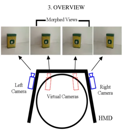
Figure 1. The overview of virtual view generation system two real cameras is generated in real-time based on view
morphing. Without recovering the 3D model of the object, the resulting novel view ensures a natural and a new virtual view image of the same position of eyes between the captured image pair. The proposed method can be used in various applications in AV system. For example, an object (e.g. the hand) that is captured in real-time by two video cameras in a natural environment can be integrated into a AV space (e.g. a virtual touch board), where the user is able to observe the new virtual view image in real-time during his/her interaction in the AV environment.
2.RELATEDWORKS
The methods for generating arbitrary view images from real camera images have been studied since the 1990s in the field of computer vision [7]. These techniques which are called Image Based Rendering (IBR) can be categorized into two groups, Model Based Approach and Transfer Based Approach. Model Based Approach constructs a 3D shape model of an object to generate the desired view [8, 9]. Since the quality of the virtual view image depends on accuracy of the 3D model, a large number of video cameras surrounding the target object or range scanners are used for construction of an accurate model. Also strong camera calibration, which is carried out to relate 2D coordinates in images to 3D coordinates in object space, is usually required. As 3D positions of several points in the object space must be measured, this calibration becomes difficult especially in a large space. For such reasons, the object area is generally limited within a few cubic meters in this approach. On the other hand, Transfer Based Approach synthesizes arbitrary view images without an explicit 3D model [10]. Instead, image warping such as transfer of correspondence is employed for synthesizing new view images. The dense correspondence between the original images, which is required for view-synthesis, is often obtained manually or by the use of optical-flow, so almost all targets are static images or slightly varying images such as facial expression. Thus we have proposed view-synthesis method targeting dynamic events in our paper to replace the position of the camera, which is included in Transfer Based Approach [11, 12]. As for arbitrary view presentation, A related approach to our method has been proposed in [13, 14]. Naho Inamoto described a new framework for arbitrary view synthesis and presentation of sporting events for mixed reality entertainment. Virtual view image of sporting scene is generated by view interpolation among multiple videos captured at real stadium. The user can watch the superimposed images of a remote collaborator in the real world. Hua Chen described a novel method of real-time novel view synthesis for an object that is observed by two fixed video cameras in a natural environment. In above system, the object was remote captured and should use user input for post-warping. In addition, the generated in-between views are much affected by self-occlusion. One advantage of our method is based on projective geometry between two cameras instead of reconstructing 3D
models.
3.OVERVIEW
Figure 1 shows overview of the proposed method. A video see-through HMD is used for AV environment. An observer sees the views of two virtual cameras which are generated by the real cameras that attach next to the HMD, so the virtual viewpoint can keep the same position of eyes in AV environment.
In order to generate novel new views, three step was implemented as follow.
z Calibrate the pair of cameras. z Rectification the of pair cameras
z Generate new virtual images between two pair cameras
Step (1) is process of computing the geometrical relationship between the two cameras in space. In contrast, Step (2) is the process of “correcting” the individual images so that they appear as if they had been taken by two cameras with row-aligned image planes. With such a rectification, the optical axes of the two cameras are parallel and so we say that they intersect at infinity. At the step (3), neighboring cameras near the viewpoint position, which are reference cameras, synthesize the virtual viewpoint image of the new view by linear interpolation. At the final stage, synthesized object scene is overlaid on virtual environment. The observer can virtually watch AV environment from favorite viewpoints in the system.
4.CALIBRATION OF TWO CAMERAS
Figure 2. Planar Pattern in Zhang’s Calibration Method
Stereo calibration is the process of computing the geometrical relationship between the two cameras in space, which depends on finding the internal parameter, the rotation matrix R and translation vector T between the two cameras, and then we can calculate essential matrix, fundamental matrix and so on. In this paper, we calibrated two cameras based on the Zhang Plane-based Calibration Method which proposed a flexible camera calibration technique by replacing expensive classical calibration grid with a planar pattern for single camera [15]. A print sheet (see figure 2) as the model plane, and the Euclidean coordinates of every dot on the model plane should be measured accurately. After taking a few images of the model plane at different orientations by moving either the model plane or the camera, the homographies between the model plane and its projections can be determined, and then camera’s intrinsic parameters can be derived linearly from these homographies. Zhang’s technique is flexible and low-cost, its accuracy is generally higher than self-calibration.
The basic steps of this method are as follows: print a chessboard pane picture and paste it on a plane, shoot more than 3 model images from different angels, detect the feature points from every image, calculate the plane projection matrix H for every image through the detected points, at last determine the parameters of camera.
Supposed that the model plane coincides with the plane in the world coordinate system where Z =0. K indicates the internal parameter matrix of the camera,
is the vector of R, for every point in the model plane we have i r th i
[
]
[
]
⎥ ⎥ ⎥ ⎦ ⎤ ⎢ ⎢ ⎢ ⎣ ⎡ = ⎥ ⎥ ⎥ ⎥ ⎦ ⎤ ⎢ ⎢ ⎢ ⎢ ⎣ ⎡ = ⎥ ⎥ ⎥ ⎦ ⎤ ⎢ ⎢ ⎢ ⎣ ⎡ 1 1 0 1 3 2 1 3 2 1 Y X r r r K Y X r r r K v us (1)
Let , so we get a homography H
between the point in model plane and its corresponding image point, if known the coordinate of the point in model plane, we can compute the homography
[
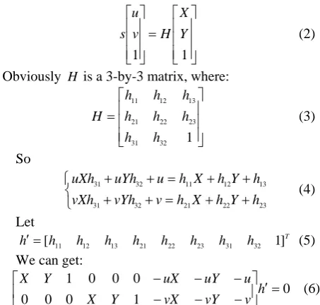
r1 r2 r3H = ⎥ ⎥ ⎥ ⎦ ⎤ ⎢ ⎢ ⎢ ⎣ ⎡ = ⎥ ⎥ ⎥ ⎦ ⎤ ⎢ ⎢ ⎢ ⎣ ⎡ 1 1 Y X H v u
s (2)
Obviously H is a 3-by-3 matrix, where:
⎥ ⎥ ⎥ ⎦ ⎤ ⎢ ⎢ ⎢ ⎣ ⎡ = 1 32 31 23 22 21 13 12 11 h h h h h h h h
H (3)
So ⎩ ⎨ ⎧ + + = + + + + = + + 23 22 21 32 31 13 12 11 32 31 h Y h X h v vYh vXh h Y h X h u uYh uXh (4) Let T h h h h h h h h
h′=[ 11 12 13 21 22 23 31 32 1] (5)
We can get:
0 1 0 0 0 0 0 0 1 = ′ ⎥ ⎦ ⎤ ⎢ ⎣ ⎡ − − − − − − h v vY vX Y X u uY uX Y X (6)
Then we can detect some feature points in one image, then we have Sh′=0 ugh computing these equations by using least square method, we can get h
, thro
′ andH . Afte enerating the homography matrix, the next step is to compute the internal parameter.
r g
Define every row of H as hi, then
[
h1 h2 h3]
=λK[
r1 r2 t]
(7) Because and are orthonormal, there are two constraints:1
r r2
0 2 1 1 = − − h K K
hT T
(8) 2 1 2 2 1
1K K h h K K h
hT −T − = T −T −
(9)
Set = − −1
M M
B T
Writing this out, we have:
⎥ ⎥ ⎥ ⎦ ⎤ ⎢ ⎢ ⎢ ⎣ ⎡ = − − 33 23 13 23 22 12 13 12 11 1 B B B B B B B B B K K B T (10)
matrix B has a general closed-form solution:
⎥ ⎥ ⎥ ⎥ ⎥ ⎥ ⎥ ⎥ ⎦ ⎤ ⎢ ⎢ ⎢ ⎢ ⎢ ⎢ ⎢ ⎢ ⎣ ⎡ + + − − − − = 1 1 0 0 1 2 2 2 2 2 2 2 2 y y x x y y x x y y y x x x f c f c f c f c f c f f c f
B (11)
Using the B-matrix, both constraints have the general form T
in them. Let’s multiply this out to see what the components are. Because B is symmetric, it can be written as one six-dimensional vector dot product. Arranging the necessary elements of B into the new vector b, we have:
j l Bh h
]
⎥ ⎥ ⎥ ⎥ ⎥ ⎥ ⎥ ⎥ ⎦ ⎤ ⎢ ⎢ ⎢ ⎢ ⎢ ⎢ ⎢ ⎢ ⎣ ⎡ ⎥ ⎥ ⎥ ⎥ ⎥ ⎥ ⎥ ⎥ ⎦ ⎤ ⎢ ⎢ ⎢ ⎢ ⎢ ⎢ ⎢ ⎢ ⎣ ⎡ + + + = = 33 23 13 22 12 11 3 3 3 2 2 3 3 1 1 3 2 2 1 2 2 1 1 1 B B B B B B h h h h h h h h h h h h h h h h h h b v Bh h j i j i j i j i j i j i j i j i j i T ij j T
i (12)
Using this definition for , our two constraints may now be written as:
T ij v
(
)
022 11 12 = ⎥ ⎦ ⎤ ⎢ ⎣ ⎡
−v b
v v
T T
(14)
If there are n images, we have such equations through 0
=
Vb (15) Where V is a 2n× 6 matrix. We can calculate b and B from (18). The internal parameters can be obtained by using Choleski decomposition.
11
/B
fx = λ
) /( 2
12 22 11 11 B B B
B
fy= λ − λ
/
2 13 x
x B f
c =−
(15) ) /( ) ( 2 12 12 11 23 11 13
12B B B B B B
B
cy = − −
Where: 11 23 11 13 12 2 13
33 c (B c (B B B B ))/B
B − y + y −
= λ
Where V is a 2K-by-6 matrix. As before, if K >=2
then this equation can be solved for he camera intrinsic parameters are then pulled directly out of our closed-form solution for the B-matrix:
[
B11 B12 B22 B13 B23 B33]
b= . T
1 1
1 K h
r =λ −
2 1
2 K h
r =λ −
2 1 3 r r
r = ×
3 1
h K
t=λ − (16) Here the scaling parameter is determined from the orthonormality condition 1
1
/ 1 K−h =
λ .
5.RECTIFICATION OF TWO CAMERAS
The goal of rectification is to reproject the image planes of two cameras to ensure them reside in the exact same plane, with image rows perfectly aligned into a frontal parallel configuration. The rotation matrix and translation matrix (R, T) between the stereo images are generated in section 4, So we can make use of Bouguet’s algorithm[16] for stereo rectification simply attempts to minimize the amount of change reprojection produces for each of the two images (and thereby minimize the resulting reprojection distortions) while maximizing common viewing area.
In order to minimize image reprojection distortion, the rotation matrix R that express the rotation between the right camera’s image plane and the left camera’s image plane is split in half between the two areas, respectively. In our method, each camera rotates half a rotation of R, so their principal rays each end up parallel to the vector
sum of where their original principal rays had been pointing. Such a rotation puts the cameras into coplanar alignment but not into row alignment. To compute the matrix that will take the left camera’s epipole to infinity and align the epipolar lines horizontally, we create a rotation matrix by starting with the direction of the epipole itself. Taking the principal point
rect R
1
e
(
cx,cy)
asthe left image’s origin, the direction of the epipole is directly along the translation vector between the two cameras’ centers of projection:
T T
e1= (17)
The next vector must be orthogonal to but is otherwise unconstrained. For , choosing a direction orthogonal to the principal ray is a good solution. This is accomplished by using the cross product of with the direction of the principal ray and then normalizing so that we can get another vector:
2
e e1
2 e 1 e
[
]
2 2 2 0 y x x y T T T T e + −= (18)
The third vector is just orthogonal to and ; it can be found using the cross product:
1
e e2
2 1 3 e e
e = ×
Our matrix that takes the epipole in the left camera to infinity is then:
⎥ ⎥ ⎥ ⎦ ⎤ ⎢ ⎢ ⎢ ⎣ ⎡ = T T T rect e e e R ) ( ) ( ) ( 3 2 1 (19)
This matrix rotates the left camera about the center of projection so that the epipolar lines become horizontal and the epipoles are at infinity. The row alignment of the two cameras is then achieved by setting:
l rect
l R r
R = , Rr =Rrectrr (20) Then We can also compute the rectified left and right camera matrices and but return them
combined with projection matrices and : l
rect
M _ Mrect_r
l
p pr
⎥ ⎥ ⎥ ⎦ ⎤ ⎢ ⎢ ⎢ ⎣ ⎡ ⎥ ⎥ ⎥ ⎦ ⎤ ⎢ ⎢ ⎢ ⎣ ⎡ = ′ = 0 1 0 0 0 0 1 0 0 0 0 1 1 0 0
0 _ _ _ _
_ y f y l
l x l f x l t rect
l f c
c a f
P M
P (21)
and ⎥ ⎥ ⎥ ⎦ ⎤ ⎢ ⎢ ⎢ ⎣ ⎡ ⎥ ⎥ ⎥ ⎦ ⎤ ⎢ ⎢ ⎢ ⎣ ⎡ = ′ = 0 1 0 0 0 0 1 0 0 0 0 1 1 0 0
0 _ _
_ _
_ y f y l
l x l f x r t rect
r f c
c a f
P M
P (22)
The projection matrices take a 3D point in homogeneous coordinates to a 2D point in homogeneous coordinates as follows:
Where the screen coordinates can be calculated as . Points in two dimensions can also then be reprojected into three dimensions given their screen coordinates and the camera intrinsic matrix. The reprojection matrix is:
) / , / (x w y w
⎥ ⎥ ⎥ ⎥ ⎥
⎦ ⎤
⎢ ⎢ ⎢ ⎢ ⎢
⎣ ⎡
− −
− −
=
x y x x
y x
T c c T
f c c
Q
/ ) ( / 1 0 0
0 0 0
0 1 0
0 0 1
(24)
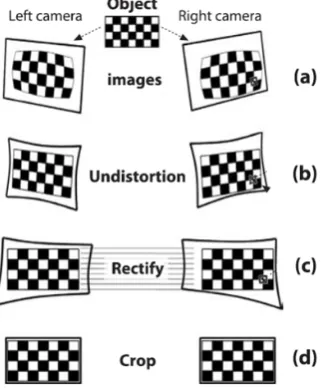
Figure 3. The process of stereo rectification
Figure 4. Morphing Parallel Views. Linear interpolation of corresponding pixels in parallel views
Here the parameters are from the left image except for cx , which is the principal point x coordinate in the right image. If the principal rays intersect at infinity, then and the term in the lower right corner is 0. Given a two-dimensional homogeneous point and its associated disparity d, we can project the point into three dimensions using:
x x c c = ′
⎥ ⎥ ⎥ ⎥
⎦ ⎤
⎢ ⎢ ⎢ ⎢
⎣ ⎡
= ⎥ ⎥ ⎥ ⎥
⎦ ⎤
⎢ ⎢ ⎢ ⎢
⎣ ⎡
W Z Y X
d y x
Q
1
(25)
Once we have our stereo calibration parameter, we can compute left and right rectification lookup maps for the left and right camera views separately. As with any image-to-image mapping method, a forward mapping (in which we just compute where pixels go from the source image to the destination image) will not, owing to floating-point destination locations, hit all the pixel locations in the destination image. So instead we work backward: for each integer pixel location in the destination image, we look up what floating-point coordinate it came from in the source image and then interpolate from its surrounding source pixels a value to use in that integer destination location. This source lookup typically uses bilinear interpolation. The process of rectification is illustrated in Figure 3 [17].
6.VIEW GENERATION OF IN-BETWEEN VIEWS BY VIEW MORPHING
In this section, we explain the algorithm of in-between view synthesis for the object images. We used the view interpolation based view morphing [18] between neighboring cameras near the virtual viewpoint position generates virtual view images of object image for each frame real time.
Suppose is a photograph of an object, and is a second picture, as shown in figure 4.
0
I I1
Alternatively, we could produce the same two images by moving the camera instead of the object. Linear image interpolation could produce new perspective views when the camera moves parallel to the image plane. Indeed, suppose that the camera is moved from the world origin to position
(
CX,CY,0)
and the focal length changes from to . We write the respective projection matrices,0
f f1
0
∏ and∏1, as:
⎥ ⎥ ⎥
⎦ ⎤
⎢ ⎢ ⎢
⎣ ⎡ = ∏
0 1 0 0
0 0 0
0 0 0
0 0
0 f
f
(26)
⎥ ⎥ ⎥
⎦ ⎤
⎢ ⎢ ⎢
⎣ ⎡
− − =
∏
0 1 0 0
0 0
0 0
1 1
1 1
1 Y
X C f f
C f f
(27)
Let p0∈I0 and p0∈I1 be projections of a scene point
[
]
TZ Y X
P= 1 . Linear interpolation of and yields:
0
p
1
p
( )
PZ P Z s P Z s sp p
s + = − ∏ + ∏ = ∏s
− (1 )1 1 1
1 0 1 0 0 (28)
Where
1 0
) 1
( − ∏ + ∏
=
∏s s s (29) Image interpolation therefore produces a new view whose projection matrix ∏s, is a linear interpolation of
0
∏ and ∏1, representing a camera with center and
focal length given by:
s C
s f
) 0 , ,
( X Y
s sC sC
Figure 5. Synthesizing stereoscopic view based on view morphing
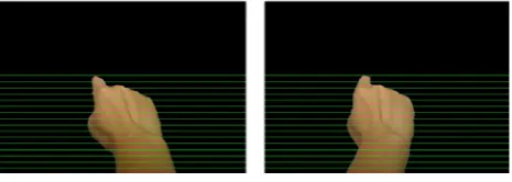
Figure 6. Hand images before calibration and rectification
1 (30) 0
) 1
( s f sf
fs= − +
Figure 7. Hand images after calibration and rectification. Consequently, interpolating images produced from
parallel cameras produces the illusion of simultaneously moving the camera on the line C0C1 between the two
optical centers and zooming continuously. Because the image interpolation produces new views of the same object, it is shape-preserving.
To obtain an in-between stereoscopic view we firstly choose proper positions of the virtual stereo camera between two cameras. Firstly, We set two virtual stereo cameras and between the origins of the first camera and the second camera . The positions of the virtual cameras are defined based on the distance between eyes respectively as shown in figure 5.
l
C Cr
0
C C1
Once we choose the linear interpolation parameters, and , we can generate stereoscopic images, and , whose camera centers are and .Each coordinate of a point and can be defined by
l
s sr Il Ir
l
C Cr
l l I
p ∈ pr∈Ir
1 | 0 |
| (1 s )p s p
plr= − lr + lr (31)
Where , are the corresponding points in and , and . For a convenience, we use ‘|’ meaning ‘or’, for example represents or .
0
p p1 I0
1
I 0≤sl|r ≤1
r l
p| pl pr
Each pixel value of can be defined by forward
mapping [19] using the and , which yields ,and
as
r l I|
0
I I1 Il|r,0
1 , |r l I
) )), , ( ( ) 1 (( )
,
( |,0 | | 0
0 u v I s u s u d u v v
I → lr − lr + lr −
) , )) , ( )( 1 (( )
,
( |,1 | 1 |
1 u v I s u d u v s u v
I → lr − lr + + lr (32)
Whered01| is a disparity map of the I01|.
In case of holes caused by disordered area in both and [20], linear interpolation of the neighborhood pixels can be used to define a pixel value of the area. In other cases, by refering two intermediate images and
by (33), we can generate the stereoscopic images
and which do not have any holes caused by disordered area from one view.
0
I I1
0 , |r l I
r l I|
l
I Ir
⎪ ⎩ ⎪ ⎨ ⎧
+ −
=
) (otherwise
) , ( )
, ( ) 1 (
) hole a ) , ( ( ) , (
) hole a ) , ( ( ) , ( )
, (
1 , | | 0
, | |
0 , | 1
, |
1 , | 0
, | |
v u I s v u I s
is v u I if v
u I
is v u I if v
u I
v u I
r l r l r
l r l
r l r
l
r l r
l
r l
(33)
7.EXPERIMENTALRESULTS
For experimental verification, We have implemented a AV system for testing. Equipments include HMD (VR1280), two cameras, a conventional PC (with 2.2GHz CPU, 2GB RAM) were present. The users' hand that was placed in front of HMD has been integrated into an AV space. The captured videos are composed of 640*480 pixels, 24-bit-RGB color images. Our goal was to generate new virtual view of hand image which captured by cameras and then integrated them into the virtual environment to make an optimal viewpoint for user. The
approach to segment the user’s foreground hand from the background in the camera images was used the skin detection algorithmic [20]. The stereo hand images were showed in figure 6.
Firstly, two cameras were calibrated and rectified to canonical configuration state that made the image planes
alignment or corresponding points are on the same scan line. Figure 7 shows the source images and images after our process.
Figure 8. Arbitrary views between the pair cameras
In our AV system, the distance between cameras is about 160mm (the width of HMD), and the distance between people's eyes are about 65mm. We can compute the distance weights ( , ). So the left image and right image the user saw were as Fig 9 shows.
3 . 0 =
l
s sr =0.7
Figure 9. Images that the user saw in HDM
Compared to the source image in figure 6, the results show that we can control the viewpoint of the stereoscopic view but also the screen parallax by choosing different eye separation(distance between eyes), which gives us different levels of depth perception.
8.CONCLUSIONS
This paper presents a novel method to generate novel views of an object that is placed in an AV environment real-time. Without 3D knowledge of the object, the novel view is generated by transforming live video frames captured by two fixed real cameras. The proposed method results in realistic novel views of the object corresponding to a virtual camera that have same position of user's eyes between two real cameras. Besides, the proposed method enables to provide any viewpoint between input views and the different level of depth perception by adjusting the distance between two virtual cameras.
Proposed method also has limitations. Firstly, since it relies on the dense correspondence between two input views, results tend to be sensitive to noisy. The other
limitation is that information of the occluded area from both input images cannot be recovered resulting in holes. Therefore, appropriate hole filling algorithm for both disparity maps and input images should be supported.
8.ACKNOWLEDGMENT
The authors wish to thank anonymous reviewers for giving helpful suggestions. This work is supported by the National High Technology Research and Development Program of China under Grant No. 2007AA01Z306, and the National Nature Science Foundation of China under Grant No. 60776812.
REFERENCES
[1] A. M. HAO, B.HE, Q. P. ZHAO, "Review of augmented virtuality technology in virtual reality," Journal of Beijing University of Aeronautics and Astronautics, vol.29, no. 10, pp. 909-913, 2003
[2] B. Gerd; S. Frank; R. Kai; H. Klaus, "Enhancing Presence in Head-mounted Display Environments by Visual Body Feedback Using Head-mounted Cameras," Proc of 2009 International Conference on CyberWorlds, pp. 43-50 IEEE Computer Society, September, 2009.
[3] J. P. Roland, F. A. Biocca, T. Barlow, and A. Kancherla, "Quantification of adaptation to virtual-eye location in see-thru head-mounted displays," Proc of the Virtual Reality Annual International Symposium, pp. 56-66, IEEE Computer Society, 1995.
[4] R. Azuma, Y. Baillot, R. Behringer, S. Feiner, S. Julier, and B. MacIntyre, “Recent Advances in Augmented Reality,” IEEE Computer Graphics and Application, vol. 21, no. 6, pp. 34-47, Nov. 2001
[5] C. Eddie1, K, Peter, S, Thomas, "Multi-view synthesis: A novel view creation approach for free viewpoint video," Signal Processing: Image Communication, vol. 21, no. 6, pp.476-492, July, 2006
[6] S. M. Seitz and C. R. Dye, "View morphing," IEEE Transactions on Image Processing, vol. 6, no. 4, pp.584 -598, April, 1997.
[7] H. Saito, S. Baba, and T. Kanade, "Appearance-basedvirtual view generation from multicamera videoscaptured in the 3-d room". IEEE Trans. onMultimedia, vol.5, pp.303–316, September 2003.
[8] S. M. Seitz and C. R. Dyer. "Photorealistic scenereconstruction by voxel coloring," Proc of. ComputerVision and Pattern Recognition, pp.1067–1073, January 1998.
[9] M. D. Wheeler, Y. Sato, and K. Ikeuchi. "Consensus surfaces for modeling 3d objects from multiple range images". DARPA Image Understanding Workshop, pp.917-923, 1997.
[10]S. Avidan and A. Shashua. Novel view synthesis by cascading trilinear tensors. IEEE Trans. On Visualization and Computer Graphics, vol.4, pp.293–306, April, 1998. [11]N. Inamoto and H. Saito. "Fly through view
videogeneration of soccer scene". International Workshop on Entertainment Computing Workshop Note, pp.94–101, May 2002.
[12]N. Inamoto and H. Saito, "Intermediate view generation of soccer scene from multiple videos". Proc of International Conference on Pattern Recognition, pp.713–716, August 2002.
Entertainment," Proc of ACM International Conference Series, vol.74, pp.42-50, ACM Press, 2004.
[14]H. Chen, P. F. Elzer, "Novel View Generation for A Realtime Captured Video Object," Proceedings of the ACM symposium on Virtual reality software and technology, pp.83-86, 2006.
[15]Z.Y.Zhang. "Flexible Camera Calibration by Viewing a Plane from Unknown Orientations," Proc of IEEE International Conference on Computer Vision, pp. 666-673, IEEE Computer Society Press, 1999.
[16]J.Y. Bouguet, “Camera calibration toolbox for Matlab,” [17]G. Bradski and A. Kaehler, "Learning OpenCV" O'Reilly
Media press, Sebastopol, 2008
[18]S. M. Seitz and Charles R. Dye, "View morphing," Proc of SIGGRAPH. pp.21-30, 1996.
[19]A. Criminis, A. Blake, C. Rother, J.Shotton: “Efficient dense stereowith occlusions for new view-synthesis by four-state dynamic programming”. International Journal of Computer Vision vol.71, pp. 89–110, 2007.
[20]S.E. Chen, L. William: View interpolation for image synthesis. In: Proc of 20th Annual Conference on Computer Graphics and Interactive Techniques, pp. 279– 288. ACM Press, New York 1993.
[21]C. Tsai ,A. K. Katsaggelos, "Dense disparity estimation with a divide-andconquer disparity space image technique," IEEE Transactions on Multimedia, vol.1, no.1, pp.18-29, 1999
[22]Y. TANG, H. B GU, L. ZHOU, "Real-time Hand Segmentation and Fingertip Detection for Interaction,"
Opto-Electronic Engineering, vol.37 no.7, pp.145-150. 2010.
Yong Tang was born in Yiyang, Hunan province China in 1983. He is currently a Ph.D. candidate at Nanjing University of Aeronautics and Astronautics, Nanjing, China, and his research interests include virtual reality, image processing, etc.
HongBin Gu was born in Changzhou, Jiangshu province China in 1955 and received the doctor's degree from Nanjing University of Aeronautics and Astronautics, Nanjing, China in 2000. He is currently an associate professor at Nanjing University of Aeronautics and Astronautics. His main research interest is include flight simulation, virtual reality, image processing, etc.