Dynamic Module Library for System Level
Modeling and Simulation of Dynamically
Reconfigurable Systems
Kenji Asano
NEC Electronics Corporation 1753, Shimonumabe, Nakahara-Ku, Kawasaki, Kanagawa 211-8668, JAPANEmail: [email protected]
Junji Kitamichi Kenichi Kuroda School of Computer Science and Engineering,
The University of Aizu, Tsuruga, Ikki-machi, Aizu-Wakamatsu,
Fukushima 965-8580, JAPAN Email:{kitamiti,kuroda}@u-aizu.ac.jp
Abstract— In this paper, we propose a library for the system level modeling and simulation of the system which includes Dynamically Reconfigurable Architectures(DRAs). The proposed library is an extended SystemC library. Using the proposed library, the designer can model the system specifications including modules for the dynamic generation and elimination and ports and channels for the dynamic connection and dispatch between them, that are needed in the design of general-purpose dynamically reconfigurable systems at the system design level. In addition, we evaluate the proposed library by the modeling and simulation of sample circuits, such as partially DRA and multi-context DRA. Using the proposed library, we can model the system specifications naturally, and as much the same amount as a description, such as one using multiplexers and de-multiplexers, which is a modeling formula for describing multi-context DRA. Under some conditions, higher-speed simulation is possible using the proposed library.
Index Terms— system level design, dynamically reconfig-urable architectures, SystemC
I. INTRODUCTION
The progress of LSI processing technology has led to the development of a large-scale system on a single chip, such as System on a Chip (SoC) [1]. An SoC is constructed with CPUs, DSPs, memories and Application Specific Integrated Circuits(ASICs). However, the time
This paper is based on “Proposal of Dynamic Module Library for System Level Modeling and Simulation of Dynamically Reconfigurable Systems,” by K.Asano, J. Kitamichi, and K. Kuroda, which appeared in the Proceedings of the 20th International Conference on VLSI Design (VLSID’07), Bangalore, India, Jan. 2007. c2007 IEEE.
and costs required for design and verification are increas-ing. To circumvent these disadvantages, the following design methodologies are being proposed.
One is a system level design. The abstraction level of system level design is higher than that of traditional Register Transfer (RT) level. In the traditional design flow, system specifications are written in a natural lan-guage. Therefore, they may contain vague statements and mistakes. This causes problems in the RT level design. Furthermore, a natural language cannot be converted to hardware and embedded software descriptions. Currently, some modeling languages are being proposed for system level design, such as SystemC [2] [3], SpecC [4], and SystemVerilog [5]. One of the advantages of some system level design languages that are based on C or C++, such as SystemC and SpecC, is that they can be easily translated to embedded software and some EDA tools can be used to synthesize them from the description in C into HDLs. In the system level design, the system description is divided into hardware and software specifications, and the hardware specification is synthesized into the RT level specification.
a specific design language, such as extended C language, and CAD tools for circuit design. Then, the design of a flexible system and the shortening of the design period are achieved.
However, because of a specific design language and CAD tools for circuit design, a designer cannot retarget a circuit to other DRAs. In the future, a modeling method for DRAs at the system level will be required, in which the designer focuses on the abstract behaviors of dynam-ically reconfigurable systems (DRSs).
In this paper, we propose a design methodology for general-purpose DRSs at the system level, which is independent of a specific DRA. We extend a library in SystemC for the modeling of DRSs at the system level. The extension provides dynamic generation and elimination for modules and the dynamic connection and dispatch for ports and channels. We evaluate the proposed library using the modeling and simulation of sample circuits, such as multi-context DRAs and partially DRAs. Using the proposed library, we can model the system specifications naturally, and as the same amount as a detailed descriptions, similar to one using multiplexers and de-multiplexers, which is a modeling formula for describing multi-context DRAs. Under some conditions, a higher-speed simulation is possible using the proposed library.
II. BACKGROUND A. System Modeling using SystemC
SystemC [2] is a system description language. SystemC has the ability for system modeling using a class library of C++. System models from the abstraction level to RT level can be described in SystemC, and they can be simulated at different levels.
In the RT level design, the system is modeled in Hardware Description Languages(HDLs), such as Ver-ilogHDL and VHDL, and the system is simulated using the simulator, such as NCVerilog by Cadence Design Systems. The increase of scale of the system has led to the huge simulation time. Using SystemC, we can model a system at the more abstract design level than the existing RT level, then faster simulation, the system profiling and analysis of the model enable. The model in SystemC can be simulated using SystemC Class Library by Open SystemC Initiative (OSCI) and C/C++ compiler or SystemC simulator and analysis environments by some vendors.
An event-driven simulation is the simulation core of SystemC. It controls the execution of processes according to the events. Primitive channels are defining channels, which are models of communication routes between mod-ules. For example, sc signal is a model of wire; events happen whenever the value of sc signal is changed. Sc fifo is a model of the FIFO channel.
The behaviors of parts of the system are described in the modules, and the channels connect each port. In the module, the declaration of ports, inputs and outputs of the modules, the definition and initialization of processes that
are behaviors of the module, the generations of instances of modules, and the binding with ports in the sub-modules to channels, are described. The sub-modules are defined by inheriting the sc module class, a class library of SystemC. Communication paths between modules are used in the channel. Inputs and outputs of modules are defined as ports, and the module communicates external modules through ports. The ports are bound to channels or the port of other modules before simulation starts and are never released and bound again.
Processes are defined as the behaviors of a module. When an event occurs, the processes that are correlated with the event are executed one by one. A channel or event is used for communication between processes in the same module. These processes are defined in the constructor of modules. They are initialized only at start of simulation and are never generated or eliminated during the simulation.
The idea of a dynamic process is added in SystemC 2.1.v1. It is possible to activate the dynamic process after the simulation has started. The dynamic process is designed to describe test benches or modeling of software. The sc spawn() method is used for the dynamic process. Static processes are initialized before the simulation starts, otherwise dynamic processes can be initialized anytime.
B. Dynamically Reconfigurable Architectures
Dynamically Reconfigurable Architectures(DRAs) can reconfigure own configuration while the system is op-erating. There are two types of DRAs, i.e., fine-grain and coarse-grain. Reconfigurable units of fine-grain ar-chitectures are constructed by Look Up Tables(LUTs) that use memory technology. LUTs can be constructed as any function, so every region can be efficiently used. On the other hand, ALUs construct reconfigurable units of coarse-grain architectures, therefore, they can compute numerical operations faster than fine-grain architectures. However, some reconfigurable units cannot be utilized, and the usage of the area is worse.
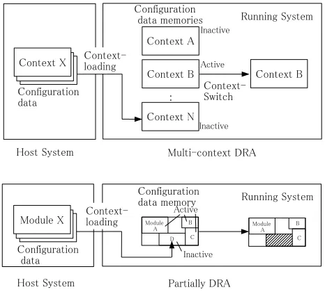
Multi-context DRA [7] [9] and partially DRA [8] [10] [11] make up one of classifications of DRAs, which are shown in Figure 1. Multi-context DRAs have some configuration data memories, which are called as con-texts, and the circuits are reconfigured by switching the contexts. The switching of the context takes place at once. To cover the cost of the reconfiguration, the contents of unused configuration memories can be downloaded from host system, and can be rewritten. In the partially DRA, the reconfiguration of circuits corresponds to the rewriting the configuration data in some areas. The modules at the areas of which configuration data are rewrote, stalls and the other modules continue running.
Figure 1. Outline of two types of DRAs
synthesis tool for the target device; therefore, a designer cannot retarget a circuit to other DRAs.
In the future, a modeling method for general purpose dynamically reconfigurable systems (DRSs) including a new DRA or several types of DRAs, at the system level will be required, in which the designer focuses on the abstract behaviors of DRSs.
III. PROPOSEDMETHODS
We describe the extended library for SystemC. The proposed library is extended for system level design, espe-cially the Dynamically Reconfigurable Systems (DRSs). In the DRS, modules are generated or eliminated while the system is running. In order to express these behaviors naturally at the system level design, modules have to be generated or eliminated dynamically and ports and chan-nels have to be connected and dispatched dynamically.
However, the generation and elimination of modules and the connection and dispatch of ports and channels cannot be performed after simulation has started, even if SystemC2.1.v1 is used.
We then propose a dynamic module library, which includes a dynamic module, a dynamic port, and a channel pool to solve these problems. In addition, profiling func-tions, such as the recording of the life times of dynamic modules, are implemented in the proposed library.
Some modeling methods for DRSs using SystemC have been proposed. The method proposed in [12] has some constraints on the modeling, such that all modules must be at the same level of hierarchy and instantiated in the same component. The target modeling class in [13] and [14] is more limited than our proposed method.
A. Dynamic Module
The dynamic module library enables the generation and elimination of module instances during the simulation.
Static modules, which are the conventional modules in SystemC, can be generated as the instances of modules only before the simulation starts. If the proposed library is used in modeling at the system level, the dynamic module class, which collects functions, such as newmod() and
delmod(), for the dynamic module, which are methods
to generate and eliminate the module respectively, is used rather than the sc module class, which is used in the declaration of the conventional modules in SystemC. Using the dynamic module class makes it possible to generate or eliminate modules after the initialization of the simulation. The proposed library is implemented on the basis of the dynamic process library.
User processes, which are described as functions of the module, and the spawn control process, which manages the user process, are defined in the dynamic module. The functions of the dynamic module library are as follows. If instances of the dynamic module are gener-ated, the spawn control process for the management of user processes is generated. The spawn control process switches the user processes according to a deleting request event or a behavior at the internal state. The generation of the dynamic process, such as the user process and
spawn control process, is used as a sc spawn function,
which is one of the Application Program Interfaces(APIs) of SystemC 2.1.v1.
On the other hand, there is no API for the elimination of the dynamic process; therefore, each dynamic process requires the judgment of the process termination. The elimination of the processes in the dynamic module is shown in Figure 2. If a deleting request event is received, the dynamic module has to stop the user processes and release the resources. In order to stop the thread-type processes, it gets out of while(true) loop. The deleting request event is notified of the event by spawn control process.
Figure 2. A Control for the Elimination in Dynamic Module Library
In the proposed library, only thread-type process can be used as the user process. Because an event that triggers the running a method-type dynamic process cannot be deleted at SystemC once it has been generated. Therefore, a method-type dynamic process cannot be used as a user process using dynamic module library.
can be described, which is equivalent to one in the style of the method-type.
The behaviors of the generation/elimination period of each dynamic module, such as the context loading from outside system, the initialization of configuration, the initialization of each register, and the swap-out of the results of computation or the contents of each register on the reconfiguration of modules, should be expressed in the modeling of a DRS. In addition, error-handling behaviors during a dynamically reconfiguration should be expressed. Therefore, to model them, a dynamic module in the proposed library has three predefined states: creating,
running and deleting. The operation of each state is
conducted in the “creating”, “running”, and “deleting” processes.
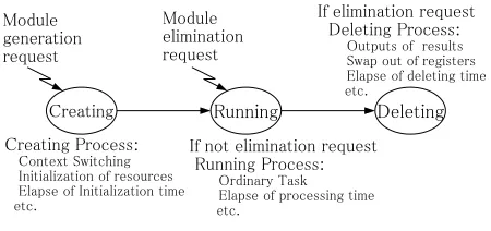
At the ”creating” state, the behaviors, such as the context switching or loading, the module and ports gen-erations, the connection between ports and channels, the initialization of system resources, the notification of initialization completion, the error handing, and the elapse of initialization time, are described as the user process, according to the needs. At the ”running” state, the behav-iors, such as the input/output of data, ordinary task for these data, the error handling, and the elapse of running time for the task, are described as the user process. At the ”deleting” state, the behaviors, such as the output of results, the swap-out of the contents of registers, the dispatch between ports and channels, the elimination of module and ports, the notification of elimination, the error handling, and the elapse of deleting time, are described as the user process. The control of state transitions is implemented in the spawn control of the dynamic module class. The state diagram of these processes in the dynamic module is shown in Figure 3.
The designer can describe the behaviors of each state as the user processes. In addition, the designer describes a creating time and a deleting time as the parameters of dynamic modules, those are dependent on the size of modules and the characteristics of the architecture. The dynamic module library elapses the time specified by these parameters at the creating and deleting of the modules.
Figure 3. The Behaviors of Generation/Elimination in Dynamic Module
If the dynamic modules were used in the design, the simulation time could be increased because of the over-head of the operations of the proposed library. Therefore, some acceleration methods for the dynamic module are implemented in the dynamic module library. The combi-nation of these accelerations can be chosen according to the needs. We describe three acceleration methods in the implemented ones as follows.
(a) Reusing instances
If an instance of a module is generated, the memory allocation, registration and initialization of the module are performed. If an instance of a module is elimi-nated, memory release and erasion of the module take place. Therefore, reusing instances of the module can be expected as the acceleration. This acceleration method entails keeping the resources of unused instances without releasing any memories until new instances are needed. The use of this method can decrease the number of operations of memory resources.
The data structure for reusing instances in the dynamic module is made up of an used list and an unused list of instances for each module class. The recycled instances are registered in either of these lists and are managed.
(b) Reusing processes
When the acceleration method (a) is used, it is possible to reuse the processes of a dynamic module. Four dynamic processes (spawn control, creating, running, deleting), and user processes are created, executed, and finished during the life of the dynamic module, from its generation to its elimination. The sc spawn function, an API in SystemC 2.1.v1, is used for the creation of dynamic pro-cesses. The sc spawn function is a heavy task; therefore, a reduction in the number of calls to the sc spawn function will accelerate the simulation speed.
The generation and elimination of (creating, running,
deleting), and user processes cannot be omitted because
the user process must be executed exclusively. Using this acceleration method, the spawn control does not stop even if a deleting request event to the dynamic module is received. The spawn control is recycled if the instance of a dynamic module is reused.
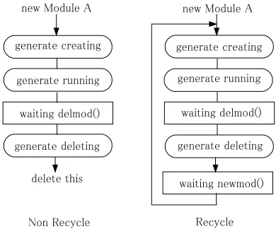
Figure 4 shows the procedure of the spawn control. If the spawn control is reused, it switches the creating,
running, deleting and user processes and deletes itself
at the end of the procedure. At the time of reusing, the
spawn control waits for the reusing and resuming of the
creating state.
(c) Limited use of user process
If the generating and/or deleting processes are un-necessary in the design, the number of calls for the
sc spawn function will be decreased. As a result, a
Figure 4. Procedure of Reusing a Process
B. Dynamic Port and Channel Pool
In a dynamic module, the ordinary ports, sc port, cannot be used for the declaration of inputs and outputs because these ports cannot be generated and eliminated after the simulation has started. In addition, the sc port has a bind method to connect with channels, but it does not have a method for disconnecting, which is unneces-sary in the design of a typical static system. The dynamic port: dc port is used for the declaration of the inputs and outputs of a dynamic module. The dynamic ports can be generated after the simulation has started, and they have a detach method for disconnection with the channels.
The proposed library has a channel pool, which is a set of static channels that generate instance of channel pool before the simulation, and manages the connection and disconnection of channels in the channel pool. The dynamic ports are implemented and managed in the same way as the channels.
The use of ports requires the description of the dec-laration for each connected channel. Using the proposed libraries, the dynamic ports dc fifo and dc signal for the
sc fifo and the sc signal are prepared respectively. In order
to connect the channels, a dynamic port which has an interface with the channels must be defined.
IV. EVALUATION OF THEPROPOSEDMETHOD
We show the experimental results of the proposed library. The Mux models, which are modeled in the ordinary description style of SystemC, are prepared as a comparison with the proposed library. In the Mux model, each module are described as static modules, and the generation and elimination of a module are described using switching of some multiplexers and de-multiplexers. The speeds are measured as the time of simulation, and the ease of modeling is measured as the length of the codes after eliminating comments, blank lines and macros for C++ with the preprocessor of gcc. The experimental environment is a Pentium4 3.2 GHz, Memory 1G byte, linux-2.6.11, gcc 3.4.3 with an optimization option “-O2” and SystemC 2.1.v1 by OSCI.
A. Hadamard Transform
The Hadamard Transform (HT) is one of the signal-processing algorithms and orthogonal conversions. Each element of the Hadamard matrix, which is used in the transform, is only +1 or -1, so HT and its inverse trans-form can be calculated by addition and subtraction (the coefficients and the power of √1
2 are omitted). Therefore,
the hardware implementation of HT is a small-scale hardware resource and high-speed processing.
The fast HT (FHT) is one of the implementations of HT and a faster algorithm, such as the Fast Fourier Trans-form algorithm for the Fourier transTrans-form. For example, an 8-point FHT(8pHT), which uses regular connections between some 2-point HTs(2pHTs), is constructed like Figure 5.
2pHT has two input and two output ports and the operations of the 2pHT are only addition and subtrac-tion for two inputs. The FHT algorithm can reduce the complexity fromO(n2)toO(nlogn)for the number n of inputs. The intersections of some 2pHT module outputs implement the sequency of primary outputs. The sequency corresponds to the frequency in the Fourier transform. FHT in Figure 5 has the outputs in the sequency order.
Figure 5. 8-point FHT
We provide a brief overview of the serial FHT (SFHT) architecture for a partial reconfiguration. In this architec-ture, the 2pHTs, Reorders and Reorders, which reorder data, are set in line, as shown in Figure 6. The SFHT architecture can construct an HT with N2 areas of circuits and a N2 delay for serial inputs and outputs. This architec-ture can change the parallelism and the number of input and output points.
When changing the number of input and output points,
Figure 6. Reconfiguration for the 8pFHT
In Figure 7, the system level description of the dy-namic module Dydy-namic HT2, which calculate as 2pTH, is shown. Input ports in0 ,in1 and output ports out0,out1 are declared as types dc fifo in and dc fifo out, respectively. As a user process, running , for example, is declared, and in the description of this process, the results of the addition and subtraction of input ports in0 and in1 are passed to the write method of out0 and out1, respectively.
Figure 7. Description of a Dynamic Module
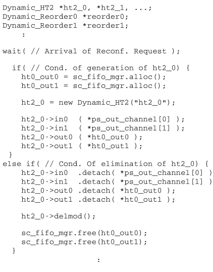
In Figure 8, the description of the control of dynamic reconfigurations is shown. This process is activated in the case of the arrival of a reconfiguration request from outside of the module. If the condition for the generation of Dynamic Module ht2 0 is satisfied, the operations of the generation of channels ht out0 and ht out1, the generation of module ht2 0, and the connection of the
channels and the ports are executed in order. If the condition for the elimination of Dynamic Module ht2 0 is satisfied, the detachment of the port from channel detach, the elimination of module delmod, and the elimination of channels free are executed in order.
In this way, the system behavior of a dynamic recon-figuration can be specified.
Figure 8. Description of the Control for a Dynamic Module
Table I shows the results for the code length. In Table I, “Data Path Modules” includes a description of the 2pHT, Reorder and Reorder’. “Management” presents a description for the control of dynamical reconfigurations. In the results for the code length, the Mux model and the model based on the proposed method have almost identical code lengths. The model based on the proposed method is slightly longer than the Mux model. The management of the model based on the proposed method is 20% or 30% longer than that for the Mux type.
Data Path Modules Management
Mux model 199 382
Proposed method 205 482
TABLE I.
CODELENGTH FORSFHT(LINE)
time, so 1,000 reconfigurations take place. Six models, which are combination of acceleration methods described in III, are also evaluated.
At first, the proposed method can simulate faster at Test 1, which has a low frequency of reconfiguration. In Test 2, the Mux model is faster than the proposed method. In the worst case, the proposed method is 16 times slower than the Mux model. In particular, in the case of model (3), the accuracy of the model and simulation is the same as that of model (1). The simulation time of model (3) can be reduced, 8% in Test 1, and 39% by model (1) in Test 2. The simulation time of model (6) is decreased: it was 20% in Test 1, and 93% in Test 2. However, the dynamic module cannot use the creating process and the deleting process for representing the reconfiguration in model (6), but the contents of description and the simulation accuracy are the same as that of the Mux type.
Test 1 Test 2 Mux model 19.1 20.4 (1)none 17.7 315.4 (2)(a) 16.9 262.8 (3)(a)+(b) 16.2 190.1 (4)(c) 15.5 130.2 (5)(a)+(c) 15.0 79.0 (6)(a)+(b)+(c) 14.1 21.9
TABLE II.
SIMULATIONTIME FORSFHT(MS)
B. Switching of the Encryption Algorithms
The hardware implementation of an algorithm can achieve high performance and low power consumption. However, there are systems that require different encryp-tion algorithms. If these algorithms are implemented in the hardware at the same time, unused algorithms waste hardware resources. Therefore, the utilization of hardware resources can be improved with DRAs, and only neces-sary algorithms are configured on the DRAs. Switchable multi-cryptographic engines have been implemented on some DRAs, such as the DRP-1.
The evaluation model implements two encryption al-gorithms, AES [15] and CAST128 [16]. The model consists of modules of AES, CAST and the management module for a dynamic reconfiguration. In the dynamic reconfiguration, the system switches AES and CAST. In this evaluation, the key length and block size are fixed as explained in the following. In AES, a 128bit key length and a 128bit block size are adopted, and in CAST, a 129bit key length and a 64bit block size are adopted. Inputs and outputs are used for 8bit serial communication.
Table III shows the results for the code lengths. In the table, “Modules” includes the line numbers of behaviors of AES and CAST for both Mux and proposed models. The numbers consist of the line number of the module interface declaration (78 and 83 in Mux and proposed method, respectively ) and common descriptions that specify the algorithms of AES and CAST (4083).
“Management” includes the line numbers of descriptions for the management of a dynamic reconfiguration. The model based on the proposed method is slightly longer than the Mux model. The proposed library has to de-fine the behaviors of the creating process and deleting processes, which are not written in the Mux model. The control part of the proposed model is also slightly longer than that of the Mux model. This is because the model based on the proposed method contains the behaviors for the connection and disconnection with channels, while the Mux model does not contain them.
Modules Management Mux model 78+4083 106 Proposed method 83+4083 100
TABLE III.
SIZE OFCODES FORENCRYPTIONS(LINE)
The simulation time is compared with the model based on the proposed method and the Mux model. Tests 1 and 2 are used for the evaluation. In the Test 1, the recon-figuration in which encryption algorithms are changed is conducted every 100 operations, and, in the Test 2, the re-configuration is conducted at every operation. The model based on the proposed method can be simulated faster in Test 1, which has a low frequency reconfiguration. In the evaluation of Test 2, the simulation speed of the Mux model is faster than that of all cases of the proposed method. The acceleration methods are confirmed with all models from (2) to (6) by the results. Models (4), (5), and (6) can reduce the simulation time from that by the Mux Model at Test 1.
Test 1 Test 2 Mux model 10.9 12.3 (1)none 11.2 88.9
(2)(a) 11.2 75.7
(3)(a)+(b) 11.2 57.6
(4)(c) 10.7 39.9
(5)(a)+(c) 10.8 29.2 (6)(a)+(b)+(c) 10.6 12.5
TABLE IV.
SIMULATIONTIME FORENCRYPTOR(MS)
V. CONCLUSION
model. Under some conditions, a higher-speed simulation was possible with the proposed library.
The design from the system level to RT level is known as an SW/HW partition, behavioral synthesis, etc. We will research the technology mapping of dynamic modules and ports to a concrete DRA.
ACKNOWLEDGMENT
This research has been supported by the Kayamori Foundation of Informational Science Advancement.
REFERENCES
[1] R. Bergamaschi and W. Lee, “Designing systems-on-chip using cores,” Proceedings of the 37th conference on Design automation, pp.430-425, 2000.
[2] Open SystemC Initiative(OSCI), http://www.sys-temc.org. [3] P. R. Panda,“SystemC - A modeling platform supporting multiple design abstractions,” International Symposium on System Synthesis(ISSS ’01), Montreal, 2001.
[4] SpecC Technology Open Consortium, http://www. specc. org.
[5] Accellera Organization, Inc., http://www.systemverilog. org.
[6] M. Gokhale and P. S. Graham:“ Reconfigurable computing: Accelerating computation with field-programmable gate arrays.” SPRINGER,2005.
[7] T.Toyo, H.Watanabe, and K.Shiba, “Implementation of Dynamically Reconfigurable Processor DAP/DNA-2,” Pro-ceedings of IEEE VLSI-TSA International Symposium on VLSI Design, Automation & TEST, pp.321-322, 2005. [8] Xilinx,“Vertex-4 Configuration Guide,” http://direct.xilinx.
com/bvdocs/userguides/j_ug071.pdf, UG071(v1.3), 2005. [9] M. Motomura: “A dynamically reconfigurable processor
architecture,” Microprocessor Forum, 2002.
[10] K. Nagami, K. Oguri, T. Shiozawa, H. Ito and R. Kon-ishi:“Plastic cell architecture: A scalable device architec-ture for general-purpose reconfigurable computing,” IEICE Transaction on Electronics, Vol.E81-C, No.9, pp.1431-1437, 1998.
[11] H. Ito, R. Konishi, H. Nakada, H. Tsuboi, Y. Okuyama and A. Nagoya, “Dynamically reconfigurable logic LSI: PCA-2,” IEICE Transaction on Information and Systems , Vol. E87-D, No. 8, pp.2011-2020, 2004
[12] A. Pelkonen, K. Masselos, and M Cup´ak, “System-Level Modeling of Dynamically Reconfigurable Hardware with SystemC,” Proceedings of International Parallels and Distributed Processing Symposium(IPDPS’03),pp.174-181,2003.
[13] A. V. de Brito, E. U. K. Melcher, and W. Rosas, “An open-source tool for simulation of partially reconfigurable systems using SystemC,” Proceedings of 2006 Emerg-ing VLSI Technologies and Architectures(ISVLSI’06), pp.434-435,2006.
[14] P. A. Hartmann, A. Schallenberg, F. Oppenhaimer, and W. Nebel, “OSSR+R:Simulation and Synthesis of Self-adaptive Systems,” Proceedings of Field Programmable Logic and Applications(FPL2006),pp.177-182, 2006. [15] J. Daemen and V. Rijmem, “AES proposal: Rijndael,”
http://csrc.nist.gov/encryption/aes/rijndael/Rijndael.pdf, 1999.
[16] A. Carlisle,“Constructing symmetric ciphers using the CAST design procedure,” Designs, Codes and Cryptog-raphy, Vol. 12, No. 3, pp. 71-104, 1997.
Kenji Asano received his M.S. degree in Computer Science and Engineering, the University of Aizu, Japan. He is currently
a CAD Engineer at NEC Electronics Corporation, Japan. His research interests include CAD for nanometer-scale LSI design, design automation for system LSI and dynamic reconfigurable architectures.
Junji Kitamichi received the B.S., M.S. and Ph.D degrees in information and computer sciences from Osaka University, Japan, in 1988, 1990 and 1999, respectively. In 1991, he joined the Department of Information and Computer Sciences at Osaka University, Japan, as a research associate. From 1999 to 2002, he was with Cybermedia Center at Osaka University, where he was a assistant professor.
In 2002, he joined School of Computer Science and Engi-neering, the University of Aizu, Japan, where he is currently an associate professor. His research interests include formal methods for VLSI design, design verification, hardware descrip-tion languages, and dynamical reconfigurable architectures. Prof. Kitamichi is a member of the IEEE Computer Society, IEICE and the IPS of Japan.
Kenichi Kuroda received his B.A. Degree in Pure and Applied Sciences in 1971, and M.Sci. Degree in Science in 1973 from Tokyo University. He received Dr. Eng. Degree in Engineering in 1991 from Tokyo University.