Resource Allocation For Device-To-Device
Communication In Millimeter Wave Underlay
Network
Job MochengoKerosi, Heywood OumaAbsaloms, Philip Kibet Langat
Abstract: High expectations are placed on the Device-to-Device (D2D) communication operating in the millimeter spectrum band to improve the capacity of future 5G network. However, D2D communication underlaying cellular network if not properly designed introduces interference in the system. Therefore, an efficient resource sharing scheme is desirable to provide a proper interference management system. In this paper, resource allocation in D2D communication in millimeter wave (mmWave) spectrum to maximize the throughput while meeting the minimum Quality of Service (QoS) requirements of the users, is investigated. A resource sharing algorithm which allocates power to a single DUE-CUE pair using the geometric programming method and then performs allocation of resource blocks (RBs) to multiple DUEs using the Hungarian Algorithm, is proposed. The efficiency of the resource allocation scheme it tested through simulation using the Close-In (CI) path loss model. The integration of mmWave technology and D2D communications is found to averagely increase the throughput of the system by 64.8 %.
Key Words: Device-to-Device, Hungarian Algorithm, Millimeter Wave, Power Allocation, Spectrum Allocation, 5G.
————————————————————
1. INTRODUCTION
THE rise of applications in need of large amount of data such as online games, video sharing and content sharing have spurred an explosion in the demand of mobile data, consequently leading to an increase of mobile traffic. These high data rate demands area challenge to the existing cellular framework. This can be attributed to scarcity of spectrum resources experienced in the current fourth generation (4G) technologies as it has attained its maximum theoretical data rates[1]. Currently, the 4G network has a latency of 15ms per 1ms sub-frame [2] compared with the required latency of between 2ms and 5ms per 1ms sub-frame for 5G. Millimeter wave (mmWave) spectrum has been proposed to be used commercially in the cellular networks to reduce congestion in the microwave spectrum[3]. The mmWave frequency band has poor propagation due to free space path loss, oxygen absorption effect, requirements of high gain directional antennas and inter-symbol interference as a result of the many reflective paths. These propagation characteristics make the mmWave spectrum better suited for short range communication of about 100m where a loss of about 20 dBm/km is negligible[4]. According to [5], this enables increased spatial reuse with beam forming techniques, highly directional antennas and interference avoidance to mitigate path loss. Device-to-Device (D2D) communication permits close proximity devices to communicate directly with less involvement of the evolved Node B (eNB)[5], [6]. Therefore, D2D communication extends the coverage of eNB through multi-hop transmission and decreases the load on the network. However, D2D communication faces some challenges in its implementation one of them being the spectrum allocation[6]. As seen in Fig.1[5], D2D communication may be classified as either inband or outband, depending on the frequency spectrum it operates in. In the outband D2D communication, the D2D users (DUs) operate in the unlicensed spectrum band[7], normally referred to as outband D2D communications. In this scenario, the cellular users (CUs) operating in the licensed spectrum band are not likely to suffer interference from DUs; also the DUs receive no interference from the CUs. However, controlling communications in the unlicensed spectrum is difficult owing to the limited rules governing communication in this band.
Fig.1 D2D communication.
1654 they get trapped in their local optimum solutions.In [14], Wang
et al. propose a resource allocation scheme which allows the DUs to reuse resource blocks of multiple CUs, but the Quality of Service (QoS) of CUs is not necessarily met. In [15] power control is investigated such that the DUs reuse resources of multiple CUs, while meeting QoS of CUs. However, they make an assumption that only one D2D pair exists in the network.The works in [16], 17, [18], investigate the problem of allocating resources to D2D communications operating in the mmWave band for the outdoor scenario. The authors propose greedy and heuristic algorithms for spectrum allocation. However, power allocation to the network users is not considered leading to throughput deterioration with the increase in number of DUs. In this paper, a resource allocation scheme for D2D communication in mmWave cellular network, to maximize throughput of the network, is formulated. At the same time, the concept of gain in system throughput as a result of the CUs sharing their resources is considered. The gain informs the decision on whether to share or not share cellular spectrum resources. The gain can either be positive or negative, indicating the benefit accrued in the network from sharing cellular resources or the negative consequence of sharing respectively. The rest of the paper is organized as follows. In Section II the system model is described and the assumptions made are given. In Section III the resource allocation problem is formulated. In Section IV a novel resource allocation scheme is proposed. In section V
simulation results are presented and discussed. The paper finally draws conclusions in Section VI.
2 SYSTEM
MODEL
2.1 Network Model
This paper considers an Underlay Inband D2D communication system, where multiple CUs and DUs co-exist and D2D communication only reuses spectrum resources assigned to the CUs due to radio resource constraints. The system model is illustrated in Fig. 2. To improve on the rate attained by DUs, the D2D pairs are permitted to reuse either the uplink or downlink resources for direct transmission. Moreover, it is assumed that in the system there are MD2D pairs and NCUEs. The D2D pairs’ index set is defined as D = *1, … , M+and CUs’ index set is defined as C = *1, … , N+. Each CU is allocated separate resource blocks (RBs) which are denoted by RB. Thus, the cth CU’s bandwidth is characterized as BW = RB × B , with B being the bandwidth of a single RB. The CUs are assumed to occupy orthogonal uplink and downlink spectrum resources, hence co-channel interference among CUs is ignored in the work. The eNB is also assumed to haveknowledge of the instantaneous channel state information (CSI) of all the links in the network.
Fig. 2. System model
2.2 Channel Model
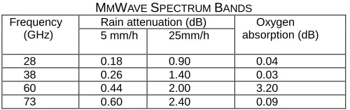
The frequency bands in the mmWave spectrum that are being explored for 5G communication and their characteristics are shown in Table 1 [19]. Results show that the bands provide ubiquitous throughput, massive antenna deployment and wireless links with better quality. However, signals in these bands are highly directive and usually suffer signal attenuation because of atmospheric absorption and obstacles as seen in Table1.
TABLE 1
MMWAVE SPECTRUM BANDS
Frequency (GHz)
Rain attenuation (dB) Oxygen absorption (dB) 5 mm/h 25mm/h
28 0.18 0.90 0.04
38 0.26 1.40 0.03
60 0.44 2.00 3.20
73 0.60 2.40 0.09
In this paper, the 28 GHz band is considered for the propagation model. The atmospheric absorption in the 28 GHz frequency band is low as compared to the 60 GHz frequency band[18]. In an environment, which is characterized by many users and a number of obstacles, a path loss model which takes care of both line of sight (LOS) and non-line of sight (NLOS) propagation is desirable[3]. The path loss is given by (1) [17].
PL = PL + PL (1)
The CI path loss model is considered for path loss modeling in this research. The model is expected to play a greater role in the 5G communication. The CI model is based on a standard free space reference distance of 1 m. It is a function of the carrier frequency and a parameter called the path loss exponent (PLE) denoted by α. The choice of d = 1 m provides mode accuracy and excellent parameter stability for outdoor Urban Micro cell channels[20]. The CI path loss at a distance d is given by (2)
PL( , d),dB- = F PL + 1 (d d* + (2)
path loss for a carrier frequency f and is given by (3).
F PL,dB- = (
* (3)
Where is the speed of light.
To take care of both NLOS and LOS cases, probability is incorporated in the path loss equation in (1). By that D2D links are expected to have more LOS signals due to their close proximity and hence the path loss in the D2D links is given by (4). The path loss for rest of the links (eNB-D2D, CU-eNB, and D2D-CU links) is given by (5) [18].
PL = PL + (1 )PL (4)
PL = PL + (1 )PL (5)
Where p1 denotes the path loss probability for LOS of the D2D links and p2 denotes the path loss probability for LOS for the non D2D links.
3.
PROBLEM
DESCRIPTION
AND
FORMULATION
3.1 Problem Description
A summary of frequently used notations in this paper is presented in Table 2. The D2D communication scenario in Fig. 2 is referred. In the uplink phase of the cellular network, the cellular user transmits to the eNB while the D2D transmitter (DTx) transmits data to the D2D receiver (DRx). During this phase the DRx receives interference from the CUE. Also, the eNB suffers interference from the DTx. If the cth cellular user shares its uplink resource blocks (RBs) with the dth D2D pair, the SINR at the eNB is given by (6).
= P
∑ , P + N
(6)
Similarly, the received SINR the dthDRx is given by (7).
= P
∑ , P + N
(7)
The optimization variables , and , are the binary indicator functions which are set to 1 if the d D2D pair reuses RBs of the CU, or to 0 if the d D2D pair does not reuse RBs of the CU, in the uplink and downlink phases respectively. No is the noise spectral density.During the downlink phase, the CUE suffers interference from the DTx, and the DRx experiences interference from the eNB. If the cth cellular usershares its downlink Resource Blocks (RBs) with the dthD2D pair. The SINR at the cthCU is then given by (8).
= P
∑ , P + N
(8)
Similarly, the received SINR at the dthDRx is given by (9).
= P
∑ , P + N
(9)
To manage interference properly, the dthDTx is allowed to reuse either the uplink RBs or the downlink RBs of cthCU at a time. Therefore the SINR at the dthDRx is expressed as (10)
= P
∑ , P
+ ∑
, P + N
(10)
The achievable channel rates, R , R and R corresponding to , and , respectively, are calculated using the Shannon’s Capacity Theorem [21].
R = BW (1 + ) R = BW (1 + ) R = BW (1 + )
(11 )
TABLE 2
SUMMARY OF NOTATIONS
Notation Description
M, N The set of Cellular Users and D2D pairs
P, P, P The transmission power of d D2D pair , CU and eNB
CU c – eNB link gain eNB – CU c link gain eNB – DU d link gain CU c – DU d link gain DTx – DRx link gain D2D pair d –CU c link gain , SINR value of CU c in the uplink
and downlink phases SINR value of the D2D pair d , , , SINR threshold values for CU c
in uplink and downlink phase
The threshold SINR value of d D2D pair
R , R The achievable rate in the uplink and downlink phase of CU c
R The achievable rate of d D2D pair
3.2 Problem Formulation
This research aims to maximize total system throughput while taking into account the minimum SINR requirements of users. To achieve this the problem is formulated as in (12).
m , (∑ R
+ ∑ R + ∑ R
+ (12)
Maximization in (13) is subject to constraints (13) – (20).
, , C (13)
, , C (14) , d D (15)
P P , C (16)
P P , d D (17)
P P , C (18)
(∑ ,
+ (∑ ,
+ = , d D, (19)
, , , * ,1+, d D, C (20)
1656 time. Constraint (20) is the binary indicator of reuse of cellular
user resources.
4 RESOURCE
ALLOCATION
SCHEME
Problem (12) is a mixed integer non-linear programing (MINLP) problem. Therefore to solve it, it is broken into a two-step problem: a power allocation problem, and a resource block assignment problem. In the first step the transmission power of each CU and DUE that maximize the throughput for both the uplink and downlink cases is obtained. In the second step, resource blocks of CUs to the D2D pairs are assigned using Hungarian algorithm with the aim of maximizing the throughput of the system.
4.1 Power Allocation
The MINLP problem given in equation (12) is converted to a geometric programming problem by fixing binary reuse indicator at 1 to yield an equation, which is in the class of convex optimization problems. The resulting problem is then solved for one resource block shared by the dthD2D pair and cthCU. Considering the uplink phase first the problem reduces to (21).
m
, (BW (1 +
P
P + N * + BW (1 + P
P + N **
(21)
Subject to constraints (22) – (25).
, , C (22)
, d D (23)
P P , C (24)
P P , d D (25)
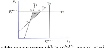
The feasible region for transmit power allocation for the DUE-CUE pair, represented by Ψ, is shown in Fig. 3-5. ∂Ψ is the boundary of Ψ. Further, Ψ is bounded by four lines T1: = ,
, T2: P = P , T3:P = P and T4: = . Also, the shape of Ψ changes with varying values of the interference and direct link gains, maximum transmission powers and SINR values
Fig. 3. Feasible region when , and
Fig. 4. Feasible region when , and
Fig. 5: Feasible region when , and
To determine the optimal power allocation (P , P ) for problem (21), the lemmas proved in [22] are applied.
Lemma 1: Either the CUE or the DUE transmits at its maximum power, that is, (P = P ) r(P = P )
Proof: According to the power and SINR constraints, region Ψ is a bounded and closed set. Further, if R(P , P ) is a continuous function, then problem (21) is a convex function.
R(P , P ) = BW (1 + P
P + N * + BW (1 + P
P + N *
(26)
Applying the logarithmic manipulation to problem (26) gives (27).
R(P , P ) = BW (( P P + N ) (
P P + N *+
(27)
Substituting(P , P ) in equation with (μP, μP ) for μ > 1, μ R and (P , P ) Ψ results in (28).
R(μP, μP )
= BW (( P P + ) (
P P + ),
(28)
With an increase in the value of 𝜇, 𝑅(𝜇𝑃, 𝜇𝑃 ) > 𝑅(𝑃 , 𝑃) contradicting the initial assumption that (𝑃, 𝑃 ) is the optimal power allocation. Thus lemma 1 is proved through contradiction. From lemma 1, the optimal transmit power resides along line BC or CD for Fig. 3, or ED for Fig. 4 or BF for Fig. 5.
Lemma 2:(P , P ) only resides at the extreme corners of Ψ.
Proof: Let: T : T ∩ ∂Ψ( = 1 t )and R(P, P )
= BW (( P P + N ) (
P P + N *+
(29)
If (P , P ) T, . And if (P , P ) T, .
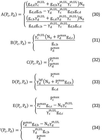
A(P , P ) =
{
( , h, + , h, h, )N , h, h, , , ( , h, + , h, h, )N
, , h, h, , ,
(30)
B(P , P ) = {
h, (N + P , ) ,
P
(31)
C(P , P) = {PP (32)
D(P , P ) = {
P (N + P , )
,
(33)
E(P, P) = {
P P
, N h, h, ,
(33)
F(P, P) = {
P , N h, h, ,
P
(34)
The feasible optimal transmit power of the DUEs in the uplink and downlink phases should be overlapped to enable the DUE to reuse the resource blocks of the CU in both uplink and downlink phases. Therefore obtaining the power allocation for downlink phase the same method is applied.
4.2 Resource Block Allocation
To this end optimal transmit power allocation, (P , P ), for a single DUE-CUE pair has been obtained. In order to ensure that there is an improvement in the network capacity as a result of sharing cellular resources, in this section the gain in throughput when the dthD2D pair reuses the resource block of the cthCU, is determined. The throughput gain, can either be positive or negative, representing the benefit accrued from the reuse of cellular resource blocks or the consequence for interference on CUs respectively. Further, the D2D pair is only permitted to access the network if it results in a positive throughput gain. Let T , represent throughput gain when dthD2D pair reuses the uplink RBs of the cth CU, and T , to represent throughput gain when dthD2D pair reuses downlink RBs of the cth CU. Then,
T , = BW (1 + P
P + N * + BW (1 + P P
+ N * BW (1 +P
N *
T , = BW (1 + P
P + N * + BW (1 + P
P + N * BW (1 +P
N *
(35)
(36)
In (35) and (36), the first term represents achievable rate of dthD2D pair, with the second term is the achievable rate of the cthCU when sharing its resource with the dthD2D pair, while the third term is the achievable rate when the cthCU is not sharing its resource. For a positive throughput gain, (35) and (36) should be greater than zero.
Since the system has multiple D2D pairs, the problem of resource block allocation is modeled as a maximum weight bipartite matching problem, which is represented in (37).
m
, , , ∑ ∑( , T
, + , T
, )
(37)
Subject to the constraints (39) and (40)
, , , * ,1+, d D, C (38)
(∑ ,
+ (∑ ,
+ = , d D (39)
This matching problem is then solved using the Hungarian Algorithm[23]. Algorithm 1 presents the pseudo code for the resource sharing scheme.
TABLE 3
RESOURCE ALLOCATION ALGORITHM
Algorithm 1: Resource Sharing algorithm
C Set of existing CUs
D Set of D2D pairs
Y Cellular reuse partners of the d DU 1. for d Ddo
2. Obtain the optimal for C do
3. Power allocation (P, P) for both uplink and downlink phases and then determine the throughput gains (T , d T , )
4. if T , (P, P) r T , (P, P) then 5. Y;
6. end if 7. end for 8. end for
9. Obtain the reuse pattern for multiple DUEs by feeding the throughput gain matrix to the Hungarian Algorithm.
5 SIMULATION
RESULTS
AND
DISCUSSION
In this section the simulation results obtained are presented in to validate the proposed power and spectrum allocation scheme for the mmWave underlay network. In the simulation M potential DU pairs and NCUEs are distributed randomly in the coverage area of the eNB with a radius R. The cluster radius, r, is defined as the distance between transmitter and receiver of a D2D pair. Simulation parameters are set as in Table 4[16], [17], [18], [24] unless specified otherwise.
TABLE 4
SIMULATION SYSTEM PARAMETERS
Parameter Value
Cell radius (R) 500 m
Radius of DUEs (r) 10 m
Total system bandwidth (BW) 1 GHz
Carrier Frequency (fc) 28 GHz
Bandwidth per RB (BRB) 180 kHz
Maximum transmit power of DUE or CUE
(P , P ) 25 dBm
1658 SINR threshold for CUE or DUE
( , , , r ) 0 dB
D2D links path loss probability , ( ) 0.2 Non-D2D links path loss probability,( ) 0.8 Path loss exponent α; (LOS, NLOS) 2, 2.92 Shadowing coefficient σ ; (LOS, NLOS) 5.8 dB, 8.7 dB Noise Spectral density (N0) -174 dBm/Hz
Four metrics are used to evaluate the performance of the proposed scheme: TheD2D throughput,R , Cellular throughput,R , system throughput, R , and the success rate.
These are given in (40) – (42).
R = ∑ R
R = ∑ R +
∑ R
R = R + R
(40)
(41)
(42)
The success rate is the ratio of the D2D pairs that find a cellular reuse partner to the total number of D2D pairs in need of resources for communication. The proposed scheme is compared with an algorithm in [25], which permits D2D pairs to only reuse uplink (ORU) RBs. In [25], a resource allocation scheme which maximizes the throughput gain is proposed and solved in two steps. It first calculates the throughput gain for a single D2D-CU pair and then uses the maximum weight bipartite matching to assign RBs to multiple D2D pairs.
5.1 Varying DUE density
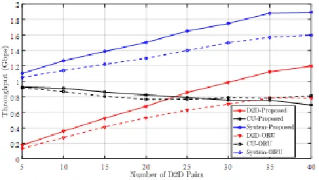
In the first simulation, the number of CUs was maintained at N = , while the number of DUs was varied. Other parameters were as per Tables 4. The results of Fig. 6 and Fig. 7 were obtained.
Fig. 6.Variationof throughput with number of D2D pairs
The D2D throughput and system throughput increase as the number of D2D pairs increases from 5 to 40, and performance of proposed scheme outperforms the ORU algorithm. It is also observed that the CUs decreases by1 %inferring that the system can allow D2D communication as underlay while still meeting the QoS requirements of CUs. As the number of D2D pairs increase, the system throughput increases, indicating the significance of allowing D2D communication in the cellular network.
Fig. 7: Variation of success rate of D2D pairs with number of D2D pairs
Since, the number of CUs is constant in this simulations set, the success rate reduces as the number of D2D pairs increase. The success rate of the proposed scheme is better as compared of the ORU scheme, for instance when M = 35 the success rate for the proposed scheme is 1 while that of ORU scheme is 0.59. This is because in the proposed scheme the D2D pairs are allowed to reuse both uplink and downlink RBs while the ORU scheme only permits the D2D pairs to reuse the uplink RBs of CUs.
5.2 Varying D2D cluster radius
In the second simulation, the D2D cluster radius was varied while the number of CUs was maintained at N = and the D2D pairs at M = . The other parameters were as per Table 4. The results of Fig. 8 and Fig. 9 were obtained.
Fig. 8. Variation of system throughput with D2D cluster radius
As the D2D cluster radius increases from 10 m to 60 m, the system throughput, D2D throughput and success rate decreases for both the proposed and the benchmark scheme. The increase in the D2D cluster radius results in an increase in the D2D transmit power and a consequent increase in the interference level, hence a decrease in D2D throughput and success rate. As the D2D cluster radius increases from 10 m to 60 m, the D2D throughput of the proposed scheme decreases by 38.9%, while that of ORU decreases by 31.6 %. The cellular throughput remains relatively constant as its minimum SINR requirements are satisfied, hence a decrease in the system throughput by .7% and 16.3% for the proposed and ORU scheme respectively.
5.3 Varying CU cell radius
In this simulation, the cell radius was varied while maintaining N = and M = , and the other parameters as per Tables 3 and 4. The results of Fig. 10 and Fig. 11 were obtained.
Fig. 10. Variation of system throughput with CU cell radius
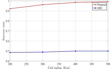
Fig. 11.Variation of D2D success rate with CU cell radius
The D2D throughput and success rate increases with an increase in the cell radius from 200 m to 500 m. With an increase in the cell radius, the distance between D2D pairs and CUs and the distance to the eNB increases. Hence, in the uplink phase the interference at the D2D receiver from the CUs and interference from D2D transmitter to the eNB is reduced, also in the downlink phase the interference at the D2D receivers from the eNB and the interference from D2D transmitters to the CUs is reduced. However, as the cell radius increases from 200 m to 500 m, the CU throughput decreases by 6.33 %, due to reduced link gain between the eNB and the CUs. Since in this simulation case the number D2D pairs exceeds that of CUs, the D2D throughput is dominant, hence an increase in the system throughput by 1 .9% as the cell radius increases.
5.4 Varying SINR thresholds
In this simulation, the SINR thresholds( , = , = = h)were varied while maintaining N = and M = , and the
other parameters as per Tables 4. The results of Fig. 12 and Fig. 13 were obtained.
Fig. 12.Variation of system throughput with SINR threshold
Fig. 13. Variation of D2D success rate with SINR threshold
From the plots it is seen that the system throughput and the D2D throughput decreases by .1 % and 19. % respectively, as the SINR threshold increases from 0 to 20 dB. The success rate also decrease from 0.99 to 0.97. This is because an increase in the SINR threshold lowers chances of a D2D user obtaining a cellular reuse partner. In both cases the proposed scheme performs better compared to the ORU scheme. However the CUs throughput relatively increases by . % as the SINR threshold increases since the chances of D2D pairs reusing the cellular resources is reduced.
6
CONCLUSION
1660 network. The throughput of the CUs averagely decreases by
1 %thus guaranteeing the QoS for both the DUs and CUs.
ACKNOWLEDGMENT
This work was supported by the Pan African University Institute of Science, Technology and Innovations(PAUSTI).
REFERENCES
[1] Cisco, ―Cisco Visual Networking Index : Global Mobile Data Traffic Forecast Update , 2013 – 2018,‖ 2015. [2] Y. Zhang, F. Li, M. Al-qaness, and X. Luan, ―A
Resource Allocation Scheme for Multi-D2D Communications Underlaying Cellular Networks with Multi-Subcarrier Reusing,‖ Applied Sciences, vol. 7, no. 2, Multidisciplinary Digital Publishing Institute, pp. 1–16, 2017.
[3] T. S. Rappaport, R. W. Heath, R. C. Daniels, and J. N. Murdock, Millimeter wave wireless communications. Pearson Education, 2015.
[4] K. C. Huang and Z. Wang, Millimeter Wave Communication Systems, vol. 29. John Wiley & Sons-IEEE Press, 2011.
[5] O. Bello and S. Zeadally, ―Intelligent device-to-device communication in the Internet of Things,‖ IEEE Systems Journal, vol. 10, no. 3, pp. 1172–1182, 2016. [6] M. Tehrani, M. Uysal, and H. Yanikomeroglu,
―Device-to-device communication in 5G cellular networks: Challenges, solutions, and future directions,‖ IEEE Communications Magazine, vol. 52, no. 5, pp. 86–92, 2014.
[7] R. Liu, G. Yu, F. Qu, and Z. Zhang, ―Device-to-device communications in unlicensed spectrum: Mode selection and resource allocation,‖ IEEE Access, vol. 4, pp. 4720–4729, 2016.
[8] X. Lin, J. G. Andrews, and A. Ghosh, ―Spectrum sharing for deviceto-device communication in cellular networks,‖ IEEE Transactions on Wireless Communications, vol. 13, no. 12, pp. 6727–6740, 2014.
[9] G. Yu, L. Xu, D. Feng, R. Yin, G. Y. Li, and Y. Jiang, ―Joint mode selection and resource allocation for device-to-device communications,‖ IEEE Transactions on Communications, vol. 62, no. 11, pp. 3814–3824, 2014.
[10] C.-H. Yu, K. Doppler, C. B. Ribeiro, and O. Tirkkonen, ―Resource sharing optimization for device-to-device communication underlaying cellular networks,‖ IEEE Transactions on Communications, vol. 10, no. 8, pp. 2752–2763, 2011.
[11] L. Ferdouse, W. Ejaz, K. Raahemifar, A. Anpalagan, and M. Markandaier, ―Interference and throughput aware resource allocation for multi-class D2D in 5G networks,‖ IET Communications, vol. 11, no. 8, pp. 1241–1250, 2017.
[12] G. H. Sim, A. Loch, A. Asadi, V. Mancuso, and J. Widmer, ―5G Millimeter-Wave and D2D Symbiosis: 60 GHz for Proximity-Based Services,‖ IEEE Wireless Communications, vol. 24, no. 4, pp. 140–145, 2017. [13] M. Zulhasnine, C. Huang, and A. Srinivasan, ―Efficient
resource allocation for device-to-device communication underlaying LTE network,‖ IEEE 6th International Conference on Wireless Mobile Computation, Caen, France, pp. 368–375, Jun-2010.
[14] B. Wang, L. Chen, X. Chen, X. Zhang, and D. Yang, ―Resource allocation optimization for device-to-device communication underlaying cellular networks. ,‖ In Proceedings of the IEEE Vehicular Technology Conference (VTC Spring), Budapest, Hungary, pp. 1– 6, May-2011.
[15] J. Wang, D. Zhu, C. Zhao, J. C. F. Li, and M. Lei, ―Resource sharing of underlaying device-to-device and uplink cellular communications,‖ IEEE Communications Letters, vol. 17, no. 6, pp. 1148– 1151, 2013.
[16] G. D. Swetha and G. R. Murthy, ―D2D communication as an underlay to next generation cellular systems with resource management and interference avoidance,‖ Proceedings of the 2017 International Conference on Wireless Communications, Signal Processing and Networking, WiSPNET 2017, Chennai,India, India, pp. 1348–1352, Jan-2017.
[17] Z. Guizani and N. Hamdi, ―MmWave E-band D2D communications for 5G-underlay networks: Effect of power allocation on D2D and cellular users throughputs,‖ Proceedings - IEEE Symposium on Computers and Communications, IEEE, Messina, Italy, pp. 114–118, Aug-2016.
[18] Z. Guizani and N. Hamdi, ―Spectrum resource management and interference mitigation for D2D communications with awareness of BER constraint in mmWave 5G underlay network,‖ Proceedings - IEEE Symposium on Computers and Communications, Messina, Italy, pp. 855–860, Aug-2016.
[19] Y. Niu, Y. Li, D. Jin, L. Su, and A. V Vasilakos, ―A Survey of Millimeter Wave Communications for 5G : Opportunities and Challenges,‖ Journal of Mobile Communication, Computation and Information, vol. 21, no. 8, pp. 1–17, Feb. 2015.
[20] T. S. Rappaport, G. R. MacCartney, M. K. Samimi, and S. Sun, ―Wideband millimeter-wave propagation measurements and channel models for future wireless communication system design,‖ IEEE Transactions on Communications, vol. 63, no. 9, pp. 3029–3056, 2015. [21] A. Asadi, Q. Wang, and V. Mancuso, ―A survey on
device-to-device communication in cellular networks,‖ IEEE Communications Surveys and Tutorials, vol. 16, no. 4, pp. 1801–1819, 2014.
[22] Y. Chen, X. Yuan, M. E. Mkiramweni, and X. Wu, ―Joint resource allocation and power control for cellular and device-to-device multicast based on cognitive radio,‖ IET Communications, vol. 8, no. 16, pp. 2805–2813, 2014.
[23] H. W. Kuhn, ―The Hungarian method for the assignment problem,‖ Naval Research Logistics (NRL), vol. 52, no. 1, pp. 7–21, 2005.
[24] X. Cai, J. Zheng, Y. Zhang, and H. Murata, ―A Capacity Oriented Resource Allocation algorithm for device-to-device communication in mobile cellular networks,‖ 2014 IEEE International Conference on Communications, Sydney, Australia, pp. 2233–2238, Jun-2014.