STUDY OF MODELLING & DEVELOPMENT OF
ANTILOCK BRAKING SYSTEM
VikasFadat
1, AvinashDhage
2, AkshayGaikwad
31,2,3
B.E. Scholar BVCOE&RI Nashik(India)
ABSTARCT
Antiknock braking systems are used in modern cars to prevent the wheels from locking after brakes are applied.
The dynamics of the controller needed for antiknock braking system depends on various factors. The vehicle
model often is in nonlinear form. Controller demand to provide a controlled torque necessary to maintain
optimum value of the wheel slip ratio.The slip ratio is represented in terms of vehicle velocity and wheel
rotation.In present work first of all system dynamic equations are explained and a slip ratio is expressed in
terms of system variables namely vehicle linear velocity and angular speed of the wheel. By exempt a bias
braking force system, response is obtained using Simulation models. Using the linear control strategies like P -
type, PD - type, PI - type, POD - type the effectiveness of maintaining desired slip ratio is tested. It is always
looked that a steady state error of 10% occurring in all the control system models.
I. INTRODUCTION
Anti-lock brake systems (ABS) prevent brakes from locking during braking. Under normal braking conditions
the driver controls the brakes. However, during severe braking or on slippery roadways, when the driver causes
the wheels to approach lockup, the antilock system takes over. ABS modulates the brake line pressure
independent of the pedal force, to bring the wheel speed back to the slip level range that is necessary for optimal
braking performance. An antilock system consists of wheel speed sensors, a hydraulic modulator, and an
electronic control unit. The ABS has a feedback control system that modulates the brake pressure in response to
wheel deceleration and wheel angular velocity to prevent the controlled wheel from locking. The system shuts
down when the vehicle speed is below a pre-set threshold.
1.1
Importance Of Antilock Braking Systems
The objectives of antilock systems are threefold:
1. to reduce stopping distances,
2. to improve stability, and
3. to improve steerability during braking.
These are explained below
Stopping Distance
The distance to stop is a function of the mass of the vehicle, the initial velocity, and the braking force. By
maximizing the braking force the stopping distance will be minimized if all other factors remain constant.
However, on all types of surfaces, to a greater or lesser extent, there exists a peak in fiction coefficient. It
fictional force and, therefore, minimum stopping distance. This objective of antilock systems however, is
tempered by the need for vehicle stability and steerability.
Stability
Although decelerating and stopping vehicles constitutes a fundamental purpose of braking systems, maximum
friction force may not be desirable in all cases, for example not if the vehicle is on a so-called p-split surface
(asphalt and ice, for example), such that significantly more braking force is obtainable on one side of the vehicle
than on the other side. Applying maximum braking force on both sides will result in a yaw moment that will
tend to pull the vehicle to the high friction side and contribute to vehicle instability, and forces the operator to
make excessive steering corrections to counteract the yaw moment. If an antilock system can maintain the slip
of both rear wheels at the level where the lower of the two friction coefficients peaks, then lateral force is
reasonably high, though not maximized. This contributes to stability and is an objective of antilock systems.
Steerability
Good peak frictional force control is necessary in order to achieve satisfactory lateral forces and, therefore,
satisfactory steerability. Steerability while braking is important not only for minor course corrections but also
for the possibility of steering around an obstacle. Tire characteristics play an important role in the braking and
steering response of a vehicle. For ABS-equipped vehicles the tire performance is of critical significance. All
braking and steering forces must be generated within the small tire contact patch between the vehicle and the
road. Tire traction forces as well as side forces can only be produced when a difference exists between the speed
of the tire circumference and the speed of the vehicle relative to the road surface. This difference is denoted as
slip. It is common to relate the tire braking force to the tire braking slip. After the peak value has been reached,
increased tire slip causes reduction of tire-road friction coefficient. ABS has to limit the slip to values below the
peakvalue to prevent wheel from locking. Tires with a high peak friction point achieve maximum friction at 10
to 20% slip. The optimum slip value decreases as tire-road friction decreases.
The ABS system consists of the following major subsystems.
Wheel-Speed Sensors
Electro-magnetic or Hall-effect pulse pickups with toothed wheels mounted directly on the rotating components
of the drivetrain or wheel hubs. As the wheel turns the toothed wheel (pulse ring) generates an AC voltage at the
wheel-speed sensor. The voltage frequency is directly proportional to the wheel's rotational speed.
Electronic Control Unit (ECU)
The electronic control unit receives, amplifies and filters the sensor signals for calculating the wheel rotational
speed and acceleration. This unit also uses the speeds of two diagonally opposed wheels to calculate an estimate
for the speed of the vehicle. The slip at each wheel is derived by comparing this reference speed with the speeds
of the individual wheels. The "wheel acceleration" and "wheel slip" signals serve to alert the ECU to any
locking tendency. The microcomputers respond to such an alert by sending a signal to trigger the pressure
control valve solenoids of the pressure modulator to modulate the brake pressure in the individual wheel-brake
cylinders. The ECU also incorporates a number of features for error recognition for the entire ABS system
(wheel-speed sensors, the ECU itself, pressure-control valves, wiring harness). The ECU reacts to a recognized
defect or error by switching off the malfunctioning part of the system or shutting down the entire ABS.
The hydraulic pressure modulator is an electro-hydraulic device for reducing, holding, and restoring the pressure
of the wheel brakes by manipulating the solenoid valves in the hydraulic brake system. It forms the hydraulic
link between the brake master cylinder and the wheel-brake cylinders. The hydraulic modulator is mounted in
the engine compartment to minimize the length of the lines to the brake master cylinder and the wheel-brake
cylinders. Depending on the design, this device may include a pump, motor assembly, accumulator and
reservoir.
1.2 Literature Review
Following literature is surveyed relating to ABS.
Mirzaeinejad and Mirzaei [1] have applied a predictive approach to design a non- linear model-based controller
for the wheel slip. The integral feedback technique is also employed to increase the robustness of the designed
controller. Therefore, the control law is developed by minimizing the difference between the predicted and
desired responses of the wheel slip and it’s integral. Baslamisliet al. [2] proposed a static-state feedback control
algorithm for ABS control. The robustness of the controller against model uncertainties such as tire longitudinal
force and road adhesion coefficient has been guaranteed through the satisfaction of a set of linear matrix
inequalities. Robustness of the controller against actuator time delays along with a method for tuning controller
gains has been addressed. Further tuning strategies have been given through a general robustness analysis,
where especially the design conflict imposed by noise rejection and actuator time delay has been addressed.
Choi [3] has developed a new continuous wheel slip ABS algorithm. here ABS algorithm, rule-based control of
wheel velocity is reduced to the minimum. Rear wheels cycles independently through pressure apply, hold, and
dump modes, but the cycling is done by continuous feedback control. While cycling rear wheel speeds, the
wheel peak slips that maximize tire-to-road friction are estimated. From the estimated peak slips, reference
velocities of front wheels are calculated. The front wheels are controlled continuously to track the reference
velocities. By the continuous tracking control of front wheels without cycling, braking performance is
maximized.Rangelov [4] described the model of a quarter-vehicle and an ABS in MATLAB-SIMULINK. In
this report, to model the tire characteristics and the dynamic behavior on a flat as well as an uneven road, the
SWIFT-tire model is employed. Sharkawy [5] studied the performance of ABS with variation of weight, friction
coefficient of road, road inclination etc. A self-tuning PID control scheme to overcome these effects via fuzzy
GA is developed; with a control objective to minimize stopping distance while keeping slip ratio of the tires
within the desired range. Poursmad [6] has proposed an adaptive NN- based controller for ABS. The proposed
controller is designed to tackle the drawbacks of feedback linearization controller for ABS. Topalovet al. [7]
proposed a neurofuzzy adaptive control approach for nonlinear system with model uncertainties, in antilock
braking systems. The control scheme consists of PD controller and an inverse reference model of the response
of controlled system. Its output is used as an error signal by an online algorithm to update the parameters of a
neuro-fuzzy feedback controller. Patil and Longoria[8] have used decoupling feature in frictional disk brake
mechanism derived through kinematic analysis of ABS to specify reference braking torque is presented.
Modelling of ABS actuator and control design are described. Layne et al. [9] have illustrated the fuzzy model
reference learning control (FMRLC). Braking effectiveness when there are transition between icy and wet road
hence the brake pressure. The performance of controller and hydraulic modulator are assessed by the hardware
in loop (HIL) experiments. Onitet al. [11] have proposed a novel strategy for the design of sliding mode
controller (SMC). As velocity of the vehicle changes, the optimum value of the wheel slip will also alter. Gray
predictor is employed to anticipate the future output of the system.
1.3 Scope & Objective Of Present Work
During the design of ABS, nonlinear vehicle dynamics and unknown environment characters as well as
parameters, change due to mechanical wear have to be considered. PID controller are very easy to understand
and easy to implement. However PID loop require continuous monitoring and adjustments. In this line there is a
scope to understand improved PID controllers with mathematical models.
The present work, it is planned to understand and obtain the dynamic solution of quarter car vehicle model to
obtain the time varying vehicle velocity and wheel. After identification of system dynamics a slip factor defined
at each instance of time will be modified to desired value by means of a control scheme. Various feedback
control schemes can be used for this purpose. Simulation are carried out to achieve a desired slip factor with
different control scheme such as
1) Proportional Feedback control
2) Proportional Derivative Feedback Control
3) Proportional Integral Feedback Control
4) Proportional Integral Derivative Feedback Control
Graphs of linear velocity, stopping distance and slip ratio for each system is plotted and compared with each
other. At the end, possible alternate solutions are discussed.
The work is inspired from the demo model of ABS provided in Simulink software.
1.4 Organisation Of Thesis
Chapter 2 describes the mathematical modelling of quarter vehicle and vehicle dynamic equations used to
describe the system. Feedback control systems which are used for ABS are explained. Simulink Models of each
control system are described. Chapter 3 contains various graphs obtained from each of Simulink models.
Comparison and discussion between different control schemes are shown. Chapter 4 concludes the above work.
It contains summary of work and throws light on future scope for further studies and development.
II. MATHEMATICAL MODELLING
2.1 Vehicle Dynamics
Basically, a complete vehicle model that includes all relevant characteristics of the vehicle is too complicated
for use in the control system design. Therefore, for simplification a model capturing the essential features of the
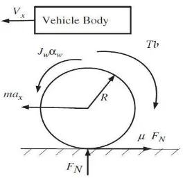
vehicle system has to be employed for the controller design. The design considered here belongs to a quarter
Fig 2.1 Quarter Vehicle Model
III. CONCLUSION
In this thesis an attempt is made to grasp the application of various type of linear controller used for anti-lock
braking systems. The system was modeled with a one fourth vehicle dynamics and differential equation of
motion was formulated. The slip ratio is used contain as a criterion for this control work. Friction force and
normal reaction are intention of slip ratio and in turn entire equations were nonlinear. The second order
differential equations were written as three state space equations (1st order equations) and solutions are obtained
by time integration method and are directly achieved with MAZATLAN Simulation block diagrams. The time
histories of the wheel, stopping distance of the vehicle, and slip factor divergences are obtained for benchmark
problem available in literature. Various central strategies like P-type, PD-type, PI-type, and PID-type have been
implemented to augment the constant braking torque so as to control the slip ratio.
REFERENCE
[1] H. Mirzaeinejad, M. Mirzaei, ‘A novel method for non-linear control of wheel slip in anti-lock braking systems’, Control Engineering Practice vol. 18, pp. 918–926, 2010
[2] S. Ç.baslamisli, I. E. Köse and G Anlas, ‘Robust control of anti-lock brake system’, Vehicle System
Dynamics, vol. 45, no. 3, pp. 217-232, March 2007
[3] S. B. Choi, ‘Antilock Brake System with a Continuous Wheel Slip Control to Maximize the Braking
Performance and the Ride Quality’, IEEE Transactions on Control Systems Technology, vol. 16, no. 5,
September 2008
[4] K.Z. Rangelov, SIMULINK model of a quartervehicle with an antilock braking system, Master’s Thesis
[5] AckermansInstituut, 2004102
[6] A. B. Sharkawy,‘Genetic fuzzy self-tuning PID controllers for antilock braking systems’ Engineering
Applications of Artificial Intelligence, vol. 23, pp. 1041–1052, 2010
[7] A. Poursamad,‘Adaptive feedback linearization control of antilock bracking system using neural networks’,
Mechatronics, vol. 19, pp. 767-773, 2009
[8] A. V. Talpov, E. Kayancan, Y. Onit and O. Kaynak, ‘Nero-fussy control of ABS using variable
structure-system-based algorithm’, Int. Conf. On Adaptive & Intelligent System, IEEE Comput Society, DOI
10.1.1109 / ICAIS.2009.35/ pp.166
[9] C. B. Patil and R. G. Longoria, ‘Modular design and testing of antilock brake actuation and control using a scaled vehicle system’, Int. J. of vehicle system modelling and testing, vol.2, pp. 411-427, 2007
[10] J. R. Layne, K. M. Pessino, S. Yurkarith, ‘Fuzzy learning control for antiskid braking system’, IEEE Trans.