GENERATION OF TRANSIENT
VOLTAGES DUE TO DIRECT
LIGHTNING ON GROUNDING GRIDS
K.V.SATYANARAYANA
Research Scholar, Dept. of Electronics and Communication Engineering,
A.U. College of Engineering (A), Andhra University, Visakhapatnam, Andhra Pradesh, India. Email: [email protected]
Prof. G.S.N.RAJU
Vice-chancellor,
Andhra University, Visakhapatnam, Andhra Pradesh, India Email: [email protected]
Abstract:
The analysis of EMC problems caused by transient current and voltage on grounding grids created by lightning surges is carried out in the present work. Although this problem is considered by Zago.F et al. [26] complete data on the variation of transient voltages as a function of time under different resistivity conditions is not available. Considering the TLM concept has reported by Zago.F computations are made to obtain the data on transient voltage variations. As the results presented in this work are very useful in solving lightning related EMC problems.
Keywords: Grounding grids, Lightning, TLM, Transient Voltages, EMC. 1. INTRODUCTION
The lightning performance of a grounding system has an important role in power system reliable operation. Lightning is the most important external transient phenomenon that causes transmission-line defects, equipment damages, terrible induced high voltages as well as electromagnetic compatibility EMC [6] Problems.
When lightning strikes an electric substation, large currents produced by the stroke flow in the grounding system and dissipate in the soil. The electromagnetic fields generated by such high currents may cause damage to equipment and are dangerous to people working close by. Grounding grids are considered an effective solution for grounding system for all sites which must be protected from lightning strokes such as microwave towers, petroleum fields, electric substations, plants and buildings.
Grounding grids produce equipotential surfaces. Earthing systems are used to divert high currents to the earth. When high impulse currents excite a grounding system, the transient electromagnetic fields are generated in the soil around the conductors. The electric-field strength in the soil rises with the increment of the impulse current amplitude. When the electric-field strength surrounding the conductor exceeds its critical value, soil breakdown [11],[15],[18] around the conductor will occur. It will make the potential drop around the grounding conductor smaller. It also converts the affected portion of the soil from an insulator to a conductor due to the soil resistivity of the earth [13].
The importance of good grounding system should satisfy the following criteria: (1) Protect from risks on electrical and electronic devices.
(2) Reduce the cost.
(3) Reduce the risks for human by decreasing the touch and step voltages [20] which are the most
important parameters for grounding system . (4) Make simple return path for the return surge current that developed from lightning.
In order to overcome the above criteria, the following measures are useful:
(1) The spacing between grounding wires should be arranged in such a way that the step and touch
voltages will be smaller than the safe value for the personal. (2) The earthen conductor should be connected to grounding system at such points in order to reduce
the ground potential rise. (3) For different soil structures, the grounding system should be kept in such a way that it can take
(4) The size of the grounding system should be big enough to decrease the maximum potential rise
when surge current enter it. The analysis of earthing system is carried out with the following.
* Transmission Line Theory [5], [7], [22] * The Electromagnetic Field Theory [3], [4], [24] * Circuit Theory [1], [2], [17], [21]
The circuit theory approach is in time domain and it takes into account the mutual coupling effects between the grounding wires. In this method, an earth conductor is replaced by an equivalent π-circuit consisting of R-L-C elements.
The Transmission line approach [19] can be either in time domain or in frequency domain and the interconnected linear ground conductor is treated by the travelling wave technique, but this model neglects the mutual electromagnetic coupling between the parts of the grounding structure. The electromagnetic field theory is considered to be accurate and flexible because it applies the Maxwell’s Equations with minimum possible approximations. The problems are defined in terms of retarded potentials and are solved by the method of moments. The radiation effects are taken into account.
The above models have advantages and disadvantages, even though the TLM could be considered more effective. This model is based on finite element analysis [12], [14]. The transmission line approach is used for modelling transient behaviour of grounding systems for engineering application. The conventional transmission line approach with parameters (L, C, and R) will be extended from a single grounding wire to grounding grids. The grounding systems are structured with good conductors. Every conductor is assumed to be a lossy transmission line. It is also assumed that the radius of the conductors is much smaller than the buried depth and the length of the wire. The conductor is characterised by its electrical properties and dimensions. Grounding resistance slightly decreases, when the grounding electrode is vertically buried from the value obtained when it is buried horizontally. Further, the computational time required for Transmission Line approach is extremely less compared to the Electromagnetic Field approach.
The soil is modelled as a linear and uniform half space characterized by conductivity, relative permittivity and permeability, thus making the soil a lossy medium. The current is partially flowing along the conductors, and partly dissipating from its surface into the soil in a radial direction. In this the ionization of the soil is not considered [18].
It has been found from analytical method that the voltage induced and impedance [16] is high when the current injection point is at the corner of the grid. If the current injection is incident at any other location of the grid, the grid exhibits lower values of both. It is also found that the soil resistivity with 20,000 Ωm
exhibits the highest transient voltage than small values of resistivity due to lower value of conductivity. 2. FORMULATION
To use TLM in simulations of grounding grids, it is necessary to consider all conductors, which make up the earthing system.
The parameters of the grounding grid are computed from the following equations [8].
G = ρπ ln√ 1 S/m] (1)
L μπ ln√ 1 H/m] (2)
R = σπ [Ω/m] (3)
C = πε ln√ 1 F/m] (4)
Here,
L is the inductance, G is the conductance, C is the capacitance, R is the resistance, a is the conductor radius ,
d is the conductor depth in the soil,
r is the permittivity, µr is the permeability.
The grounding grid is used to simulate with parameters 36 and µr = 1 for different values of soil resistivities.
The double exponential current applied is given by [9],[10],[23].
i(t) = I0( e-αt – e-βt ) (5) Here,
I 0 = 1.02 kA, = 0.1x10⁶s-1, β = 2.03x10⁶s-1. 3. RESULTS
For simulation, the phenomenon of soil ionization is not taken into account and the parameters are assumed to be independent of frequency. The depth and geometric dimensions of the grounding grid are shown in fig. (1). Copper with diameter equal to 0.015m is used for all conductors.
Fig.1 Grounding grid
The transient voltages at points A(centre) and B(corner) of the grounding grid is shown in the fig. (2). It is found that the highest transient voltage is at the corner than at centre.
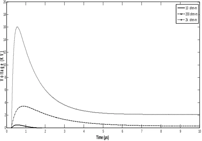
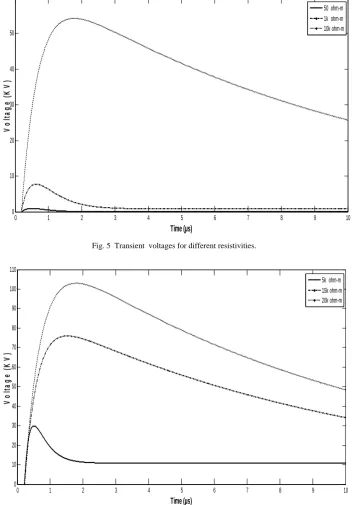
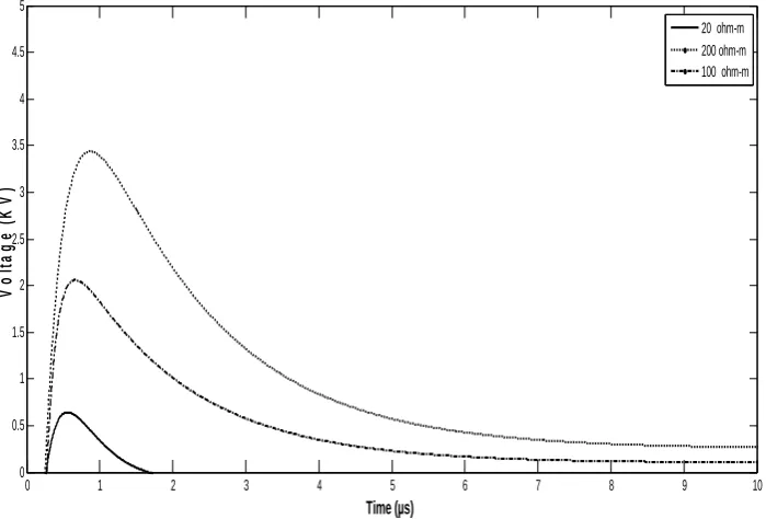
The transient voltages for different values of soil resistivity are illustrated in figs. ( 3 – 8 ). It has been found that the voltage induced is high when the soil resistivity is high.
Fig.2 Transient voltages at points A and B of the grounding grid.
0 5 10 15 20 25 30
-0.2 -0.1 0 0.1 0.2 0.3 0.4 0.5 0.6
Time (µs)
V
o
lt
ag
e (
K
V
)
Fig. 3 Transient voltages for different resistivities.
Fig. 4 Transient voltages for different resistivities.
0 1 2 3 4 5 6 7 8 9 10
0 2 4 6 8 10 12 14 16 18 20
Time (µs)
V
o
lt
ag
e (
K
V
)
10 ohm-m 200 ohm-m 2k ohm-m
0 1 2 3 4 5 6 7 8
0 1 2 3 4 5 6 7 8
Time ( µs)
V
o
lt
ag
e (
K
V
)
Fig. 5 Transient voltages for different resistivities.
Fig. 6 Transient voltages for different resistivities.
0 1 2 3 4 5 6 7 8 9 10
0 10 20 30 40 50 60
Time (µs)
Vo
lt
a
g
e
(
K
V)
50 ohm-m 1k ohm-m 10k ohm-m
0 1 2 3 4 5 6 7 8 9 10
0 10 20 30 40 50 60 70 80 90 100 110
Time (µs)
Vo
lt
a
g
e
(
K
V
)
Fig. 7 Transient voltages for different resistivities.
Fig. 8 Transient voltages for different resistivities.
4. CONCLUSIONS
Paper presents analysis of the influence of different values of soil resistivity on the transient performance of Grounding Grids subjected to lightning current impulse. Small spaces between conductors reduce the maximum Ground Potential Rise (GPR) only in case when meshes are significantly smaller than effective area. Depth of grounding grid is very small influence (Smaller depth slightly reduces voltage). Influence of soil resitivity (in poorly and dry conductive soil has maximum transient voltages are much higher than in wet and more conductive soil). A grounding grid presented to transient voltages caused by lightning surges using the numeric method TLM [7] is studied. The transient voltages for different values of soil resistivity have been calculated.
0 1 2 3 4 5 6 7 8 9 10
0 0.5 1 1.5 2 2.5 3 3.5 4 4.5 5
Time (µs)
Vo
lt
a
g
e
(
K
V
)
20 ohm-m 200 ohm-m 100 ohm-m
0 1 2 3 4 5 6 7 8 9 10
0 0.5 1 1.5 2 2.5 3 3.5 4 4.5 5
Time (µs)
V
o
lt
ag
e (
K
V
)
References
[1] A. Geri, “Practical Design Criteria of Grounding Systems under Surge Conditions”, 25th International Conferencenc Lightning
Protection, 18-22 September 2000, pp 458-463.
[2] M. Ramamoorty, M. M. Babu Narayanan, S. Parameswaran, D.Mukhedkar, “Transient Performance of Grounding Grids”, IEEE
Transactions on Power Delivery”, Vol. 4, pp 2053-2059, October 1989.
[3] Leonid D. Grcev, “Computer Analysis of Transient Voltages in Large Grounding Systems”, IEEE Transactions on Power Delivery,
Vol. 11, No. 2, April 1996, pp 815-823.
[4] W. Xiong, F. P. Dawalibi, “Transient Performance of Substation Grounding Systems Subjected to Lightning and Similar Surge
Currents”, IEEE Transactions on Power Delivery, Vol. 9, No. 3, July 1994, pp, 1412-1420.
[5] A. D. Papalexopoulos and A. P. Meliopoulos, “Frequency dependent Characteristics of Grounding Systems”, IEEE Transactions on
Power Delivery, Vol. PWRD-2, pp 1076-1081 October 1987.
[6] Johns P. B. and Beurle R. L.,”Numerical Solution of 2-dimensional Scattering Problems Using a Transmission-line Matrix”, Proc.
IEE, 1971,118, pp 1203-1208.
[7] Christopoulos C., “The transmission-line Modeling Method TLM” IEEE Press, 1995 New York, USA, pp 51-105.
[8] E. D. Sunde’s, “Earth conduction effects in transmission systems”, Copyright 1949 by Bell Telephone Laboratories, Incorporate, pp
254-289.
[9] Zago, F. ; Pissolato Filho, P. ; Caixeta, G.P. ; , “Simulations of induced voltage on a nonsymmetrical transmission line inside a
building with experimental results”, Electromagnetic Compatibility,2004,International symposium on vol.2, pp 442-447.
[10] A Yaqing Liu, Nelson Theethayi, and Rajeev Thottappillil, “An Engineering Model for Transient Analysis of Grounding System
Under Lightning Strikes:Nonuniform Transmission-Line Approach”, IEEE TRANSACTIONS ON POWER DELIVERY, VOL. 20, NO. 2, APRIL 2005, pp722-730.
[11] Junping Wang, Ah Choy Liew, Senior Member, IEEE, and Mat Darveniza, Life Fellow, IEEE”:Extension of Dynamic Model of
Impulse Behaviour of Concentrated Grounds at High Currents,” IEEE TRANSACTIONS ON POWER DELIVERY, VOL. 20, NO. 3, JULY 2005 pp 2160-2165.
[12] Anton Habjanic and Mladen Trlep “The Simulation of theSoil Ionization PhenomenonAround the Grounding System” by the Finite
Element Method IEEE TRANSACTIONS ON MAGNETICS, VOL. 42, NO. 4, APRIL 2006 pp 867-870.
[13] R.Verma and D.Mukhedkar, “ FUNDAMENTAL CONSIDERATIONS AND IMPULSE IMPEDANCE OF GROUNDING
GRIDS” IEEE Transactions on Power Apparatus and Systems, Vol. PAS-100, No. 3, March1981,pp 1023-1030.
[14] A. P. Meliopoulos and M. G. Moharam “ TRANSIENT ANALYSIS OF GROUNDING SYSTEMS” IEEE Transactions on Power
Apparatus and Systems, Vol. PAS-102, No. 2, February 1983 pp 389-399.
[15] Carlo Mazzetti, Member, IEEE and Giuseppe M. Veca, Member, IEEE “ IMPULSE BEHAVIOR OF GROUND ELECTRODES”
IEEE Transactions on Power Apparatus and Systems, Vol. PAS-102, No. 9, September 1983 pp 3148-3156.
[16] B.R. Gupta and B. Thapar, Senior Member, IEEE “IMPULSE IMPEDANCE OF GROUNDING grids” IEEE Transactions on
Power Apparatus and Systems, Vol. PAS-99, No. 6 Nov/Dec 1980 pp 2357-2362.
[17] A. C. Liew, B.E., Ph.D., Mem.I.E.E.E., and M. Darveniza, B.E., Ph.D., F.I.E.(Aust.), Sen.Mem.I.E.E.E., C.Eng., M.I.E.E. “ Dynamic
model of impulse characteristics of concentrated earths” PROC.IEE, Vol. 121,No.2, FEBRUARY 1974 pp 123-135.
[18] PROC.IEE, Vol. 121,No.2, FEBRUARY 1974 “Lightning Surge Efficiency of Grounding Grids” IEEE TRANSACTIONS ON
POWER DELIVERY, VOL. 26, NO. 3, JULY 2011 pp1692-1699.
[19]O.E.Gouda1, G. M.Amer2 and T. M.EL-Saied. Electric Power and Mach., Faculty of Eng Cairo Univ., Egypt; Benha high Institute of
technology, “ Factors Affecting Transient Response of Grounding Grid Systems” pp 1-6
[20] Ebrahim Amiri, Student Member, IEEE, Seyed Hossein H. Sadeghi, Senior Member, IEEE, and Rouzbeh Moini, Senior Member,
IEEE “A Probabilistic Approach for Human Safety Evaluation of Grounding Grids in the Transient Regime” IEEE TRANSACTIONS ON POWER DELIVERY, VOL. 27, NO. 2, APRIL 2012 pp 945-952
[21] Rong Zeng, Senior Member, IEEE, Xuehai Gong, Jinliang He, Fellow, IEEE, Bo Zhang, and Yanqing Gao “ Lightning Impulse
Performances of Grounding Gridsfor Substations Considering Soil Ionization” IEEE TRANSACTIONS ON POWER DELIVERY, VOL. 23, NO. 2, APRIL 2008 pp 667-676.
[22] Marcos André da Frota Mattos “ Grounding Grids Transient Simulation” IEEE TRANSACTIONS ON POWER DELIVERY, VOL.
20, NO. 2, APRIL 2005 pp 1370-1379.
[23] Vassiliki T. KONTARGYRI Ioannis F. GONOS Frangiskos V. TOPALIS Ioannis A. STATHOPULOS “TRANSIENT
BEHAVIOUR OF A HORIZONTAL GROUNDING GRID UNDERIMPULSE CURRENT” conference and power Generation and transmission distribution and Energy conversion MED POWER 2000
[24] Vesna Arnautovski and Leonid Grcev, “Electromagnetic Transients in Large and Complex Grounding Systems” ,International
conference on power transients June20-24,1999.
[25] B. Harrat, B. Nekhoul, M. Lefouili, K. Kerroum and K. El khamlichi Drissi “Transient Performance of 3D Substation Systems
Subjected to Lightning Stroke” CNCEM’09 – 1ère Conférence Nationale sur la Compatibilité électromagnétique Tiaret, 22-24 Novembre 2009, pp 1-6.
[26] Zago, F. ; Pissolato Filho, J. ; Mesa, M.H. ; Caixeta, G.P .” Direct lightning on grounding grids and EMC problems”, Electromagnetic