ISSN 2307-4531
http://gssrr.org/index.php?journal=InternationalJournalOfComputer&page=index
Dolphin Echolocation Algorithm for Solving Optimal
Reactive Power Dispatch Problem
K. Lenin
a, Dr. B. Ravindranath Reddy
b, Dr. M. Surya Kalavathi
ca
Research Scholar,
b
Deputy Executive Engineer,
c
Professor of Electrical and Electronics Engineering,
a,b,c
Jawaharlal Nehru Technological University Kukatpally, Hyderabad 500 085, India.
a
b
c
Abstract
This paper proposes Dolphin echolocation Algorithm (DEA) for solving the multi-objective reactive
power dispatch problem. Echolocation is the genetic sonar used by dolphins and more than a few kinds
of other animals for direction-finding and hunting in different environments. This aptitude of dolphins
is mimicked in this paper to develop a new process for solving optimal reactive power dispatch
problem. A detailed study has shown that meta-heuristic algorithms have certain overriding rules.
These rules will facilitate to get enhanced results. Dolphin echolocation algorithm takes reward of these
rules and outperforms many active optimization methods. The new approach DEA leads to outstanding
results with little computational efforts. In order to evaluate the efficiency of the proposed algorithm, it
has been tested on IEEE 30 bus system and compared to other specified algorithms. Simulation results
show that DEA is superior to other algorithms in tumbling the real power loss and enhancing the
voltage stability.
Keywords: Dolphin echolocation Algorithm, optimization, metaheuristics, optimal reactive power,
Transmission loss.
1. Introduction
Power system trustworthiness is associated with security, and it refers to continuity of service,
constancy in frequency and specified voltage limits. Key duty is to uphold the voltage profiles within
the limits while boosting and deduction of reactive power. The perfect regulation of reactive power
resources is one of the core ways for the secure operation of transmission system. The meagre
regulation of reactive power sources precincts the active power transmission, which can be basis for
riotous lows of voltage and tension fall down in the load buses. Optimal reactive power dispatch is one
among the key issue for the operation and control of power systems, and it should be carried out
properly such that system reliability should not get affected.The gradient method [1, 2], Newton
method [3] and linear programming [4-7] experience from the intricacy of handling the inequality
constraints. In recent times universal Optimization techniques such as genetic algorithms have been
proposed to solve the reactive power flow problem [8,9]. In recent years, the difficulty of voltage
constancy and voltage fall down has become most important concern in power system development
and function. This paper put together the reactive power dispatch problem as multi-objective
optimization problem with real power loss minimization and maximization of static voltage stability
margin (SVSM) as the objectives. Voltage stability assessment using modal analysis [10] is used as the
pointer of voltage stability. The meta-heuristic algorithms have remarkable features that differs them
from the gradient based methods. In the field of structural optimization, genetic algorithms (GA)
[11-12], particle swarm optimization (PSO) [13-14] and Ant colony optimization (ACO) [15-16] are the
trendiest algorithms used to solve a variety of optimization problems. Dolphin echolocation [17] is a
new optimization technique which is presented in this paper for solving reactive power dispatch
problem. This method mimics strategy used by dolphins for their hunting procedure. Dolphins create a
type of voice called sonar to trace the target. By doing this dolphin alter sonar to alter the target and its
position. In this paper Dolphin echolocation Algorithm (DEA) is used to solve the optimal reactive
power problem. The performance of DEA has been evaluated in standard IEEE 30 bus test system and
the simulation outcome shows that our proposed method outperforms all approaches investigated in
this paper.
2. Voltage Stability Evaluation
2.1. Modal analysis for voltage stability evaluation
Modal analysis is one among best method for voltage stability development in power systems. The
linearized steady state system power flow equations are given by,
�∆∆PQ�=�JJpθ Jpv
qθ JQV � (1)
Where
ΔP = Incremental change in bus real power.
ΔQ = Incremental change in bus reactive
Power injection
Δθ = incremental change in bus voltage angle.
ΔV = Incremental change in bus voltage Magnitude
Jpθ , J PV , J Qθ , J QV jacobian matrix are the sub-matrixes of the System voltage stability is
affected by both P and Q. However at each operational point we keep P constant and evaluate
voltage stability by considering incremental relationship between Q and V.
To reduce (1), let ΔP = 0 , then.
∆Q =�JQV −JQθJPθ−1JPV�∆V = JR∆V (2)
∆V = J−1 − ∆Q (3)
Where
JR=�JQV −JQθJPθ−1JPV� (4)
JRis called the reduced Jacobian matrix of the system.
2.2 Modes of Voltage instability:
Voltage Stability characteristics of the system can be known by compute the Eigen values and Eigen
vectors
Let
JR=ξ˄η (5)
Where,
ξ = right eigenvector matrix of JR
η = left eigenvector matrix of JR
∧ = diagonal Eigen value matrix of JR and
JR−1=ξ˄−1η (6)
From (3) and (6), we have
∆V =ξ˄−1η∆Q (7)
or
∆V =∑ξiηi
λi
I ∆Q (8)
Where ξi is the ith column right Eigen vector and η the ith row left eigenvector of JR.
λi is the ith eigen value of JR.
The ith modal reactive power variation is,
∆Qmi = Kiξi (9)
where,
Ki=∑ ξj ij2−1 (10)
Where
ξji is the jth element of ξi
The corresponding ith modal voltage variation is
∆Vmi = [1⁄λi]∆Qmi (11)
In (8), let ΔQ = ek where ek has all its elements zero except the kth one being 1. Then,
∆V = ∑ƞ1k ξ1 λ1
i (12)
ƞ1k k th element of ƞ1
V –Q sensitivity at bus k
∂VK
∂QK=∑ ƞ1k ξ
1 λ1
i =∑iPλki1 (13)
3. Problem Formulation
The objective of the reactive power dispatch problem is to curtail the real power loss and maximize
the static voltage stability margins (SVSM) index.
3.1. Minimization of Real Power Loss
Minimization of real power loss (Ploss) in transmission lines is mathematically stated as follows.
Ploss =∑ gk(Vi2+V2j−2Vi Vj cosθij) n
k=1
k=(i,j) (14)
Where n is the number of transmission lines, gk is the conductance of branch k, Vi and Vj are voltage
magnitude at bus i and bus j, and θij is the voltage angle difference between bus i and bus j.
3.2 Minimization of Voltage Deviation
Minimization of Deviations in voltage magnitudes (VD) at load buses is mathematically stated as
follows.
Minimize VD = ∑nlk=1|Vk−1.0| (15)
Where nl is the number of load busses and Vk is the voltage magnitude at bus k.
3.3 System Constraints
Objective functions are subjected to the following constraints ,
Load flow equality constraints:
𝑃𝑃𝐺𝐺𝐺𝐺– 𝑃𝑃𝐷𝐷𝐺𝐺− 𝑉𝑉𝐺𝐺 ∑𝑛𝑛𝑛𝑛 𝑉𝑉𝑗𝑗 𝑗𝑗=1 �
𝐺𝐺𝐺𝐺𝑗𝑗 cos𝜃𝜃𝐺𝐺𝑗𝑗
+𝐵𝐵𝐺𝐺𝑗𝑗 sin𝜃𝜃𝐺𝐺𝑗𝑗�= 0,𝐺𝐺= 1,2 … . ,𝑛𝑛𝑛𝑛 (16)
𝑄𝑄𝐺𝐺𝐺𝐺 − 𝑄𝑄𝐷𝐷𝐺𝐺− 𝑉𝑉𝐺𝐺 ∑𝑛𝑛𝑛𝑛𝑗𝑗=1𝑉𝑉𝑗𝑗�
𝐺𝐺𝐺𝐺𝑗𝑗 cos𝜃𝜃𝐺𝐺𝑗𝑗
+𝐵𝐵𝐺𝐺𝑗𝑗 sin𝜃𝜃𝐺𝐺𝑗𝑗�= 0,𝐺𝐺= 1,2 … . ,𝑛𝑛𝑛𝑛
(17)
where, nb is the number of buses, PG and QG are the real and reactive power of the generator, PDand
QD are the real and reactive load of the generator, and Gij and Bij are the mutual conductance and
susceptance between bus i and bus j.
Generator bus voltage (VGi) inequality constraint:
𝑉𝑉𝐺𝐺𝐺𝐺𝑚𝑚𝐺𝐺𝑛𝑛 ≤ 𝑉𝑉𝐺𝐺𝐺𝐺≤ 𝑉𝑉𝐺𝐺𝐺𝐺𝑚𝑚𝑚𝑚𝑚𝑚,𝐺𝐺 ∈ 𝑛𝑛𝑛𝑛 (18)
Load bus voltage (VLi) inequality constraint:
𝑉𝑉𝐿𝐿𝐺𝐺𝑚𝑚𝐺𝐺𝑛𝑛 ≤ 𝑉𝑉𝐿𝐿𝐺𝐺≤ 𝑉𝑉𝐿𝐿𝐺𝐺𝑚𝑚𝑚𝑚𝑚𝑚,𝐺𝐺 ∈ 𝑛𝑛𝑛𝑛 (19)
Switchable reactive power compensations (QCi) inequality constraint:
𝑄𝑄𝐶𝐶𝐺𝐺𝑚𝑚𝐺𝐺𝑛𝑛 ≤ 𝑄𝑄𝐶𝐶𝐺𝐺≤ 𝑄𝑄𝐶𝐶𝐺𝐺𝑚𝑚𝑚𝑚𝑚𝑚,𝐺𝐺 ∈ 𝑛𝑛𝑛𝑛 (20)
Reactive power generation (QGi) inequality constraint:
𝑄𝑄𝐺𝐺𝐺𝐺𝑚𝑚𝐺𝐺𝑛𝑛 ≤ 𝑄𝑄𝐺𝐺𝐺𝐺 ≤ 𝑄𝑄𝐺𝐺𝐺𝐺𝑚𝑚𝑚𝑚𝑚𝑚,𝐺𝐺 ∈ 𝑛𝑛𝑛𝑛 (21)
Transformers tap setting (Ti) inequality constraint:
𝑇𝑇𝐺𝐺𝑚𝑚𝐺𝐺𝑛𝑛 ≤ 𝑇𝑇𝐺𝐺 ≤ 𝑇𝑇𝐺𝐺𝑚𝑚𝑚𝑚 𝑚𝑚,𝐺𝐺 ∈ 𝑛𝑛𝑛𝑛 (22)
Transmission line flow (SLi) inequality constraint:
𝑆𝑆𝐿𝐿𝐺𝐺𝑚𝑚𝐺𝐺𝑛𝑛 ≤ 𝑆𝑆𝐿𝐿𝐺𝐺𝑚𝑚𝑚𝑚𝑚𝑚,𝐺𝐺 ∈ 𝑛𝑛𝑛𝑛 (23)
Where, nc, ng and nt are numbers of the switchable reactive power sources, generators and
transformers.
4. Dolphin echolocation in natural world
The word ‘‘echolocation’’ was initiated by Griffin [18]to explain the capability of flying bats to locate
obstacles and preys by listening to echoes recurring from high-frequency clicks that they emitted. The
finest studied echolocation in nautical mammals is the bottlenose dolphins [19]. A dolphin is gifted to
generate sounds in the form of clicks. Rate of recurrence of these clicks is superior to that of the sounds
used for communication and it differs between species. As soon as the sound strikes an object, some of
the power of the sound-wave is reflected back towards the dolphin. Instantaneously an echo is
received; the dolphin generates one more click. The time fall between click and echo enables the
dolphin to appraise the distance from the object. The altering power of the signal as it is received on the
two sides of the dolphin’s head enable to evaluate the way. By incessantly emitting clicks and receiving
echoes in this technique, the dolphin can follow objects and home in on them [20, 21]. The clicks are
directional. For echolocation, frequently happening in a short sequence called a click rate. The click
rate increases when close to an object concentration [19]. Although bats also utilize echolocation,
however, they differ from dolphins in their sonar scheme. Bats use their sonar scheme at little ranges
around 3–4 m, where as dolphins can sense their targets at ranges varying more than a hundred meters.
A lot of bats hunt for insects that dash rapidly to and fro and making it very dissimilar from the
runaway behaviour of a fish chased by dolphin. The pace of sound in air is about one fifth of that of
water, thus the information transmit rate for the period of sonar transmission of bats is much shorter
than that of the dolphins.
5. Dolphin echolocation process
Dolphins primarily investigate all around the search space to discover the prey. The moment a dolphin
approaches the target, the animal confine its search, and incrementally increases its clicks in order to
concentrate on the location. The method simulates dolphin echolocation by restraining its exploration
relative to the distance from the target. Prior to starting, search space should be sorted out by using the
following regulation:
Search space order: For every variable to be optimized during the procedure, sort alternatives of the
search space in an uphill or downhill order. If alternatives take account of more than one characteristic,
then carry out ordering according to the most significant one. Using this technique, for variable j,
vector Aj of length LAj is shaped which contains all probable alternatives for the jth variable putting
these vectors subsequently to each other, as the columns of a matrix, the Matrix AlternativesMA+NV is
produced, in which MA is max(LAj)j=1:NV , with NV being the number of variables. Furthermore, a
curve according to which the convergence factor must change during the optimization procedure
should be assigned. Here, the change of convergence (CF) is considered as
𝑃𝑃𝑃𝑃(𝐿𝐿𝐿𝐿𝐿𝐿𝑃𝑃𝐺𝐺) =𝑃𝑃𝑃𝑃𝐺𝐺+ (1− 𝑃𝑃𝑃𝑃1) 𝐿𝐿𝐿𝐿𝐿𝐿𝑃𝑃𝐺𝐺 𝑝𝑝𝑝𝑝𝑝𝑝𝑝𝑝𝑝𝑝 −1
(𝐿𝐿𝐿𝐿𝐿𝐿𝑃𝑃𝑆𝑆𝐿𝐿𝐿𝐿𝑚𝑚𝑛𝑛𝑝𝑝𝑝𝑝 )𝑝𝑝𝑝𝑝𝑝𝑝𝑝𝑝𝑝𝑝 −1 (24)
PP is the predefined probability, PP1 the convergence factor of the first loop in which the answers are
selected randomly, Loopi the number of the current loop.
The detailed procedure of dolphin echolocation algorithm (DEA) as follows,
i. Start NL locations for a dolphin arbitrarily. This step enclose creating LNL+NV matrix,
in which NL is the number of locations and NV is the number of variables.
ii. Compute the PP of the loop using Eq. (24).
iii. Calculate the fitness of each location.
iv. Calculate the accumulative fitness according to dolphin rules as follows.
o for i = 1 to the number of locations o for j = 1 to the number of variables
o find the position of L(i,j) in jth column of the Alternatives matrix and name it as A. for k = -Re to Re
𝐴𝐴𝐴𝐴(𝐴𝐴+𝐾𝐾)𝑗𝑗 =𝑅𝑅1𝑝𝑝∗(𝑅𝑅𝑝𝑝−|𝑘𝑘|)𝐴𝐴𝐺𝐺𝑛𝑛𝑛𝑛𝑝𝑝𝐹𝐹𝐹𝐹𝐺𝐺 +𝐴𝐴𝐴𝐴(𝐴𝐴+𝐾𝐾)𝑗𝑗 (25)
Where AF(A+k)j is the accumulative fitness of the (A + k)th alternative to be chosen for the jth variable,
Re is the effective radius in which accumulative fitness of the alternative A’s neighbours are affected
from its fitness. Fitness (i) is the fitness of location i. It should be added that for alternatives close to
edges (where A + k is not a valid; A + k < 0 or A + k > LAj), the AF is calculated using a reflective
characteristic.
In order to hand out the option much evenly in the search space, a small value of 𝜀𝜀 is added to all the
arrays as AF = AF +𝜀𝜀. Here, e should be selected according to the method the fitness is defined. It is
superior to be less than the minimum value achieved for the fitness.
Find the top location of this loop and name it “The best
Location”. Find the alternatives allocated to the variables of the top location, and let their AF be equal
to zero. And it can be defined as follows
o for j = 1: Number of variables o for i = 1: Number of alternatives o if i = The best location(j)
𝐴𝐴𝐴𝐴𝐺𝐺𝑗𝑗 = 0 (26)
v. For variable j(j=1toNV), compute the probability of choosing alternative i(i=1toALj),
according to the following relationship:
𝑃𝑃𝐺𝐺𝑗𝑗 =∑ 𝐴𝐴𝐴𝐴𝐺𝐺𝑗𝑗𝐴𝐴𝐴𝐴 𝐺𝐺𝑗𝑗 𝐿𝐿𝐴𝐴𝑗𝑗 𝐺𝐺=1
(27)
vi. Allocate a probability equal to PP to all alternatives chosen for all variables of the
best location and dedicate rest of the probability to the other alternatives according to the
following formula:
o for j = 1: Number of variables o for i = 1: Number of alternatives o if i = The best location(j)
𝑃𝑃𝐺𝐺𝑗𝑗 =𝑃𝑃𝑃𝑃 (28)
Else
𝑃𝑃𝐺𝐺𝑗𝑗 = (1− 𝑃𝑃𝑃𝑃)𝑃𝑃𝐺𝐺𝑗𝑗 (29)
vii. Compute the subsequently step locations according to the probabilities assigned to
each alternative. Replicate Steps ii–vi as many times as the Loops Number.
6. DEA algorithm for solving optimal reactive power dispatch.
• Step1.Instigate the description of the problem and choose the positions of dolphin
randomly.
• Step2.Compute the fitness for every location.
• Step3. Compute the accumulative fitness by devoting the intended fitness to the
alternatives chosen for every dimension and its neighbours according to the dolphin
regulations and find the best location.
• Step4.Assign the possibility of the most excellent location equal to the predefined
possibility value in the current loop and share out rest of the probability between other
alternatives according to the premeditated accumulative fitness’s.
• Step5.Choose next loop locations according to the designed probability.
• Step6.Is terminating criterion reached- if yes stop or go to step 2.
7. Simulation Results
The soundness of the proposed DEA Algorithm method is demonstrated on IEEE-30 bus system. The
IEEE-30 bus system has 6 generator buses, 24 load buses and 41 transmission lines of which four
branches are (6-9), (6-10) , (4-12) and (28-27) - are with the tap setting transformers. The lower voltage
magnitude limits at all buses are 0.95 p.u. and the upper limits are 1.1 for all the PV buses and 1.05 p.u.
for all the PQ buses and the reference bus. The simulation results have been presented in Tables 1, 2, 3
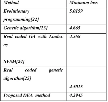
&4. And in the Table 5 shows clearly that proposed algorithm powerfully reduce the real power losses
when compared to other given algorithms. The optimal values of the control variables along with the
minimum loss obtained are given in Table 1. Equivalent to this control variable setting, it was found
that there are no limit violations in any of the state variables.
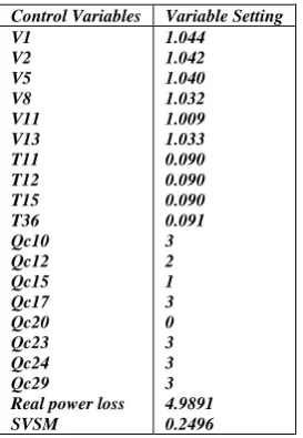
Table1.Results of DEA – ORPD optimal control variables
Control variables Variable setting V1 V2 V5 V8 V11 V13 T11 T12 T15 T36 Qc10 Q12 Qc1 Qc17 Qc20 Qc23 Qc24 Qc29
ORPD including voltage stability constraint problem was handled in this case as a multi-objective
optimization problem where both power loss and maximum voltage stability margin of the system were
optimized concurrently. Table 2 indicates the optimal values of these control variables. Also it is found
that there are no limit violations of the state variables. It indicates the voltage stability index has
increased from 0.2485 to 0.2496, an advance in the system voltage stability. To determine the voltage
security of the system, contingency analysis was conducted using the control variable setting obtained
in case 1 and case 2. The Eigen values equivalents to the four critical contingencies are given in Table
3. From this result it is observed that the Eigen value has been improved considerably for all
contingencies in the second case.
Table 2.Results of DEA -Voltage Stability Control Reactive Power Dispatch Optimal Control Variables
Control Variables Variable Setting V1 V2 V5 V8 V11 V13 T11 T12 T15 T36 Qc10 Qc12 Qc15 Qc17 Qc20 Qc23 Qc24 Qc29
Real power loss SVSM 1.044 1.042 1.040 1.032 1.009 1.033 0.090 0.090 0.090 0.091 3 2 1 3 0 3 3 3 4.9891 0.2496
Table 3. Voltage Stability under Contingency State
Table 4. Limit Violation Checking Of State Variables
Sl.No Contingency ORPD
Setting
VSCRPD
Setting
1 28-27 0.1410 0.1440
2 4-12 0.1658 0.1671
3 1-3 0.1774 0.1783
4 2-4 0.2032 0.2051
State variables
limits
ORPD VSCRPD
Lower upper
Q1 -20 152 1.3422 -1.3269
Q2 -20 61 8.9900 9.8232
Q5 -15 49.92 25.920 26.001
Q8 -10 63.52 38.8200 40.802
Q11 -15 42 2.9300 5.002
Table 5. Comparison of Real Power Loss
Method Minimum loss
Evolutionary programming[22]
5.0159
Genetic algorithm[23] 4.665
Real coded GA with Lindex
as
SVSM[24]
4.568
Real coded genetic
algorithm[25]
4.5015
Proposed DEA method 4.3945
Q13 -15 48 8.1025 6.033
V3 0.95 1.05 1.0372 1.0392
V4 0.95 1.05 1.0307 1.0328
V6 0.95 1.05 1.0282 1.0298
V7 0.95 1.05 1.0101 1.0152
V9 0.95 1.05 1.0462 1.0412
V10 0.95 1.05 1.0482 1.0498
V12 0.95 1.05 1.0400 1.0466
V14 0.95 1.05 1.0474 1.0443
V15 0.95 1.05 1.0457 1.0413
V16 0.95 1.05 1.0426 1.0405
V17 0.95 1.05 1.0382 1.0396
V18 0.95 1.05 1.0392 1.0400
V19 0.95 1.05 1.0381 1.0394
V20 0.95 1.05 1.0112 1.0194
V21 0.95 1.05 1.0435 1.0243
V22 0.95 1.05 1.0448 1.0396
V23 0.95 1.05 1.0472 1.0372
V24 0.95 1.05 1.0484 1.0372
V25 0.95 1.05 1.0142 1.0192
V26 0.95 1.05 1.0494 1.0422
V27 0.95 1.05 1.0472 1.0452
V28 0.95 1.05 1.0243 1.0283
V29 0.95 1.05 1.0439 1.0419
V30 0.95 1.05 1.0418 1.0397
7. Conclusion
In this DEA algorithm is used to solve optimal reactive power dispatch problem by taking
into consideration of various generator constraints. The projected method formulate reactive
power dispatch problem as a mixed integer non-linear optimization problem and establish
control strategy, with continuous and discrete control variables such as generator bus voltage,
reactive power generation of capacitor banks and on load tap changing transformer tap
position. The performance of the planned algorithm has been established well through its
voltage stability evaluation by modal analysis and is effectual at various instants following
system contingencies. The effectiveness of the proposed method has been demonstrated on
IEEE 30-bus system. Simulation results shows that Real power loss has been considerably
reduced and voltage profile index within the particular limits.
8. Nomenclature:
NB number of buses in the system
Ng number of generating units in the system
tk tap setting of transformer branch k
Psl real power generation at slack bus
Vi voltage magnitude at bus i
Pi,Qi real and reactive powers injected at bus i
Pgi,Qgi real and reactive power generations at bus i
Gij,Bij mutual conductance and susceptance between bus i and j
Gii,Bii self conductance and susceptance of bus i
θij voltage angle difference between bus i and j
References
[1] O.Alsac, and B. Scott, “Optimal load flow with steady state security”,IEEE Transaction. PAS
-1973, pp. 745-751.
[2] Lee K Y ,Paru Y M , Oritz J L –A united approach to optimal real and reactive power dispatch ,
IEEE Transactions on power Apparatus and systems 1985: PAS-104 : 1147-1153
[3] A.Monticelli , M .V.F Pereira ,and S. Granville , “Security constrained optimal power flow with
post contingency corrective rescheduling” , IEEE Transactions on Power Systems :PWRS-2, No. 1,
pp.175-182.,1987.
[4] Deeb N ,Shahidehpur S.M ,Linear reactive power optimization in a large power network using the
decomposition approach. IEEE Transactions on power system 1990: 5(2) : 428-435
[5] E. Hobson ,’Network consrained reactive power control using linear programming, ‘ IEEE
Transactions on power systems PAS -99 (4) ,pp 868-877, 1980
[6] K.Y Lee ,Y.M Park , and J.L Oritz, “Fuel –cost optimization for both real and reactive power
dispatches” , IEE Proc; 131C,(3), pp.85-93.
[7] M.K. Mangoli, and K.Y. Lee, “Optimal real and reactive power control using linear programming”
, Electr.Power Syst.Res, Vol.26, pp.1-10,1993.
[8] S.R.Paranjothi ,and K.Anburaja, “Optimal power flow using refined genetic algorithm”,
Electr.Power Compon.Syst , Vol. 30, 1055-1063,2002.
[9] D. Devaraj, and B. Yeganarayana, “Genetic algorithm based optimal power flow for security
enhancement”, IEE proc-Generation.Transmission and. Distribution; 152, 6 November 2005.
[10] C.A. Canizares , A.C.Z.de Souza and V.H. Quintana , “ Comparison of performance indices for
detection of proximity to voltage collapse ,’’ vol. 11. no.3 , pp.1441-1450, Aug 1996 .
[11] Kaveh A, Kalatjari V. Genetic algorithm for discrete sizing optimal design of trusses using the
force method, International Journal for Numerical Methods in Engineering, 55(2002) 55–72.
[12] Salajegheh E, Gholizadeh S. Optimum design of structures by an improved genetic algorithm
using neural networks, Advances in Engineering Software, 36(2005) 757–67.
[13] Gholizadeh S, Salajegheh E. Optimal design of structures for time history loading by swarm
intelligence and an advanced met model, Computer Methods in Applied Mechanics and Engineering,
198(2009) 2936–49.
[14] Kaveh A, Talatahari S. A hybrid particle swarm and ant colony optimization for design of truss
structure, Asian Journal of Civil Engineering, 9(2008) 329-48.
[15] Camp CV, Bichon BJ. Design of space trusses using ant colony optimization, Journal of Structural
Engineering, 130(2004) 741–51.
[16] Camp CV, Bichon BJ, Stovall SP. Design of steel frames using ant colony optimization, Journal of
Structural Engineering, 131(2005) 369–79.
[17] A. Kaveh , N. Farhoudi A new optimization method: Dolphin echolocation, Advances in
Engineering Software 59 (2013) 53–70.
[18] Griffin DR. Listening in the dark: the acoustic orientation of bats and men. New Haven (CT),
Cambridge (MA): Yale University Press, Biological Laboratories, Harvard University; 1958. p. 413.
[19] Au WWL. The sonar of dolphins. New York: Springer; 1993.
[20] May J. The greenpeace book of dolphins. Greenpeace Communications Ltd.; 1990.
[21] Thomas JA, Moss CF, Vater M. Echolocation in bats and dolphins. University of Chicago Press;
2002.
[22] Wu Q H, Ma J T. Power system optimal reactive power dispatch using evolutionary programming.
IEEE Transactions on power systems 1995; 10(3): 1243-1248
[23] S.Durairaj, D.Devaraj, P.S.Kannan ,’ Genetic algorithm applications to optimal reactive power
dispatch with voltage stability enhancement’ , IE(I) Journal-EL Vol 87,September 2006.
[24] D.Devaraj ,’ Improved genetic algorithm for multi – objective reactive power dispatch problem’
European Transactions on electrical power 2007 ; 17: 569-581.
[25] P. Aruna Jeyanthy and Dr. D. Devaraj “Optimal Reactive Power Dispatch for Voltage Stability
Enhancement Using Real Coded Genetic Algorithm” International Journal of Computer and Electrical
Engineering, Vol. 2, No. 4, August, 2010 1793-8163.
K.Lenin has received his B.E., Degree, electrical and electronics engineering in 1999 from university of madras, Chennai, India and M.E., Degree in power systems in 2000 from Annamalai University, TamilNadu, India. Presently pursuing Ph.D., degree at JNTU, Hyderabad,India.
Bhumanapally. RavindhranathReddy, Born on 3rd September,1969. Got his B.Tech in Electrical & Electronics Engineering from the J.N.T.U. College of Engg., Anantapur in the year 1991. Completed his M.Tech in Energy Systems in IPGSR of J.N.T.University Hyderabad in the year 1997. Obtained his doctoral degree from JNTUA,Anantapur University in the field of Electrical Power Systems. Published 12 Research Papers and presently guiding 6 Ph.D. Scholars. He was specialized in Power Systems, High Voltage Engineering and Control Systems. His research interests include Simulation studies on Transients of different power system equipment.
M. Surya Kalavathi has received her B.Tech. Electrical and Electronics Engineering from SVU, Andhra Pradesh, India and M.Tech, power system operation and control from SVU, Andhra Pradesh, India. she received her Phd. Degree from JNTU, hyderabad and Post doc. From CMU – USA. Currently she is Professor and Head of the electrical and electronics engineering department in JNTU, Hyderabad, India and she has Published 16 Research Papers and presently guiding 5 Ph.D. Scholars. She has specialised in Power Systems, High Voltage Engineering and Control Systems. Her research interests include Simulation studies on Transients of different power system equipment. She has 18 years of experience. She has invited for various lectures in institutes.