IJSRSET1844224 | Received : 20 March | Accepted : 31 March 2018 | March-April-2018 [(4) 4 : 962-966]
109
Harmonic Compensation using Coordinated Control of Dual
Interfacing Converters at Microgrid
D. Agila, D. Anbukkarasi, A. Barathi, M. Sujith*
Department of EEE, IFET College of Engineering, Villupuram, Tamilnadu, India
ABSTRACT
In distribution systems, there will be sudden increase or decreases in the load similar to nonlinear load .The load draws non-sinusoidal currents from the AC mains and these causes the load harmonics and reactive power, and excessive neutral currents that pollute power systems. Most of the power quality issues are created by nonlinear characteristics and fast switching of power electronic devices. A single distribution generation interfacing converters are generally used for harmonic compensation in DG but this may cause amplification of supply voltage harmonics when the system is connected to a sensitive load. In this paper we proposed a compensation strategy in which to shunt interfacing converters are used, first one for voltage harmonic suppression and the second one for current harmonic suppression that resulted due to the interaction between the first interfacing converter and the local nonlinear load
Keywords: Voltage Disturbances, Nonlinear Loads, PCC, Power Quality, Shunt Active Power Filter.
I.
INTRODUCTION
The usage of renewable energy resources has popularized due to the increased advantages. The advantages of renewable energy include the low or nil cost of fuel, pollution free, improved efficiency. The great potential of such resources for green energy production has led the technological society to the implementation of a new type of distribution system, the microgrid. There is one major challenge in implementation of distributed generation. For the interfacing of Renewable Energy Resources (RES) to the distributed system requires power electronics devices. Therefore power electronics devices play a vital role in the integration of the Renewable Energy system to the Distributed System which has the advantages of fast voltage and frequency regulation. The major disadvantage of using power electronics devices is that the switching operation of the semiconductors employed in the inverters causes voltage and current harmonic distortion to the grid.
possibility of amplification of supply voltage harmonics. Therefore we need simultaneous mitigation of the grid current and the supply voltage harmonics. So in this paper we proposed technique in which two shunt interfacing converters are used. The first converter is used for voltage harmonic mitigation. There arise current harmonic due to the interaction between the first interfacing converter and the local nonlinear load. The second converter is employed for the current harmonic compensation that resulted due to the interaction of first interfacing converter with the local nonlinear load. The current reference is to be generated for closed loop control. For this purpose we require high bandwidth inner loop controllers. The commonly used controllers include resonant controllers, predictive controller, and hysteretic controller. The hybrid voltage and current control is used to realize a fundamental voltage control for DG power regulation and a harmonic current control for local load harmonic compensation. The hybrid controller allows an interfacing converter to compensate harmonics in both grid-tied and islanding micro grids [6].
II.
HARMONICS IN MICROGRID
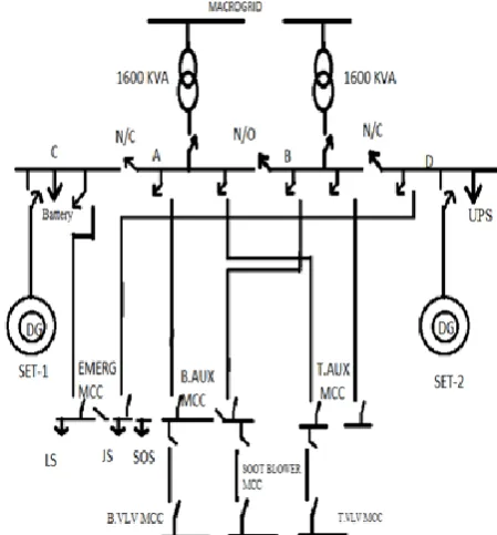
In every Thermal power plant there is an emergency plant is diesel power plant. It is also used for giving supply to the protection equipment and auxiliary units even when the station is tripped off. The local generation is occurs through the diesel power plant and the energy is stored in the battery. In power plants the loads are protective equipment and auxiliary units. The protective equipment and auxiliary units are seal oil system, lube oil system, jack oil system, battery charger, UPS system. It is necessary to run these systems. The seal oil system is necessary to run continuously because it seal the hydrogen gas inside the generator. And the turbine has to rotate in the minimum speed even when the station is tripped off. The circuit diagram of diesel set which is connected to the thermalpower plant shown in Figure 1
Figure 1. Schematic diagram of emergency power plant
Where as
LS - Lubrication system JS - Jack oil
SOS - seal oil system
MCC - Motor control cubical B.AUX - Boiler Auxiliary T.AUX - Turbine Auxiliary
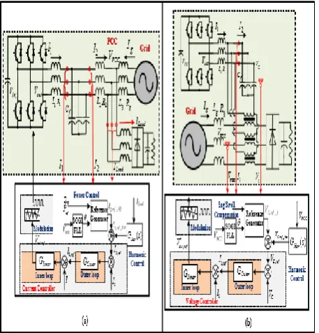
Figure 2. Harmonic compensation using shunt and series interfacing converters
III.
EXISTING SYSTEM
In the existing system the voltage and current harmonics are compensated separately. The current harmonics are compensated by the shunt interfacing converters and the voltage harmonics is compensated by series interfacing converters.
A) Shunt Interfacing Converter for Current Harmonic Mitigation
A shunt active power filter is a controlled current source which injects a compensating current depending upon the load current. The active power filters are used to filter out both higher and lower order harmonics in the power system. In the self-controlled dc bus the shunt active power filter and STATCOM(reactive power compensator of power transmission system)have the similar characteristics. It inject the harmonic compensating current of same magnitude as the load current harmonics ,but shifted in phase by 180° and thus compensates load current harmonics.
B) Series Interfacing Converters for Supply Voltage Harmonic Mitigation
Even when the harmonic current is compensated, there is supply voltage harmonics present in the system. This also causes the steady-state harmonic distortions in the grid. The harmonic voltage at PCC is same as the harmonics from the main grid in this case. A DVR is a series-connected solid-state device that injects voltage into the system in order to regulate the load side voltage. It is in a distribution system between the supply and a critical load feeder at the point of common coupling (PCC).Its function is to rapidly boost up the load -side voltage in the event of voltage sag in order to avoid any power disruption to that load. Therefore, a series DVR can be connected in series to the power distribution network using a series-connected matching transformer. The secondary of the transformer is connected to a converter with output LC filter. The voltage at PCC is measured by the DVR controller and the harmonic PCC voltage components are separated from the fundamental component.
IV.
PROPOSED SYSTEM
In the proposed, the supply voltage and the grid current harmonics are mitigated simultaneous by using the compensation methods. The compensation method using coordinate control of two parallel interfacing converters.
Figure 3. Circuit Diagram Proposed Dual Interfacing converter
enhanced by controlling the harmonic component of interfacing converter1. Meanwhile, the grid current harmonic is mitigated via the power conditioning through interfacing converter2. The converters used here are two leg three phase converter. The capacitors used reduce the switching losses. The output of the converters will have filters. Ig represents the grid current at the Point of Common Coupling (PCC). The output current of the converter 1 and converter 2 is represented by I1c1, I1,c2. The output current from the filter circuit is represented by I2,c1, I2,c2. The injected current by the converter is represented by Iinj. The harmonic component is compensated by the injected current. The amount of current that needed to be injected is computed by the control strategy. The gating circuit is controlled by the Pulse Width Modulation technique. The pulses are generated with the help of the PI controller. The PI controller generates gating signal such that the current injected is equal in magnitude to the harmonics present in the system but injected with phase opposition. Therefore, the injected voltage and current will cancel out the voltage and current harmonics. Thus reduces the current and voltage harmonics.
V.
CONTROL STRATEGY
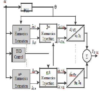
The harmonics elimination unit mainly consists of two major blocks – the harmonics estimation block and the harmonics injection block. Efficient and effective harmonics estimation and harmonics elimination methods are used for phase detection and harmonic component estimation. As the existence of the harmonics affect the PLL accuracy, the first stage is used to eliminate the harmonics from the sampled grid signal ensuring accuracy of the PLL. The second stage provides fast and accurate harmonics estimation as the PLL produces an accurate phase
Figure 4. Block diagram of control strategy
The grid current and the voltage at the PCC are fed to the phase locked look (PLL) block. The PLL block extracts the phase of the fundamental component. Then, using the PLL output, the third, fifth harmonics of these signals are estimated. The components of the estimated harmonics are sent to the harmonics injection block which decides how much voltage at the harmonic should be injected into the line based on the error between the actual and reference.
VI.
SIMULATION RESULTS
The proposed method is simulated using MATLAB/SIMULINK software. The Sim Power Systems package is used for the simulation of the inverters incorporating the proposed control algorithms. The output voltage waveform before harmonic compensation and after harmonic compensation using dual interfacing converter is obtained
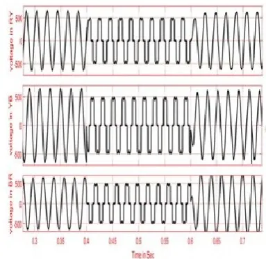
Figure 5. Distorted voltage waveform
In the simulation, a non linear load that introduces a distortion is connected to the grid. The THD of grid voltage becomes 29.31% and THD of the grid current becomes 8.83%. Using the coordinated control of parallel converters, it can be seen that the grid current is sinusoidal. The THD of the grid current becomes 4.17% after the compensation and also the THD of the grid voltage becomes 7.87%.
Figure 6. Distorted current waveform
The FFT analysis is carried out in the MATLAB and following results are obtained. It is seen that THD of the grid current is reduced from 8.83% to 4.17%.
Figure 7. FFT analysis of grid current before compensation
Figure 8. FFT analysis of grid current after compensation
The THD of the grid voltage is reduced form 29.31% to 7.87%. Thus, a significant reduction in the voltage harmonics can be obtained.
Figure 9. FFT analysis of grid voltage before compensation
VII.
CONCLUSION
The harmonic compensation by coordinated control of Dual Interfacing Converter gives better solution to the power quality issues in microgrid. The major advantage of this method is that it provides simultaneous voltage and current harmonics compensation.
The experimental results also have given a better power quality profile. The simulation of this harmonic compensation method is done by using MATLAB software. The results obtained shows that the THD has been significantly reduced by using this Dual Interfacing Converter. Thus, this method of harmonic compensation proves to be a best solution for the microgrid operated both at grid connected and islanded mode of operation.
VIII.
REFERENCES
[1].B.Singh,K.AI-Haddad,and A.Chandra,"A review of active filters for power quality improvement," IEEE Trans.Ind.Electron.,vol.46,no.5,pp.960– 971,May 1999.
[2].P.Acuna,L.Moran, M.Rivera, J.Dixon,and J.Rodriguez, "Improved active power filter performance for renewable power generation systems," IEEE Trans. Power Electron., vol.29,no.2,pp.687–694, Feb.2013.
[3].Y.W.Li,F.Blaabjerg, D.M.Vilathgamuwa,and P.C.Loh, "Design and comparison of high performance stationary-frame controllers for DVR implementation," IEEE Trans.Power Electron., vol.22,no.2, pp.602–612, Mar.2007. [4].C.Meyer, R.W.DeDoncker, Y.W.Li,and
F.Blaabjerg, "Optimized control strategy for a medium-voltage DVR-Theoretical investigations and experimental results," IEEE Trans.Power Electron.,vol.23,no.6,pp.2746–2754,Nov.2008. [5].F.Blaabjerg,Z.Chen,and S.B.Kjaer,"Power
electronics as efficient interface in dispersed
power generation systems," IEEE Trans.Power Electron., vol.19,no.5,pp.1184–1194,Sep.2004.
[6]. Sujith Mayakrishnan, Padma Srinivasan,