e-ISSN: 2278-067X, p-ISSN: 2278-800X, www.ijerd.com
Volume 10, Issue 7 (July 2014), PP.76-80
Determine Aerodynamic Characteristic for FX63-137 Aerofoil
Magedi Moh. M. Saad
1, Norzelawati Asmuin
2, Abass Bin Abdul wahab
3University Tun Hussein Onn Malaysia (UTHM), Parit Raja, 86400 Batu Pahat, Johor.
Abstract:- this paper mainly concentrated on determine aerodynamic characteristic for FX63-137 aerofoil experimentally and by computer aided to choose best angle of attack at maximum lift low drag. This paper divided into many stage, Firstly manufacturing aerofoil using aluminium alloy with using CNC machine ,secondly Testing process using subsonic wind tunnel ,finally display results at low Reynolds number at speed of 20m/s, 30m/s in chart and compare this results with reference and select best angle of attack at maximum lift.
Keywords:- Aerofoil, Wind Tunnel, lift, Drag, angle of attack, XFOIL.
I.
INTRODUCTION
As aerofoil become more efficient and reliable, they are also becoming more complicated. This can be seen when calculating the aerofoil characteristics for a certain airplane, for example. Integrated systems design now takes the focus in any new aircraft development project. Complex systems modelling require accurate knowledge of subsystem and component performance.[1] Although engineers can manage to get component performance predictions using practical experiments, these test programs can be very expensive.[2] The range of this operating system, characterized by the range of operating conditions (which include inlet pressures, flow rates, altitude and many others), continues to increase as companies extend the use of each aircraft component.[4]
In this paper will be describe the aerodynamic features of an aerofoil at low Reynolds number. Literature survey related to wind tunnel that is used for aerofoil testing is also discussed and computational simulation using XFOIL program. And will previous research relating to the aerodynamic characteristics of the airfoil are described in feature.[3]
II.
AEROFOIL
OPTIMIZATION
Aerofoil design is considered an important factor in the manufacture of this type of aircraft. So this type of aircraft need high coefficient of lift because needs to take off within 100 feet.[3] Therefore, we will test this aerofoil with minimal drag on at speed about 30 m/s. in this case we need to low Reynolds number.
III.
AEROFOIL
DESIGN
The Airfoil data at low Reynolds number from seldom get it. However would be found airfoil performance at low Reynolds numbers for airfoil (FX 63-137). [5]For maximum endurance must obtain the best design for the wing because he is one of the fundamental factors and the essential for that.
We chose FX 63-137 because it is superior in aerodynamics characteristics at low Reynolds number and at Low Speed. This airfoil has characteristic high lift coefficient where reach about 1.6, this property not found in other aerofoils. Figure1: shows the FX 63-137 airfoil. [6]
Fig.1: FX63-137 Aerofoil [3]
IV.
PRINCIPLE
OF
AERODYNAMIC
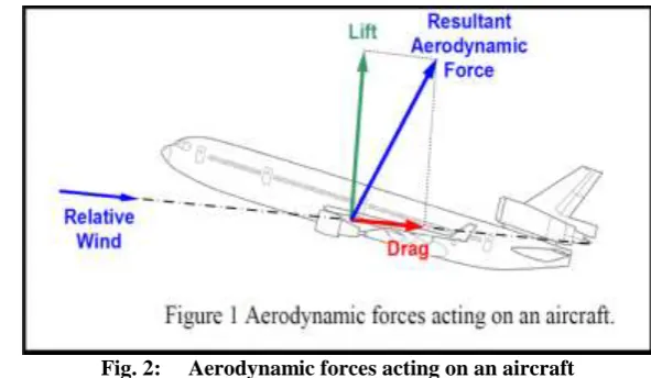
Aircraft performance depends on the effectiveness of the wing, which is measured by lift to drag ratio. The lift to drag ratio for all aircraft not associated with wing drag only but includes also drag contributed by the rest of the aircraft.
Fig. 2: Aerodynamic forces acting on an aircraft
A. Lift Force
Of the key factors affecting the endurance is the lift force in the plane of symmetry in the direction perpendicular to the flight line. Lift force has to be balanced by the aircraft weight for steady level flight and must has to be balanced with the aircraft weight the lift is stated as follows.
(1)
Where L is the lift force, ρ is the air density, V is the air velocity, S is the reference area and CL is the lift coefficient. [2]
The dominant factor on conventional aircraft is the lift coefficient that was created from the wing. Tail and fuselage also contributes to the lift generation but in a few percentages, but vertical and horizontal tail functions control stability and will provide a negative lift or down force.
The generation of lift is achieved by producing a greater pressure at the lower surface than upper surface of the body. The difference of the pressure is achieved when the airspeed at the upper surface is higher compared to the lower surface. Inclination of the body relative to the air flow, also contributes to the lift. Lift coefficient measures how efficiently the wing is changing velocity into lift. The higher lift coefficient indicates an efficient airfoil design. The formula of lift coefficient is:
(2)[6]
B. Drag Force
Drag is one of the important factors that affect the plane with extended region of separated flow. when the vehicle produces a lift there are drag is called induced drag. The total of form drag and skin friction is called viscous or profile drag.
In general, drag is a force that causes a resistance in motion. It is the force developed parallel to the relative wind, and is defined as:
(3)
Where D is the drag force, ρ is the air density, V is the air velocity, S is the reference area and CD is the drag coefficient. The aerodynamic drag can be defines as the sum of the tangential or skin friction force and the normal or pressure forces parallel to but in the opposite direction of the vehicle’s velocity vector. . The drag coefficient is expressed as:
(4)
C. Reynolds Number
velocity and low kinematics viscosity. When aircraft design take in your mind scale effect and as an index to predict various types of flows from during calculate Reynolds number. The formula of Reynolds number as:
(5)[8]
Where ρ is the density of air, V is the mean velocity of air, l is the characteristics length, and μ is the coefficient of viscosity.
V.
MANUDACTURING
AIRFOIL
FX63-137
These steps carried in the CNC machine is VERTICAL CENTER NEXUS 410A-II (MATRIX CAM) workshop of the UTHM University:
Create AutoCAD file version 2007 and exported to the machine program. Select Set and Program Edit to check form final shape.
After the completion of manufacturing pieces airfoil as shown.
Fig3: Final shape of aerofoil before fixated together
After prepare slot at quart airfoil with diameter 1.1 Cm prepare rod with same diameter and with length 67.3 Cm (45 cm inside aerofoil).
Passes the rod inside the aerofoil to connect all pieces together and to fix the rod in the aerofoil.[9]
VI.
TESTING
THE
WING
WITH
SUBSONIC
WIND
TUNNEL
Switch on the electrical isolator on the Control and Instrumentation Frame. Press the red START button.
Set the speed control to the minimum position (fully anticlockwise).
Gradually turn the speed control clockwise until the tunnel is operating at the speed needed for the experiment.[10]
Table1: Mach number and Reynolds number at different flow speed Speed (m/s) Mach number Reynolds number
20 0.0589 2.0073 x 10⁵
30 0.0883 3.011x 10⁵
VII.
XFOIL
PROGRAM
a) Draw FX63-137 aerofoil data to a text file and save with .DAT extension.
b) This DAT file containing the data, export file into XFOIL software to calculate characteristics about the airfoil.
c) Write Mach number and Reynolds number and specify angle of attack.[12]
VIII.
RESULTS
AND
COMPARATIVE
After determine results with subsonic wind tunnel and XFOIL computer aided design, can be display and compare results to identify best angle of attack and the best lift coefficient for each speed.
Fig4: CL-α slope for U=20 m/s Fig5: CL-α slope for U=30 m/s
Fig6: CD polar for U=20 m/s Fig7: CD polar for U=30 m/s
XI.
CONCLUSION
AND
FUTURE
WOR
Through previous studies found that the lift coefficient of approximately 1.6. To get a successful design and with good effectiveness must be a high coefficient of lift and low drag coefficient.[13]
REFERENCES
[1]. Park, K., Han, J. W., Lim, H. J., Kim, B. S., & Lee, J. (2008). Optimal Design of Airfoil with High Aspect Ratio in Unmanned Aerial Vehicles. International Journal of Mechanical, Industrial, and Aerospace Engineering, 2(1), 66-72.
[2]. Caughey, David A. (2011). "Introduction to Aircraft Stability and Control Course Notes for M&AE 5070.".
[3]. Zhang, Z., Zhang, Y.-c., Li, J. & Wang, J. (2011). Aerodynamic analysis method of heavy-duty commercial vehicle based on CFD, at. Paper read at Electric Information and Control Engineering (ICEICE), 2011 International Conference on: 4756-4759.
[4]. Jianjun, Q., Yi, M. & Mingwei, X. (2011 ). Investigation on Performance Influence of Maximum Thickness Position on Vertical Axis Wind Turbine Airfoil, at. Paper read at Power and Energy Engineering Conference (APPEEC), Asia-Pacific: 1-4. 25-28.
[5]. Mustafa Cavcar. (2004) Anadolu University, School of Civil Aviation Eskisehir, Turkey,’’Aerodynamic Forces and Drag Polar’’.
[6]. Parrish, Jeff, and Micah Cooper. (2008). "A framework for integrated flight simulation and design." Proceedings of the 46th Annual Southeast Regional Conference on XX. ACM.
[7]. K. Dmitri. (2010). ’’A Guide to Numerical Methods for Transport Equations’’. [8]. D, Selig and Fraser All rights reserved. (2011). ‘’AIRFOILS AT LOW SPEEDS’’.
[9]. A. Gustafson.(2011). ‘’Design, Simulation, and Wind Tunnel Verification of a Morphing Airfoil’'. Thesis submitted to the Faculty of the Virginia Polytechnic Institute and State University in partial ful_llment of the requirements for the degree of Master of Science In Mechanical Engineering.
[10]. T. J. Blackwell (2011). SUBSONIC WIND-TUNNEL WALL CORRECTIONS ON A WING. Diss. San Jose State University.
[11]. Allan, Brian G., Greg S. Jones, and John C. Lin. (2011). "Simulation of a 2D Wind Tunnel Experiment." 49th AIAA Aerospace Sciences Meeting Including the New Horizons Forum and Aerospace Exposition, AIAA Paper. Vol. 25.
[12]. Pletcher, Richard H., (2012). Dale Arden Anderson, and John C. Tannehill.Computational fluid mechanics and heat transfer. CRC Press.