IJIRT 143261 INTERNATIONAL JOURNAL OF INNOVATIVE RESEARCH IN TECHNOLOGY 95
Encrypted Data Concealment in Encrypted Images
Asst. Prof. A.S. Deshpande 1, Bhagyashri S. Jatte 2
1
Asst. Professor,2Student
1,
Electronics & comm. Department,
JSPM’s Imperial college of Engineering Wagholi, Pune, India
Abstract— The paper proposes the enhancement of protection system for secret data communication through encrypted data concealment in encrypted images. The image is then separated into various blocks locally and lifting wavelet transform is used to detect
approximation and detailed coefficients. Then
approximation part is encrypted using chaos encryption method. The proposed encryption technique uses the key to encrypt an image and enhances the safety of secret carrier information by making the information inaccessible to any intruder having a random method. After image encryption, the data hider will conceal the secret data into the detailed coefficients which are reserved before encryption of approximation part. Although encryption achieves certain security effects, they make the secret messages unreadable and unnatural or meaningless. This system is still enhanced with encrypt messages using an asymmetric key method. This is the reason a new security approach called reversible data hiding arises. It is the art of hiding the existence of data in another transmission medium to achieve secret communication. The data hiding technique uses the adaptive LSB replacement algorithm is used for concealing the secret message bits into the encrypted image. In the data extraction module, the secret data will be extracted by using relevant key for choosing the encrypted pixels to extract the data. By using the decryption keys, the image and extracted text data will be decrypted from encryption to get the original information. Finally the performance of this proposal in encryption and data hiding will be analyzed based on image and data recovery.
Index Terms—Image Encryption, Data Hiding, Chaos Encryption Technique, LSB method, etc.
I. INTRODUCTION
Steganography is manner to conceal secrete data into other innocent data. Data concealment is expressed to as a process to hide data in cover media. The data hiding process links two sets of data, a set of the embedded data and another set of the cover
media data. For instance, in secret communications, the hidden data may often be irrelevant to the cover media. In authentication, however, the embedded data are closely related to the cover media. In these two types of applications, invisibility of hidden data is an important requirement. An image containing a secrete data is named cover image. Digital images are perfect for hiding secrete information. First, the transformation of cover images in addition to steganographic image should be visually unreadable or meaningless. Second, the message hiding method has to be reliable. Hence no hackers will try to extract the data illegally. It is challenging for somebody to extract that concealed message if one doesn’t have a superior extracting technique and an appropriate secret key. Third, the extreme size or length of the secret message that we are going to conceal should be lengthier.
IJIRT 143261 INTERNATIONAL JOURNAL OF INNOVATIVE RESEARCH IN TECHNOLOGY 96
adaptive LSB replacement algorithm for concealing the secret message bits into the encrypted image. In the data extraction module, the secret data will be extracted by using relevant key for choosing the encrypted pixels to extract the data. By using the decryption keys, the image and extracted text data will be extracted from encryption to get the original information.
Fig.1 Block diagram of non-separable reversible data hiding in encrypted image.
Since losslessly vacating room from the encrypted images is relatively difficult. If we reverse the order of encryption and vacating room, i.e., reserving room prior to image encryption at content owner side, the RDH tasks in encrypted images would be more natural and much easier which leads us to the novel framework, “reserving room before encryption (RRBE)”. Finally the performance of this proposal in encryption and data hiding will be analyzed based on image and data recovery. Data Protection system for secret data transmission based on, Reversible encrypted data concealment in encrypted images using chaos encryption, Asymmetric key encryption and adaptive least significant bit replacement technique. Methodologies used are Lifting Wavelet Transformer, Chaos based image encryption. Asymmetric key algorithm based text encryption, Adaptive LSB Replacement, Data Recovery by decryption, Parameter Analysis (MSE, PSNR, Correlation, Elapsed time. Obviously, most of the existing data hiding techniques are not reversible.
II. PREVIOUS METHODS
Chaotic systems are very suitable for data message encryption because they have several good properties, for example, (a) chaotic motion is neither periodic nor convergent, and the domain is limited. With time passing, the points of the movement trace traverse all over domain, namely the ergodicity of the chaotic orbit; (b) the flexing and collapsing are
carried continually through the limited domain. Therefore the outputs of chaotic systems are very irregular, similar to the random noise; (c) because chaotic systems are extremely sensitive to their initial conditions, the movement of any two closed points can be separated in an exponent rule. The long-term movement trace of systems cannot be forecasted. These dynamics characteristics cause chaotic sequences to be wideband, pseudo-random, and unmasked hardly. Different chaotic sequences can be produced with the different initial values of the systems. Therefore, the encrypting space is very wide. Because chaotic sequences are easy to control and easy to regenerate, the possibility for encryption and decryption has been provided [4]. A relationship between chaotic systems and cryptosystems is given by Fridrich [3].
In recent years, many RDH techniques have emerged in recent years. Fridrich et al. [1] created a general framework for RDH. By initial extracting compressible choices of original cowl thus pressure them losslessly spare space is also saved for embedding auxiliary info. A further well-liked technique relies on distinction enlargement (DE) [3], throughout that the excellence of each component cluster is enlarged , e.g., magnified by 2, then the little quantity vital bits (LSBs) of the excellence unit of measurement all-zero and could be used for embedding messages. Another promising strategy for RDH is bar graph shift (HS) [4], throughout that space is saved for info embedding by shifting the bins of bar graph of gray values.
1. Choices of data concealment
1. The host signal need to be non-objectionably degraded and thus the embedded info need to be minimally perceptible. (The goal is for the knowledge to remain hidden. As any magician will tell you, it's potential for one issue to be hidden whereas it remains in plain sight; you simply keep the person from looking at it. We'll use the words hidden, inaudible, unperceivable, associated invisible to mean that Associate in nursing observer does not notice the presence of the knowledge, albeit they are perceptible.)
IJIRT 143261 INTERNATIONAL JOURNAL OF INNOVATIVE RESEARCH IN TECHNOLOGY 97
3. Asymmetrical secret writing of the embedded info is fascinating, since the aim of data concealment is to remain the knowledge at intervals the host signal, but not basically to create the knowledge powerful to access.
4. Error correction coding1 need to be accustomed guarantee info integrity. It's inevitable that there will be some degradation to the embedded information once the host signal is modified.
5. The embedded information need to be self-clocking or each that means re-entrant. This ensures that the embedded info is also recovered once exclusively fragments of the host signal unit of measurement out there, e.g., if a line is extracted from associate interview, info embedded at intervals the section is also recovered. This feature to boot facilitates automatic decoding of the hidden information, since there is not any need to be compelled to envision the initial host signal.
III. PROPOSED SCHEME
The proposed scheme combines the benefits provided by both systems mentioned above. As will be clear in the results, the first system based on Chebyshev chaotic sequence, is relatively simple and hence the time taken for the encryption process is very less. The proposed system as in the second system based on Logistic Map has two encryption stages. The first encryption stage uses a chaotic system that is based on the Logistic Map, but unlike the second system, the second encryption stage in the proposed system uses a discrete chaotic sequence based on Equation. (3).
=cos (n arc cos(x)) (1) It can be simply assumed
=2x (2) For n N, n ≥ 2, and x [-1, 1], every T n(x) is
chaotic.
The discrete orders of the chaotic dynamical scheme are attained by the following equation:
= ( ) (3) For n = 5, from Eq. (4.2) & Eq. (4.3), the following
relationship is established
= ( ) = (4) Where k = 0, 1, 2...
Selecting any initial value in [-1, 1], a discrete chaotic Chebyshev sequence by any length
{ } can be created using Equation. (4).
1. Discrete Chaotic Encryption
The Discrete Chaotic Encryption proposed is based on Chebyshev chaotic sequences. Chebyshev mapping is a simple mapping, and the n rank Chebyshev mapping can be described as given follows:
1.1 Encryption Process
If a digital picture e.g. A of size M x N pixels desires to be encrypted, a corresponding Chebyshev discrete chaotic encrypting algorithm of digital images is expressed as follows:
1. Arbitrarily select two values and in the interval [-1, 1].
2. Generate two sufficiently long Chebyshev chaotic sequence using Eq. (4.4) and and as the initial conditions. The lengths of the two orders must be much larger than M and N respectively.
3. Arbitrarily intercept two sequences of length M and N from the above two sequences respectively i.e.{ , ,……, } & { , ,……,
}
4. Rearrange the two orders obtained in stage 3 either in rising or descending order to get two new discrete chaotic sequences of length M and N respectively i.e. { , ,……, } & { , ,……, }
5. Decide the position of each in sequence and generate replacement address set S1={ , , … , }
6. Similarly decide the position of each y { , ,……, } in the sequence { , ,……, } to generate replacement address set S2= { }
7. The address set S1 is used in row scrambling of the pixels in the digital image.
8. Similarly, the second sequence S2 is used to scramble the columns of the digital image. The decrypting process of the image is the inverse process of the encryption.
2. Logistic Map Encryption
The basic Logistic-map is formulated as:
IJIRT 143261 INTERNATIONAL JOURNAL OF INNOVATIVE RESEARCH IN TECHNOLOGY 98
Where, x (0, 1)
The parameter µ and the initial value can be adopted as the system key (µ, ). The research result shows that the system is in chaos on condition that 3.569 < µ < 4.0. The encryption scheme is composed of two chaotic systems. One creates a binary stream and the other creates a permutation matrix P. First, the pixel values of the plain image are modified randomly using the binary stream by the traditional stream ciphers technology, namely bit-wise XOR operation. Then the improved image is encrypted again by matrix P.
2.1 Encryption Process of logistic map
Consider the plain image to be represented by A, and A (i, j) stands for an individual pixel in the image. The system key is denoted as k = ( , ) where, = ( , ) and = ( , ) are the initial conditions of the two chaotic systems respectively. The encrypting process consists of following five steps :
1. Generate a chaotic sequence using the sub-key as the initial conditions of k the first chaotic system.
2. Transform the chaotic sequence into a binary stream by a threshold function.
3. Modify pixel values of the plain image A (i, j) using the binary stream as a key stream and get the image A’ (i, j). The operation is bit-wise XOR.
4. Construct a permutation matrix P using the sub-key as the initial conditions of the second chaotic system.
5. Encrypt the image A’ (i, j) by permutation matrix P and get the encrypted image A” (i, j).
The encryption process is done in above algorithm. The decrypting process is the reverse process of encrypting.
3. Proposed Algorithm
The proposed scheme mixes the benefits delivered by both systems stated above. As will be clear in the results, the previous system created on Chebyshev chaotic order, is comparatively simple and therefore the time occupied for the encryption process is too less. The proposed system as in another system created on Logistic Map has two stages of
encryption. The previous encryption phase uses a chaotic system which is based upon the Logistic Map, and then unlike the next system, the second encryption stage in the suggested system uses a discrete chaotic sequence based on Equation. (4.4).
3.1 Encryption Algorithm
The key for encoding is denoted as k = ( , ), where = (µ, ) and = ( , ). The parameter ‘µ’ is selected as that 3.569 < µ < 4.0 and
(0, 1)
The initial conditions and for the chaotic system of the second stage occur in [-1, 1]. Consider the plain image to be represented by A of size M x N, and A (i, j) stands for an individual pixel in the image. The encrypting process consists of following steps:
1. Generate a chaotic sequence using the sub-key k1 as the initial conditions of the first chaotic system.
2. Transform the chaotic sequence into a binary stream by a threshold function.
3. Modify pixel values of the plain image A (i, j) using the binary stream as a key stream and get the image A’ (i, j). The operation is bit-wise XOR.
4. Generate two sufficiently long Chebyshev chaotic sequence using Equation. (4.3) and and as the initial conditions. The lengths of the two sequences should be much larger than M and N respectively.
5. Arbitrarily intercept two sequences of length M and N from the above two sequences respectively.
6. Rearrange the two sequences obtained in step 5 either in ascending or descending order to get two new discrete chaotic sequences of length M and N respectively.
7. Decide the position of each in sequence and generate replacement address set S1={ }.
8. Similarly decide the position of each { , ,……, } in the sequence { , ,……, } to generate replacement address set S2= { , … , }
IJIRT 143261 INTERNATIONAL JOURNAL OF INNOVATIVE RESEARCH IN TECHNOLOGY 99
pixels in the image encrypted in stage I. Similarly, the second sequence S2 is used to scramble the columns of the images encrypted in stage I.
3.2 Generation of Binary Stream
The process for generating the binary stream mentioned in step 2 of section 5.1 above is as follows:
1. Generate a chaotic sequence using the sub-key k1 as the initial conditions of the first chaotic system. i.e.
2. Generate a binary stream from the above chaotic system xi by using a threshold function F. The threshold function F is as given below:
F(x) = {00000000 0≤ x <
00000001 ≤ x < 00000010 ≤ x < ’ ’
11111111 ≤ x <1} (6)
4 Lifting Scheme of Wavelet Transform LWT is used to decompose the image into unlike subbands images, viz. LL, HH, LH, and HL to conceal the messages in the coefficients of image pixel of the subbands. The Lifting wavelet scheme is a simplest and efficient algorithm used to determine wavelet transforms. The established a lifting scheme used for the structure of bi-orthogonal wavelets Wim Sweldens. The important characteristic of this lifting wavelet scheme is such that all explanations are resulting in the type of spatial domain. This does not need complex precise calculations which are used in traditional methods. This does not respite on Fourier transforms. Lifting pattern of wavelet has used to create second invention wavelet; those are not essentially translation and dilation of single particular function. It was initiated as a method to progress a given DWT to obtain specific properties. Fig.2 Block diagram of LWT method Step1: Column wise processing to get H and L H= ) (7)
L=( −(H/2)) (8)
Where, and is the odd column and even column wise pixel values Step 2: Row wise processing to get LL, LH, HL and HH. Separate odd and even rows of H and L. Namely, - Odd row of H - Odd row of L - Even row of H - Even row of L LH= (9)
LL = − [LH / 2] (10)
HL = − (11)
HH = − [HL / 2] (12) Inverse Integer wavelet transform is formed
by Reverse lifting scheme (LWT). Procedure is similar to the forward lifting scheme.
5 LSB Insertion
IJIRT 143261 INTERNATIONAL JOURNAL OF INNOVATIVE RESEARCH IN TECHNOLOGY 100
Fig.3 the weighting arrangement of an 8-bit pixel
The weighting arrangement of an 8-bit pixel number is illustrated in Figure3 A chief benefit of the LSB system procedure is it is easy and quick. There is steganography software established which work nearby LSB color changes via palette manipulation. LSB insertion also works fine with gray-scale images. LSB substitution is very commonly used in steganography process, which is the technique of LSB substitution. In the gray level type image, each pixel contains of 8 bits. One image pixel may hence show =256 deviations.
IV EXPERIMENTAL RESULTS
In this dissertation work, secret data communication is done over unsecure channel based on image encryption and data hiding technique. Lifting wavelet transform is used to reserve space for concealing data. Chaos encryption is used to protect image contents. Using MATLAB software, above approaches is carried out. The outcomes are as follows.
The encryption algorithms of the three systems have been implemented in MATLAB 7.4. For the first system the initial conditions which also constitute the key for the encryption algorithm are: x0= 0.496264538324968 & y0 = -636856254848635. The results for the encryption process are shown below.
(a)
(b)
(c)
(d)
Fig.4. Results of Encryption using the Chaotic Encryption system based on Chebyshev Chaotic sequences (a) the plain image (b) its transformed image (c) image in which text is concealed and (d) its recovered image
As is seen in Figure 3, both the cipher images show a mesh pattern; a result of the row and column scrambling. For the second encryption scheme based on Logistic Map the system key or the initial conditions taken are as follows:
µ1 = 3.9, x01=0.400005674, µ2 = 4.0, x02 = 0.347834217;
IJIRT 143261 INTERNATIONAL JOURNAL OF INNOVATIVE RESEARCH IN TECHNOLOGY 101
encryption method are as displayed below in Figure 8.5, figure 8.6 and figure 8.7. Comparing Figure 8.1 with Figure 8.4, it can remain seen that there is not much difference in the encrypted images achieved by proposed techniques.
Input Text: Bhagyashri
Cipher or encoded Text: ¶Oå™xgj3˜% Decryption Text: BhagyashriÕ
10 15 20 25 30 35 40 45 50
0.005 0.01 0.015 0.02 0.025 0.03 0.035 0.04 0.045 0.05
Hiding Capacity(Hc)---->
M
S
E
-->
Hc Vs MSE
Fig. 5 Hiding Capacity vs. MSE
Figure 5 shows the graph of Hiding Capacity vs. MSE, in which as hiding capacity or data is to be hidden increases then Means square error of image also increases. Hiding capacity varies between 10 to 50 bpp. With increase in the hiding capacity MSE increases from 0.005 to 0.05.
10 15 20 25 30 35 40 45 50
61 62 63 64 65 66 67 68 69
Hiding Capacity(Hc)---->
P
S
N
R
--->
Hc Vs PSNR
Fig.6 PSNR vs. Hiding Capacity
Figure6 shows the PSNR vs. Hiding Capacity in which PSNR decreases with increase in hiding capacity of data in an image. The more is PSNR then hiding capacity is reversed because data to be hidden is also more. .Hiding capacity varies between 10 to 50 and PSNR increases from 61 to 69 with decrease in hiding capacity.
0.005 0.01 0.015 0.02 0.025 0.03 0.035 0.04 0.045 0.05 61
62 63 64 65 66 67 68 69
MSE---->
P
S
N
R
-->
MSE Vs PSNR
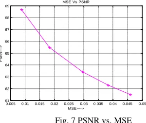
Fig. 7 PSNR vs. MSE
Figure 7 shows the graph of PSNR vs. MSE in which PSNR increases with decrease in MSE. More PSNR means that less is error because PSNR shows the peak error in images. The value of MSE and PSNR is estimated in above graph. MSE varies between 0.005 to 0.05 and PSNR increases from 61 to 69 with decrease in MSE.
The PSNR block work out the peak signal-to-noise ratio, in dB, amongst two images. The higher the PSNR, the better is the feature of the compressed or reconstructed image. The PSNR block computes the peak signal-to-noise ratio, in decibels, between two images. This ratio is often used as a quality measurement between the original and a compressed image. The higher is the PSNR, the better the quality of the compressed or reconstructed image.
To compute the PSNR, the segment first estimates the mean-squared error using the following equation: PSNR=10× (13) = 10× dB
The MSE and PSNR, both are the error metrics have used to match image compression quality. To compute the PSNR, the block first calculates the mean-squared error using the following equation.
MSE= (14) ‘ ’ means pixel value at position (i, j) in the cover
image and ‘ ’ means pixel value at same position in corresponding stego image.
5. Sample Text Encryption in an image and Recovery
IJIRT 143261 INTERNATIONAL JOURNAL OF INNOVATIVE RESEARCH IN TECHNOLOGY 102
Performance Metrics: Mean Square Error: 0.0062
Peak Signal to Noise Ratio: 70.1890 dB Correlation: -6.8914e-004
Elapsed time: 5.2649 Sec
The proposed scheme is thus able to successfully combine the benefits of the two reviewed chaos based encryption schemes viz. faster execution time of the first technique and higher de-correlating ability of the second technique.
V. CONCLUSION
The paper presents the protection of image and hidden data during transmission. The algorithm is based on reserving room technique approach and chaotic cryptographic system. The chaos encryption is used for protection of image contents while concealing procedure. The spatial domain of steganography is used because it gives better results in embedding capacity than transformation technique. In this, lifting wavelet transform is used to reserve extra space for hiding information effectively. After encrypting a message, the data is hidden using a LSB steganographic method which increases the embedding capacity. This technique is created the encrypted stego image with maximum data hiding capacity. In this way we can conceal a large size of data. The original image is recovered losslessly when embedded message extracted. This method satisfies the requirements such as hiding capacity and security which are estimated for data concealing. Moreover, when an attacker was to defeat the steganographic technique for detecting the message from the steganographic object, then he would still need the cryptographic deciphering key to decipher the encrypted message. The new algorithm and simulation results show that encryption and decryption are good and the algorithm has good security and robustness. The scheme has larger key space and is sensitive to the key. The scheme can resist most known attacks, such as brute-force attacks. The encryption scheme is faster than the one based just on Logistic Maps. So the proposed scheme is very suitable for the digital image encryption. Finally, the performance factors of system were evaluated with quality parameters such as means square error, PSNR factor and elapsed time. It is enhanced method which gives with better data hiding capacity rather than erstwhile methods.
REFERENCES
1] Kede Ma, Weiming Zhang, Xianfeng Zhao, Member, IEEE, Nenghai Yu, and Fenghua Li “Reversible data hiding in encrypted images by reserving room before encryption” IEEE Trans. On
Information Forensics and Security, Vol. 8, No. 3, March 2013
[2] Sanjeev Ghosh, Sangeeta Mishra, Payel Shaha,
“Chaos Based Technique for Digital Images”
ICWET’10, February 25-26, 2011, Mumbai, Maharashtra, India
[3] Thanikaiselvan, Arulmozhivarman. P, Rengarajan Amirtharajan, John Bosco Balaguru Rayappan, “Wave(Let) Decide Choosy Pixel Embedding for Stego” International Conference on
Computer, Communication and Electrical Technology – ICCCET2011, 18th & 19th March, 2011
[4] Po-Yueh Chen, Hung-Ju Lin, “A DWT Based
Approach for Image Steganography” International
Journal of Applied Science and Engineering
[5] J. Tian, “Reversible data embedding using a difference expansion,” IEEE Trans. Circuits Syst.
Video Technol., vol. 13, no. 8, pp. 890–896, Aug. 2003.
[6] X. L. Li, B. Yang, and T. Y. Zeng, “Efficient
reversible watermarking based on adaptive
prediction-error expansion and pixel selection” IEEE
Trans. Image Process., vol. 20, no. 12, pp. 3524– 3533, Dec. 2011.
[7] Xipeng Zhang, “Separable Reversible Data
Hiding in Encrypted Image” IEEE Trans. on
information forensic and security, vol. 7, No. 2, April 2012.
[8] L. Luo et al., “Reversible image watermarking using interpolation technique” IEEE Trans. Inf.
Forensics Security, vol. 5, no. 1, pp. 187–193, Mar. 2010.
[9]W. Zhang, B. Chen, and N. Yu, “Improving various reversible data hiding schemes via optimal
codes for binary covers” IEEE Trans. Image
Process., vol. 21, no. 6, pp. 2991–3003, Jun. 2012. [10] Wien Hong, Tung-Shou Chen, and Han-Yan Wu, “An Improved Reversible Data Hiding in
Encrypted Images by Using Side Match” IEEE Signal
IJIRT 143261 INTERNATIONAL JOURNAL OF INNOVATIVE RESEARCH IN TECHNOLOGY 103
IEEE Trans. Image Process., vol. 16, no. 3, pp. 721– 730, Mar. 2007.
[12] P. Tsai, Y. C. Hu, and H. L. Yeh, “Reversible image hiding scheme using predictive coding and histogram shifting” Signal Process., vol. 89, pp.