Aruna et al. World Journal of Engineering Research and Technology
www.wjert.org 44
KINEMATIC POSITION DETERMINATION USING GLOBAL
POSITIONING SYSTEM
Rashmi K1, Supriya S2, Pavan Kumar G A3, Sneha M B4 and Aruna M G5*
1,2,3,4
Students of CSE, M S Engineering College, 5
Associate Professor, Dept. of CSE.
Article Received on 29/10/2016 Article Revised on 18/11/2016 Article Accepted on 08/12/2016
ABSTRACT
The Global Positioning System (GPS) is a satellite-based navigation
system that consists of 24 orbiting satellites; each satellite revolves
around the Earth twice a day. With signals from four or more satellites,
a GPS receiver can triangulate its location on the ground (i.e.,
longitude and latitude) to determine the accurate kinematic position of the user by using GPS
satellites. The user’s position is computed using Newton-Raphson method in the Matlab
environment. The signal received from the faulty satellites that degrades the performance of
the GPS is identified and those signals are isolated (Autonomous Fault Detection and
Isolation).
KEYWORDS: Global positioning system, Accurate position, Newton Raphson method, Faulty Satellites, Space segment, Control segment, User segment, fault detection and
isolation, ECEF coordinate system.
1 INTRODUCTION
Kinematics is the branch ofclassical mechanics which describes the motion of points, bodies (objects) and systems of bodies (groups of objects) without consideration of the causes of
motion. The study of the kinematics, which defines the properties of the trajectory of a
particle. The position of a particle is defined to be the coordinate vector from the origin of a
coordinate frame to the particle.
*Corresponding Author Aruna M G
Associate Professor, Dept.
of CSE.
ISSN 2454-695X Original Article
Article
wjert, 2017, Vol. 3, Issue 1, 44 -52
World Journal of Engineering Research and Technology
WJERT
Aruna et al. World Journal of Engineering Research and Technology
www.wjert.org 45
Navigation is defined as the science of getting a craft or person from one place to another. Driving to work or walking to a store requires fundamental navigation skills. However, in
some cases where a more accurate knowledge of our position, intended course, or transit time
to a desired destination is required, navigation aids other than landmarks are used. These may
be in the form of a simple clock to determine the velocity over a known distance or the
odometer in our car to keep track of the distance travelled.
Global Positioning System
(GPS) is a space-based satellite navigation system developed and operated by US
Department of Defence, which provides location and time information in all weather
conditions, anywhere on or near the Earth where there is an unobstructed line of sight to four
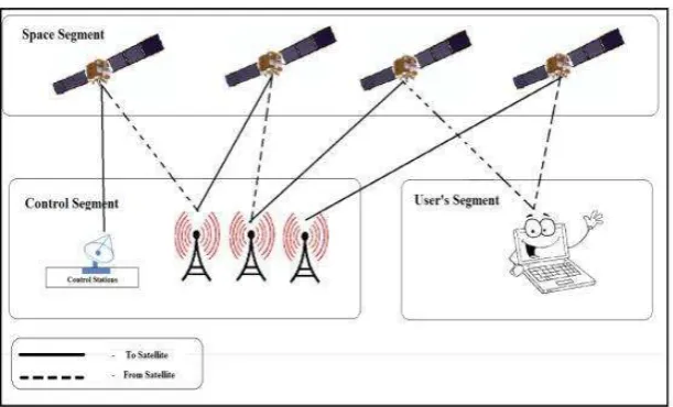
or more GPS satellites. The different segments of the GPS are Space segment, Control
segment and User segments.
The previous work is about Single point positioning, which is used in the determination of the
coordinates of a receiver with respect to the earth’s reference frame by intersection of the
signals from four or more satellites (also referred to as absolute positioning or simply point
positioning). In this paper, GPS single point positioning and velocity computation is carried
out from RINEX file under MATLAB Environment. Velocity computation is first
implemented and Detailed MATLAB codes are provided to perform more accurate results.
Factors that affect the accuracy of the computation, such as satellite selection, ionosphere
correction, satellite clock error calculation and correction, troposphere correction, and Earth
rotation correction, are all corresponding in order to obtain better position and velocity
results.
In the proposed work, the accurate position of the receiver is determined by finding the faulty
satellite and isolating those faulty satellites, so that the receiver can use the other satellite’s
signals. The accurate position is computed by using the “Newton-Raphson method” under the
MATLAB environment.
2 SYSTEM ARCHITECTURE
The current GPS consists of three major segments. These are the space segment (SS), a
control segment (CS), and a user segment (US). The U.S. Air Force develops, maintains and
Aruna et al. World Journal of Engineering Research and Technology
www.wjert.org 46
each GPS receiver uses these signals to calculate its three-dimensional location (latitude,
longitude, and altitude) and the current time. The Fig 1 represents the system architecture of
the Global Positioning System.
The control segment is composed of a master control station (MCS), an alternate master
control station, and a host of dedicated and shared ground antennas and monitor stations. The
user segment is composed of hundreds of thousands of U.S. and allied military users of the
secure GPS Precise Positioning Service, and tens of millions of civil, commercial, and
scientific users of the Standard Positioning Service. The space segments consist of space
vehicles.
Fig 1: System architecture of the Global Positioning System.
2.1 Space Segment
The space segment consists of 24 satellites, each in its own orbit 11000 nautical miles
(20,200 km) above the earth. The orbital period is one-half a sidereal day, i.e., 11 hours and
58 minutes so that the satellites pass over the same locations or almost the same locations
every day. The orbits are arranged so that at least six satellites are always within line of sight
from almost everywhere on Earth's surface. The space segment consists of solar panels,
external components and internal components.
2.2 Control Segment
The control segment is composed of a master control station (MCS), an alternate master
control station, and a host of dedicated and shared ground antennas and monitor stations. The
master control station (MCS) performs the primary control segment functions, providing
Aruna et al. World Journal of Engineering Research and Technology
www.wjert.org 47
they pass overhead and channel their observations back to the master control station. Ground
antennas are used to communicate with the GPS satellites for command and control purposes.
These antennas support S-band communications links that send/transmit navigation data
uploads and processor program loads and collect telemetry.
2.3 User Segment
The user segment is composed of hundreds of thousands of U.S. and allied military users of
the secure GPS Precise Positioning Service and tens of millions of civil, commercial, and
scientific users of the Standard Positioning Service. The user segment consists of receivers,
which you can hold in your hand or mounted in the vehicles. GPS receivers are composed of
an antenna, pre-amplifier, radio, microprocessor, control and display unit, data recording unit
and power supply.
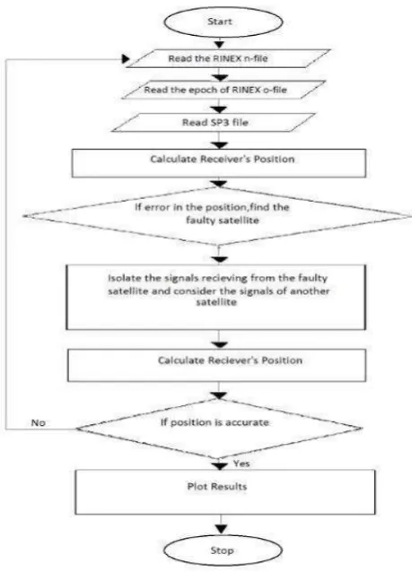
3 IMPLEMENTATION
Computation of the receiver’s ECEF position and velocity from its corresponding RINEX
observation and navigation files applying pseudo range and Doppler observations are
processed as shown in the Fig 2.
Aruna et al. World Journal of Engineering Research and Technology
www.wjert.org 48
3.1 Navigation Message File
The Navigation Message provides all the necessary information to allow the user to perform
the positioning service. It includes the Ephemeris parameters, needed to compute the satellite
coordinates with enough accuracy, the Time parameters and Clock Corrections, to compute
satellite clock offsets and time conversions, the Service Parameters with satellite health
information (used to identify the navigation data set), Ionospheric parameters model needed
for single frequency receivers, and the Almanacs. The ephemeris and clocks parameters are
usually updated every two hours, while the almanac is updated at least every six days.
3.2ObservationMessage File
Each Observation file basically contains the data from one site and one session. RINEX also
allows including observation data from more than one site subsequently occupied by a roving
receiver in rapid static or kinematic applications. The observation file consists of messages
that is sent to the receiver for every 30 seconds and which satellites are in line of sight at that
point of time. The message consists of pseudo ranges, Doppler values of the satellites which
are in the line of sight at that epoch of time.
3.3 Sp3 File Format
The format of the file is the satellite clock correction information which is computed
simultaneously with the orbits. The basic format is a position and clock record; a second,
optional, record contains velocities and clock rates-of-change. The Position Record Flag, P,
in line one indicates that no velocities are included. The Velocity Record Flag (V), in line one
indicates that at each epoch and for each satellite, a satellite velocity and clock rate-of-change
has been computed. The SP3 format has been designed such that satellites other than GPS
could be described as well.
3.4 Processing The Data Read
The algorithm by which, a GPS receiver computes the position of a satellite (x, y, z) in the
ECEF coordinate system from the orbital elements. So the data read are processed using the
equations of the ECEF coordinate system. Newton Raphson method, also called the Newton’s
method, is the fastest and simplest approach of all methods to find the real root of a nonlinear
Aruna et al. World Journal of Engineering Research and Technology
www.wjert.org 49
3.5 Computing The Receiver’s Position
In order to determine user position in three dimensions (x, y, z) and the offset t, Pseudo range
measurements are made to four satellites resulting in the system of equations. In order to
determine user position in three dimensions (x, y, z) and the offset t, pseudo range
measurements are made to four satellites resulting in the system of equations.
Where, xj, yj, and zj denote the jth satellite’s position in three dimensions and j = 1,2,3,4.
𝜌 represents the pseudoranges from the respective satellites
c represents the speed of light
tu represents the clock bias
xu, yu, zu is the initial user position.
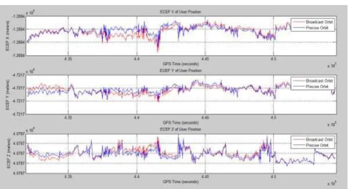
4 SCREENSHOTS AND RESULTS
4.1 Snapshots Without Faulty Satellites
The Fig 3 shows the 3-D user positions calculated from broadcast and precise orbits are very
close with each other, and it is hard to judge which one has better accuracy. The time range is
from 2008/11/07 00:00:00 UTC to 2008/11/07 06:14:30 UTC, or GPS time of 432000
seconds to 454470 seconds at GPS week of 1504. The total time duration is 22500 seconds at
30 seconds time interval. The ranges of the y-axis in the plot, indicates the position of the
satellite. The positive values in the y-axis indicates that the satellites is placed in front of the
receiver and negative value indicates that the satellite is behind the receiver.
Aruna et al. World Journal of Engineering Research and Technology
www.wjert.org 50
The Fig 4 is plotted by taking the approximate xyz position in the header of the observation
file as the reference user position; the relative user position to the reference can be found and
plotted. The x-axis which represents the GPS time from 43490seconds to 51890 seconds. The
y-axis which indicates the position of the satellite, where the positive values, which
corresponds to the receiver that is placed in front of the satellites and the negative values
which corresponds to the receiver that is placed behind the receiver.
Fig 4: Relative user position to the reference position.
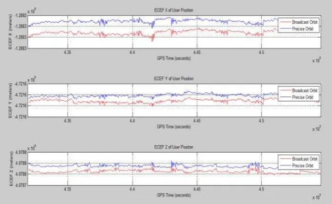
4.2Snapshots With Faulty Satellites
Fig 5 is similar to the Fig 3. This Fig shows, how the position is varied when the satellite has
an error of 100 meters.
Aruna et al. World Journal of Engineering Research and Technology
www.wjert.org 51
The Fig 6 is similar to the Fig 4. This Fig shows how the position is varied when the satellite
has an error of 100 meters.
Fig 6: Relative user position to the reference position with an error of 100 meters.
6 CONCLUSION AND FUTURE ENHANCEMENT
The technology of the Global Positioning System is used for computing the accurate position
of the receiver by detecting the faulty satellites and isolating those faulty satellites under the
MATLAB environment using “NEWTON RAPHSON’S METHOD”.
The project is developed to find the accurate position of the receiver and detecting the faulty
satellite and isolating those satellites. The future enhancement of this project can be
implemented on the Automation of GPS satellites which can also be enhanced by finding the
atmospheric delays which causes the deterioration of the receiver’s position. The goal is for
each update to occur automatically
REFERENCE
1. Elliot D. Kaplan, Christopher J. Hegarty, “Understanding GPS”, Principles and
Applications, Second Edition, Artech house, 2006.
2. Mohinder S. Grewal, Lawrence R. Weill, Angus P. Andrews “Global Positioning
Systems, Inertial navigation and Integration”, Second Edition, Wiley Interscience, 2007.
3. PratapMisra and Per Enge, “Global Positioning System: Signals, Measurements and
Performance”.
4. www.mathworks.com
5. Werner Gurtner, RINEX: The Receiver Independent Exchange Format Version 2.10, 10th
Aruna et al. World Journal of Engineering Research and Technology
www.wjert.org 52
6. Juliya Talaya, “robust GPS kinematic positioning for direct georeferencing”, institute
catografic de catunya.
7. Y. Gao and A.Wojciechowski, “high precision kinematic positioning using single dual
frequency GPS receiver”, the university of Calgary.
8. Wen Zhang, “GPS Single Point Positioning and Velocity Computation from RINEX File