TECHNICAL UNIVERSITY OF CLUJ-NAPOCA
ACTA TECHNICA NAPOCENSIS
Series: Applied Mathematics, Mechanics, and Engineering Vol. 61, Issue I, March, 2018
3R SERIAL ROBOT CONTROL BASED ON ARDUINO/GENUINO UNO, IN
JAVA, USING JDEVELOPER AND ARDULINK
Tiberiu Alexandru ANTAL
Abstract: The paper presents a scalable command strategy, in Java programming language, based on the Ardulink library, through strings, using JDeveloper IDE, of the servomotors from a 3R serial robot arm based on ARDUINO / GENUINO UNO microcontroller. The code gives the implementation in C under the Adruino IDE for reading and extracting the commands for servomotors, the serial communication parameters between the PC and the microcontroller, and the Java code for the serial transmission of the command line from the PC to the ARDUINO / GENUINO UNO microcontroller.
Key words: Java, JDeveloper, Arduino, Microcontroller, Ardulink.
1. INTRODUCTION
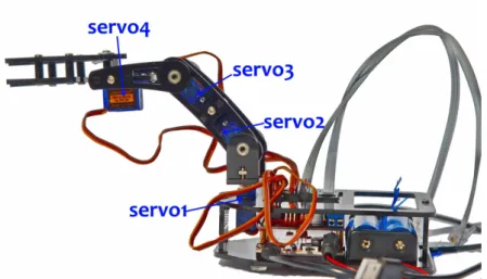
The paper gives a simple method of controlling a 3R serial robot that uses four servos (one used to drive the gripper) based on the Arduino/Genuino Uno microcontroller [1]. The serial robot is shown in Figure 1 and is based on the “DIY Control Robot Arm kit for
Arduino-Rollarm” found at
https://www.sunfounder.com/learn/category/DI
Y-Control-Robot-Arm-kit-for-Arduino-Rollarm.html.
The paper does not intend to discuss aspects related to the mechanical part and the mechanisms used in the construction of the robot. However, it must be emphasized that the robot arm is supported entirely by the servo1 (Figure 1) without any other machine parts that take up some of the load or stiffen the structure. This simplistic design will lead to a higher mechanical stress and a faster wear of the servomotor from the base compared to the other three servomotors.
2. ROBOT ARM HARDWARE
The Arduino/Genuino Uno boards are in fact the same board. Arduino Uno is the brand used to sell the board in the USA while Genuino Uno is the brand used outside the USA. Both
boards are programmed offline using the Arduino Desktop IDE [1], which must be installed before testing the code. The Uno is programmed using the Arduino Software (IDE), our Integrated Development Environment common to all our boards. The robot arm kit from Figure 1 is using the SunFounder Mars Board from Figure 2 which is an Arduiono Uno compatible board using the ATmega328P as processor and the same Optiboot bootloader as Uno (as a result it is programmable with Arduino IDE). The board is designed better than Arduino Uno as it’s using the more stable and reliable FTDI232R for USB-to-serial and Type-C USB Port (supports reversible plug orientation), adds a 5V power switch to control the board power (avoiding
frequent plugging) - see
Fig. 1. – The “DIY Control Robot Arm kit for Arduino-Rollarm”.
Fig. 2. – The SunFounder Mars Board.
Fig. 3. – The SunFounder Extension Board for Mars Board.
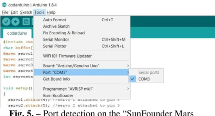
Fig. 5. – Port detection on the “SunFounder Mars Board” based on the Arduino drivers.
3. ROBOT ARM SOFTWARE
The following code uploaded from the Arduino IDE to the Mars Board over de USB Port will drive the servos of the robot. The code is written to work with four servos; however it can be easily scaled to a higher number of servos if it’s used on a robot with a different mechanical structure (with more servos). The Arduino programming language is C/C++ based and is extended through the use of libraries. The Servo standard library allows an Arduino board to control hobby servos (cheap servos under 100 USD). Standard servos allow the shaft to be positioned at various angles between 0° and 180°. However, hobby servos will be destroyed if are rotated to their extreme values, so a reasonable rotation domain would be from 20° to 160°. The Servo library supports
up to 12 motors on most Arduino boards. attached() function is used to connect the Servo object to a pin. write() function will set the angle of the shaft (in degrees), moving the shaft to that orientation. Aruino boards are using serial communication on pins TX/RX which are TTL logic levels (5V or 3.3V depending on the board and not +/- 12V). All Arduino boards have at least one serial port (also known as a UART or USART) called Serial. It communicates on digital pins 0 (RX) and 1 (TX) as well as with the computer via USB. The Serial port has functions that can be used to communicate over the port to some other serial device. Also, the Arduino IDE has a built-in serial monitor to communicate with an Arduino board (see Figure 6). This must have the same baud rate (9600 baud in this case) used in the call to
Serial.begin() function.
Serial.write() sends bytes to the serial port while Serial.print() sends ASCII characters so people can read easily. Serial.available() gets the number of bytes (characters) available for reading from the serial port and stored in the serial receive buffer (which holds 64 bytes).
#include <Servo.h>
char buffer[24]; //if more servos are used increase buffer size Servo servo1; // creare servo1 obiect
Servo servo2; // 2 Servo servo3; // 3 Servo servo4; // 4
void setup() {
servo1.attach(4); // servo 1 attached to pin 4 servo2.attach(5); // servo 2 attached to pin 5 servo3.attach(6); // servo3 > 6
servo4.attach(7); // servo4 > 7
Serial.begin(9600);
servo1.write(90); // servo1 > home servo2.write(90); // servo2 > home servo3.write(90); // servo3 > home servo4.write(150); // servo4 > closed
Serial.println("STARTING..."); }
{
if (Serial.available() > 0) { // check if data is sent int index = 0;
delay(500); // wait for the buffer to fill
int numChar = Serial.available(); // number of sent characters if (numChar > 24) {
numChar = 24; }
while (numChar--) {
// fill the buffer with the sent characters buffer[index++] = Serial.read();
}
splitString(buffer); // extract the angles for the servo1, …, 4 }
}
void splitString(char* data) { Serial.print("Data entered: "); Serial.println(data);
char* parameter;
parameter = strtok (data, " ,"); //String > token
while (parameter != NULL) { // if it’s not end of string then setServo(parameter); // run setServo
parameter = strtok (NULL, " ,"); }
// Clear the string and the serial buffer for (int x = 0; x < 24; x++) {
buffer[x] = '\0'; }
Serial.flush(); }
//print() and println() are for the Serial Monitor Window void setServo(char* data) {
//identify the servo by: q1,q2,q3 sau q4
if (((data[0] == 'Q') || (data[0] == 'q')) && ((data[1] == '1'))) { int val = strtol(data + 2, NULL, 10); // String to long integer val = constrain(val, 0, 180); // limit values
servo1.write(val);
Serial.print("Servo1 = "); Serial.println(val);
}
if (((data[0] == 'Q') || (data[0] == 'q')) && ((data[1] == '2'))) { int val = strtol(data + 2, NULL, 10);
val = constrain(val, 0, 180); servo2.write(val);
Serial.print("Servo2 = "); Serial.println(val);
}
if (((data[0] == 'Q') || (data[0] == 'q')) && ((data[1] == '3'))) { int val = strtol(data + 2, NULL, 10);
val = constrain(val, 0, 180); servo3.write(val);
Serial.print("Servo3 = "); Serial.println(val);
}
if (((data[0] == 'Q') || (data[0] == 'q')) && ((data[1] == '4'))) { int val = strtol(data + 2, NULL, 10);
val = constrain(val, 40, 150); servo4.write(val);
Serial.print("Servo4 = "); Serial.println(val);
The structure of an Arduino application is organized in two sections, the setup() and the loop() functions. The setup() function is used for initializations and is called only once when the code starts. In this example it is used to associate the servos to the de pins of the Mars Board through the Extension Board. Then, the serial communication speed is set to 9600 baud and the initial positions for the servos are set. The loop() function is executed repeatedly in order obtain an active control, through the program, over the devices connected to the Arduino Board. As shown in Figure 5 the code is able to drive a single servo ore more by handling the content of a single string. The string may have at most 24 characters and contains a list of qxyyy elements. Where x is and integer between [1,4] and yyy integer between [20,160]. q1100 will drive the q1 servo to an angle of 100°, while q3120,q4150 will drive q3 servo to 120° and q4 servo to 150°.
Fig. 6. – Arduino IDE built-in serial monitor window.
4. SOME WORDS ON THE SERVOS
A servo is a small DC motor with a potentiometer and a control circuit. The motor is attached by gears to the control wheel. As the motor rotates, the potentiometer's resistance changes and the control circuit can precisely regulate how much rotation there is and in which direction.
Servos are controlled by sending an electrical pulse of variable width, or pulse width modulation (PWM), through the control wire. There is a minimum pulse width, a maximum pulse width, and a repetition rate. A servomotor can usually only turn 90° in either direction for a total of 180° movement.
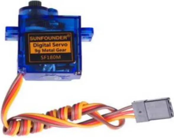
The SunFounder servos should have been as those presented in the Users Manual (see Figure 8), that is Digital Servo 9g Metal Gear SF180M. However, as shown in Figure 9, all servos are of type 9g SF180. This means that the gear part is made of plastic and not metal. All four servos are 9g that is they have 9 grams and they can rotate 180°. The connector for this type of servo is shown in Figure 6.
Fig. 7. – Connector pinout for 9g SF180 servos.
Due to the poor mechanical design, servo1 holds the full weight of the robotic arm. This mass will produce inertial forces when the arm moves. One way of dealing with this is the following code that will lead to a low acceleration of the arm when servo1 is moving the rest of the arm. M1 variable is of type int. val is the angle position to which we want to move the servo. The for cycles are moving with a 1 degree increment step the servo to the desired angle. By breaking a large angle variation in small and constant angle variations we obtain lower inertial forces. This way the movements won’t be sudden and the servo1 will be protected against high inertial forces.
M1 = servo1.read(); if ((val - M1) >= 0) {
for (; M1 <= val; M1++) {
servo1.write(M1); delay(50);
} } else {
for (; M1 > val; M1--) {
servo1.write(M1); delay(50);
} }
4. USING JAVA TO SEND STRINGS
TO THE MARS BOAD
help of Ardulink library [1]-[3]. The typical code for this must containg the following lines:
import org.zu.ardulink.Link; …
Link link = Link.getDefaultInstance(); …
link.writeSerial("q450");
If the USB port communication is initialized properly in Java via Ardulink the last line sends q450 string over the USB to the microcontroller (move servo q4 in 50° angle). The control of the robot servomotors through strings is essential in the situation of implementing client-server systems [4] for remote access to the robot via the Internet as strings can transferred and inspected easily over the network.
Fig. 8. – SunFounder servos according the User Manual.
If changes are required to the code due to a robot with different mechanical structure no modification at the Java code level is required. However, the code uploaded to the Arduino
board must be changed to work with less or more servos. This only implies to change the buffer size and to add or remove the proper ‘q’-lines to the setServo() function.
Fig. 9. – Real SunFounder servos from the package.
REFERENCES
[1] ANTAL, Tiberiu Alexandru. Arduino Leonardo
programming under Windows, in Java, from JDeveloper using Ardulink. ACTA TECHNICA NAPOCENSIS - Series: APPLIED
MATHEMATICS, MECHANICS, and
ENGINEERING, Nr. 60, Vol. 1, 2017, p.7-2, ISSN 1221-5872.
[2] ANTAL, T. A., Elemente de Java cu Jdeveloper
- îndrumător de laborator, Editura UTPRES, 2013, p.150, ISBN: 978-973-662-827-6.
[3] ANTAL, T. A., Java - Iniţiere - îndrumător de
laborator, Editura UTPRES, 2013, p. 246, ISBN: 978-973-662-832-0.
[4] ANTAL, Tiberiu Alexandru, CHELARU,
Julieta Daniela. A multithreaded java
client-server model for robot interaction. ACTA TECHNICA NAPOCENSIS - Series: APPLIED
MATHEMATICS, MECHANICS, and
ENGINEERING, Nr. 60, Vol. 3, 2017, p.7-2, ISSN 1221-5872.
CONTROLUL UNUI ROBOT SERIAL 3R BAZAT PE ARDUINO / GENUINO UNO, ÎN JAVA, DIN MEDIUL JDEVELOPER ŞI CU BIBLIOTECA ARDULINK.
Rezumat: Lucrarea prezintă o strategie scalabilă de comandă, din Java cu biblioteca Ardulink, prin şiruri de caractere, utilizând mediul JDeveloper, a unor servomotoare dintr-un robot serial 3R cu placă ARDUINO/GENUINO UNO. Codul dă implementarea în C sub mediul Adruino a citirii şi a extragerii comenzilor pentru servomotoare, parametrii comunicaţiei seriale între PC şi microcontroler şi codul Java pentru transmiterea serială a şirului de comandă de la PC la microcontrolerul ARDUINO/GENUINO UNO.