UDC [629.4.015:625.032.434]:531.3
O. H. REIDEMEISTER
1, V. O. KALASHNYK
2, O. A. SHYKUNOV
3*1Dep. «Cars and Cars Facilities», Dnipropetrovsk National University of Railway Transport named after Academician V. Lazaryan, Lazaryan St., 2, Dnipro, Ukraine, 49010, tel. +38 (056) 373 15 04, e-mail [email protected], ORCID 0000-0001-7490-7180
2Dep. «Cars and Cars Facilities», Dnipropetrovsk National University of Railway Transport named after Academician V. La-zaryan, Lazaryan St., 2, Dnipro, Ukraine, 49010, tel. +38 (056) 793 19 16, e-mail [email protected],
ORCID 0000-0002-8073-4631
3*Dep. «Cars and Cars Facilities», Dnipropetrovsk National University of Railway Transport named after Academician V. La-zaryan, Lazaryan St., 2, Dnipro, Ukraine, 49010, tel. +38 (056) 373 15 04, e-mail [email protected],
ORCID 0000-0002-8256-2634
METHOD OF CONSTRUCTING THE DYNAMIC MODEL OF
MOVEMENT OF THE MULTI-MASS SYSTEM
Purpose. The scientific work is intended to develop a methodology for describing the structure of the railway vehicles (they are considered as a system of rigid bodies connected by rigid, elastic and dissipative elements), which would allow us to obtain the equations of motion in an easily algorithmized way. Methodology. When constructing the model, authors tend to ensure that its structure reflects the structure of the mechanical system, that is, parts of the model must correspond to parts of the car. In this case, the model takes the form of a hierarchically organized graph whose vertices correspond to the bodies, attachment points of the connecting elements and to the connecting ele-ments themselves, and the edges describe the sets of processes that are related to the incident vertexes. As a rule, these are movements and forces: for the edge between the body and the attachment point they are generalized movements of the body and the general forces acting on it; for the edge between the attachment point and the con-necting element - the movements of the point and the forces arising in the element. To each vertex there corresponds a group of equations describing the motion of the system. The nature of the equations depends on the type of the vertex. For the body it is the equations of body motion; for the point - the expressions for the point displacements through generalized displacements of the body and generalized forces acting on the body, through the forces arising in the connecting element; for the connecting element - the expression for the forces arising in it through the defor-mation of the element. The graph can be regarded as oriented. The direction of the edge is chosen in such a way that for each vertex the values on the right-hand side of the vertex-associated equation would correspond to the incoming edge, and in the left-hand side - to the outgoing edge. Findings. A technique for constructing a dynamic model of oscillations of railway vehicles as a system of rigid bodies is developed on the basis of their description using hier-archically organized graphs. The technique was tested to construct a model of spatial oscillations of a 4-axle freight car with an axial load of 25 tons in Simulink package. Originality. For the first time, a technique has been developed for describing the structure of a railway vehicle using a hierarchical graph, which makes it possible to obtain equations of motion in an easily algorithmized manner. Practical value. The proposed methodological approach will allow, after creating a library of bodies and connecting elements, to significantly reduce the time spent on modeling the oscillations of different vehicles.
Keywords: oscillation model; railway vehicle; multi-mass system; graph
Introduction
At present, the approach to constructing models of car oscillations is well known and tested for as-sessing the car running qualities and dynamic load-ing of elements [12]. The car is considered as a set of solid bodies [1], connected by rigid, elastic, vis-cous, dissipative elements [10, 11, 13]. As a rule, the angles of rotation are considered small values, after which the compilation of the equations of
motion becomes a routine procedure, which it is advisable to deliver into charge of the computer.
two packages implement the language of the de-scription of dynamical systems Modelica [9]) and so on.
Purpose
To develop a methodology for describing the structure of the railway vehicles (they are con-sidered as a system of rigid bodies connected by rigid, elastic and dissipative elements), which would allow us to obtain the equations of motion in an easily algorithmized way.
Methodology
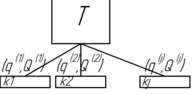
When building a model, we strive to ensure that its structure reflects the structure of the mechanical system (car), that is, parts of the model must cor-respond to parts of the car. In this case, the model takes the form of a hierarchically organized graph whose vertices correspond to the bodies and con-necting elements, and the edges describe the sets of processes that that are related to the incident to edge vertices [7]. An example of the general struc-ture of the model is shown in Figure 1.
Fig. 1. Car body: a – vertex representing, b – its internal structure. Pt1 and Pt2 are attachment points of pairs «Centre
plate - Centre pad»
As a rule, a set of generalized displacements and corresponding generalized forces correspond to the edge.
For the edge, causality conditions can be de-fined (for example, if the force is considered as a function of displacements) or not (forces and dis-placements are related by implicit relations). The difference between the two types of edges is not fundamental and, if desired, one can write down
the formal rules for determining the causality rela-tion.
To describe the model-building rules, we use the inductive approach and consider the basic types of subsystems and the corresponding equations. In doing so, we will try to match the set of equations to the node, and the set of variables to the edge.
Fig. 2. Fragment of «Bogie» subsystem
Figure 2 shows a fragment of the «Bogie»
sub-system, in which the bolster NB is connected to the solebars BR1, BR2 with the spring suspension unit
RP1, RP2. The motion of such a subsystem is
de-scribed by the equations that can be conveniently divided into the following groups:
1) Equations of motion of bodies;
2) Equations expressing the movement of the attachment points of the connecting elements through the movements of the bodies;
3) Equation of the relationship between the de-formation of the connecting element and the force that arises in it.
The last group of equations refers to the con-necting elements, the first two to the bodies. In view of the fact that the parameters of the equa-tions of the first two groups are different, it is ad-visable to equip each body with an internal struc-ture, as shown in Fig. 3, using the example of bol-ster.
The inner vertex «Body» corresponds to the
body motion equations. Internal vertices RP1, RP2,
PP, SK1, SK2 - to the attachment points of corre-sponding connecting elements: spring suspension, pair «Centre plate - Centre pad», side bearing. These classes of vertices (for the body, for attach-ment points of the connecting eleattach-ment and for the connecting element itself) are the basic ones for building the car model. We will dwell in detail on each of them.
The vertex representing the motion equations of the body, whose principal central axes of inertia are parallel to the coordinate axes, is shown in Fig. 4.
This vertex can be incident with several edges, each of which is associated with a set of gene-ralized displacements q( )j and generalized forces
( )j
Q . The edges connect the vertex «Body» with
the vertex «Point».
The physical meaning of the processes q( )j –is the generalized displacements of the body.
The vectors Q( )j correspond to generalized
forces acting on the body at the j-th point. The
body motion equation includes the sums of the components of these vectors, and the motion equa-tions themselves take the form:
2 2 2 2 2 2 2 2 2 2 2 2 , , , , , ' j j j j x j y j z d x m X dt d y m Y dt d z m Z dt d I dt d I dt d I dt
(1)where m – body mass, , , Ix Iy Iz – main central moments of inertia.
Variables corresponding to displacements are called variables of the potential type, and processes corresponding to the forces are variables of the current type. These names refer to Kirchhoff's laws
for electrical circuits and to the fact that the movements in the edges incident to one vertex are equated to each other, and the forces are added to-gether.
Fig. 4. Vertex «Body motion equations»
The vertex representing the «Point» (Figure 5)
is responsible for transforming the displacements and forces acting on the body (superscript «0») into the displacements of the point and the force applied to it (superscript «1»). The parameters of the vertex are the coordinates of the point
, ,
p p p
x y z in the coordinate system, whose origin
is in the center of gravity of the body. At small angles of rotation, the expressions that determines the relationship between the values q(0), Q(0) and
(1), (1)
q Q take the form:
1 0 0
1 0 0
1 0 0
1 0 1 0 1 0 0 1 0 1 0 1 0 1 0 1 0 1 0 0 , 0 , , 0 p p p p p p
x x z y
y y z x
y x z z X X Y Y Z Z 1 1 1 0 . 0 p p p p p p X z y
z x Y
y x Z
Fig. 5. Vertex «Point»
The «Connecting element» connects the
«Points» of two «Bodies», Figure 6.
Fig. 6. Vertex «Connecting element»
The deformation of the connecting element is the difference
(1) (0)
.
q q q
(3)
The force Q, arising in the connecting element
depends on the deformation q. The expression
for the force depends on the type of the connecting element. For example, for a linear spring of rigidity
C, operating in a vertical direction 0,
, 0.
X Y Z C z
(4)
It is convenient to assume that the force Q acts
on the Body-0 from the side of the Body-1. In this
case Q(0) Q
,
(1)Q Q
.
By combining the described types of vertices, it is possible to present in a compact and visual form a model of car oscillations, suitable for direct for-mation of the motion equations.
Let us consider the implementation of the de-scribed approach for building a model in the Simu-link package. In this case, the body, point and con-necting element are conveniently represented as subsystems. As an example, Figure 7 shows the Simulink scheme for the subsystem «Bolster».
Fig. 7. Subsystem «Bolster» in Simulink model A non-trivial matter is the question of compar-ing each edge with the direction of signal propaga-tion, which is chosen so that for explicit expression of some values through other the argument is the input, and the function is the output.
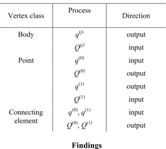
Having examined the expression (2), we see that the directions for displacements and the direc-tions for forces in one edge are opposite to each other. The direction of propagation for different signals is given in Table 1.
Table 1
Directions of signal propagation
Vertex class Process Direction
q(j) output
Body
Q(j) input
q(0) input
Q(0) output
q(1) output
Point
Q(1) input
q(0), q(1) input Connecting
element Q(0), Q(1) output
Findings
The use of the proposed method resulted in cre-ation of a freight car model, which consists of a body and two bogies. The bogies were considered as a construction consisting of the following sub-system-elements [2, 3]:
wheel sets with box; – solebars;
– springs of the central spring unit (each two-row spring separately);
– friction vibration dampers; – axle-box suspension; – centre pad;
– side bearing.
Each of these subsystems is independent and can be replaced with the condition of preserving the geometric parameters of the connection points of the element. This feature of the model is con-venient to use for changing the parameters in order to select their optimal values.
The bodies, with the exception of bolsters and bogie solebars, have 6 degrees of freedom; the angles of rotation are small. To better estimate the dynamic loading of the bogie cast parts, the de-tailed models of spring suspension (up to individ-ual springs and friction wedges, which are consi-dered as separate bodies of the system) and axle box were developed.
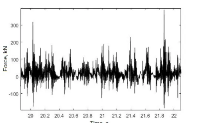
The model will be used to evaluate the dynamic loading of bogie elements of the car with an axial load of 25 tons [8], in order to clarify the loads arising during operation [4, 5, 14]. Vertical forces acting in the axle box when the car moves along a straight section of the track at 120 km/h speed are shown in Figure 8.
Originality and practical value
For the first time, a methodical approach to creating dynamic models of railway vehicles based on their description using hierarchically organized graphs was proposed.
Fig. 8. Vertical forces in the axle box of gondola car with axle load of 25 tons, speed of 120 km/h This methodological approach will allow, after creating a library of bodies and connecting ele-ments, to significantly reduce the time spent on modeling the oscillations of different vehicles.
Conclusions
A technique has been developed for describing the structure of a railway vehicle using a hierarchi-cal graph, which makes it possible to obtain equa-tions of motion in an easily algorithmized manner. The vehicle is a system of rigid bodies connected by rigid, elastic and dissipative elements. The technique was tested to construct a model of spatial oscillations of a 4-axle freight car in the Simulink package. Directions of further development: crea-tion of the library of bodies and connecting ele-ments, detailed presentation of the geometry of track, the models of track superstructure and wheel-rail interaction.
LIST OF REFERENCE LINKS
1. Виттенбург, Й. Динамикасистемтвердыхтел / Й. Виттенбург. – Москва : Мир, 1980. – 294 с.
2. Динамическиекачествагрузовыхвагонов, имеющихтележкисдиагональнымисвязями / Е. П. Блохин,
К. Т. Алпысбаев, Р. Б. Грановский [идр.] // Вісн. Східноукр. нац. ун-туім. ВолодимираДаля. – 2012. –
№ 5, ч. 1. – С. 12–16.
3. Определение допускаемыхскоростейдвижениягрузовых вагонов пожелезнодорожнымпутям колеи
1520 мм / В. Д. Данович, В. В. Рыбкин, С. В. Мямлин, А. Г. Рейдемейстер, А. П. Трякин, Н. В. Халипо
-ва // Вісн. Дніпропетр. нац. ун-ту залізн. трансп. ім. акад. В. Лазаряна. – Дніпропетровськ, 2003. –
Вип. 2. – С. 77–86.
4. Определениепараметровпространственногонагружениялитыхдеталейтележки 18-9855 припроведе
-ниистендовыхиспытаний / Д. В. Шевченко, Т. С. Куклин, А. М. Орлова [идр.] // Техникажелезных
дорог. – 2016. – № 1 (33). – С. 68–74.
5. Рейдемейстер, А. Г. Способыувеличенияпрочностибоковыхрамтрехэлементныхтележек / А. Г. Рей
-демейстер, А. А. Шикунов // Наука та прогрес транспорту. – 2015. – № 5 (59). – С. 141–149.
6. Черных, И. В. Simulink: Инструмент моделирования динамических систем [Electronic resource] /
И. В. Черных. – Available at: http://matlab.exponenta.ru/simulink/book1/index.php. – Title from the screen. –
Accessed : 31.08.2017.
7. Borutzky, W. Bond graph methodology: development and analysis of multidisciplinary dynamic system models / W. Borutzky. – Sankt Augustin : Springer Science & Business Media, 2009. – 662 p.
8. Bubnov, V. M. Dynamic performance of freight cars on bogies model 18-1711 / V. M. Bubnov, S. V. Myamlin, N. B. Mankevych // Наука та прогрес транспорту. – 2013. – № 4 (46). – С. 118–126. doi: 10.15802/stp2013/16616.
9. Fritzson, P. Introduction to modeling and simulation of technical and physical systems with Modelica / P. Fritzson. – Hoboken : John Wiley & Sons, 2011. – 211 p.
10. Handbook of railway vehicle dynamics / Edited by S. Iwnicki. – Boca Raton : CRC press, 2006. – 526 p. 11. Knothe, K. Rail vehicle dynamics / K. Knothe, S. Stichel. – Cham : Springer, 2017. – 321 p.
12. Shabana, A. A. Dynamics of multibody systems / A. A. Shabana. – Cambridge : Cambridge university press, 2013. – 374 p.
13. Shabana, A. A. Railroad vehicle dynamics: a computational approach / A. A. Shabana, K. E. Zaazaa, H. Sugiyama. – Boca Raton : CRC press, 2007. – 343 p.
14. Shykunov, O. A. Three-Element Bogie Side Frame Strength / O. A. Shykunov // Наукатапрогрестранспор
-ту. – 2017. – № 1 (67). – С. 183–193. doi: 10.15802/stp2017/92535.
О
.
Г
.
РЕЙДЕМЕЙСТЕР
1,
В
.
О
.
КАЛАШНИК
2,
О
.
А
.
ШИКУНОВ
3*1Каф. «Вагонитавагоннегосподарство», Дніпропетровськійнаціональнийуніверситетзалізничного
транспортуіменіакадемікаВ. Лазаряна, вул. Лазаряна, 2, Дніпро, Україна, 49010, тел. +38 (056) 373 15 04,
ел. пошта [email protected], ORCID 0000-0001-7490-7180
2Каф. «Вагонитавагоннегосподарство», Дніпропетровськійнаціональнийуніверситетзалізничного
транспортуіменіакадемікаВ. Лазаряна, вул. Лазаряна, 2, Дніпро, Україна, 49010, тел. +38 (056) 793 19 16,
ел. пошта [email protected], ORCID 0000-0002-8073-4631
3*Каф. «Вагонитавагоннегосподарство», Дніпропетровськійнаціональнийуніверситетзалізничного
транспортуіменіакадемікаВ. Лазаряна, вул. Лазаряна, 2, Дніпро, Україна, 49010, тел. +38 (056) 373 15 04,
ел. пошта [email protected], ORCID 0000-0002-8256-2634
МЕТОДИКА
ПОБУДОВИ
ДИНАМІЧНОЇ
МОДЕЛІ
РУХУ
БАГАТОМАСОВИХ
СИСТЕМ
Мета. Унауковійроботінеобхіднорозробитиметодикуописуструктуризалізничнихекіпажів (розгля
-даютьсяяк систематвердихтіл, з’єднаних жорсткими, пружними та дисипативнимиелементами), якадо
-зволилаботримати рівнянняруху способом, що легкоалгоритмізується. Методика. При побудовімоделі
авторипрагнутьдотого, щобїїструктуравідображаластруктурумеханічноїсистеми, тобточастинимоделі
повиннівідповідати частинамвагона. При цьому модельнабуває форму ієрархічно організованого графа,
вершиниякоговідповідаютьтілам, точкамкріпленняз’єднувальнихелементівтасамимз’єднувальнимеле
-ментам, а ребра описують сукупності процесів, які мають відношення до інцидентнихребру вершин. Як
правило, цепереміщеннятасили: дляребраміжтіломіточкоюкріплення – узагальненіпереміщеннятілата
діючінаньогоузагальненісили; дляребраміжточкоюкріпленняйз’єднувальнимелементом – переміщен
-няточкиісили, щовиникаютьвелементі. Кожнійвершинівідповідаєгрупарівнянь, щоописуютьрухсис
-теми. Характеррівняньзалежитьвідтипувершини. Длятіла – рівняннярухутіла; дляточки – виразипере
-міщеньточкичерезузагальненіпереміщеннятілайузагальненихсил, щодіютьнатіло, черезсили, щови
-никаютьуз’єднувальномуелементі; дляз’єднувальногоелемента – виразидлясил, щовиникаютьвньому,
черездеформаціїелемента. Графможерозглядатисяякорієнтований. Напрямокребраобираютьтакимчи
-ном, щобдлякожноївершинивеличини, щостоятьуправійчастинізіставленихвершинірівнянь, відповіда
-лиребру, щовходить, авлівій – виходить. Результати.Розробленометодикупобудовидинамічноїмоделі
коливаньзалізничнихекіпажівяксистемитвердихтілнаосновіїхописузадопомогоюієрархічноорганізо
-ванихграфів. Методикавипробуванадляпобудовимоделіпросторовихколивань 4-вісноговантажногова
описуструктури залізничного екіпажу задопомогоюієрархічного графа, яка дозволяє отримати рівняння
руху способом, що легко алгоритмізується. Практична значимість. Запропонований методичний підхід
дозволить, після створення бібліотеки тіл та з’єднувальних елементів, значно скоротити витрати часу на
моделюванняколиваньрізнихекіпажів.
Ключовіслова: модельколивань; залізничнийекіпаж; багатомасовасистема; граф
А
.
Г
.
РЕЙДЕМЕЙСТЕР
1,
В
.
А
.
КАЛАШНИК
2,
А
.
А
.
ШИКУНОВ
3*1Каф. «Вагоныивагонноехозяйство», Днепропетровскийнациональныйуниверситетжелезнодорожного
транспортаимениакадемикаВ. Лазаряна, ул. Лазаряна, 2, Днипро, Украина, 49010, тел. +38 (056) 373 15 04,
эл. почта [email protected], ORCID 0000-0001-7490-7180
2Каф. «Вагоныивагонноехозяйство», Днепропетровскийнациональныйуниверситетжелезнодорожного
транспортаимениакадемикаВ. Лазаряна, ул. Лазаряна, 2, Днипро, Украина, 49010, тел. +38 (056) 793 19 16,
эл. почта [email protected], ORCID 0000-0002-8073-4631
3*Каф. «Вагоныивагонноехозяйство», Днепропетровскийнациональныйуниверситетжелезнодорожного
транспортаимениакадемикаВ. Лазаряна, ул. Лазаряна, 2, Днипро, Украина, 49010, тел. +38 (056) 373 15 04,
эл. почта [email protected], ORCID 0000-0002-8256-2634
МЕТОДИКА
ПОСТРОЕНИЯ
ДИНАМИЧЕСКОЙ
МОДЕЛИ
ДВИЖЕНИЯ
МНОГОМАССОВОЙ
СИСТЕМЫ
Цель.Внаучнойработенеобходиморазработатьметодикуописанияструктурыжелезнодорожныхэки
-пажей (рассматриваются как система твердых тел, соединенных жесткими, упругими и диссипативными
элементами), которая позволила б получить уравнения движения легко алгоритмизируемым способом.
Методика.Припостроениимоделиавторыстремятсяктому, чтобыееструктураотражаластруктурумеха
-ническойсистемы, тоестьчастимоделидолжнысоответствоватьчастямвагона. Приэтоммодельприобре
-таетформуиерархическиорганизованного графа, вершиныкоторогосоответствуют телам, точкамкрепле
-ниясоединительныхэлементовисамимсоединительнымэлементам, аребраописываютсовокупностипро
-цессов, которыеимеютотношениекинцидентнымребрувершинам. Какправило, этоперемещенияисилы:
дляребрамеждутеломиточкойкрепления – обобщенныеперемещениятелаидействующиенанегообоб
-щенныесилы; дляребрамеждуточкойкрепленияисоединительнымэлементом – перемещенияточкииси
-лы, возникающие вэлементе. Каждой вершинесоответствует группауравнений, описывающих движение
системы. Характеруравнений зависитоттипавершины. Длятела – уравнениядвижениятела; для точки –
выраженияперемещений точкичерезобобщенные перемещениятела иобобщенных сил, действующихна
тело, черезсилы, возникающиевсоединительномэлементе; длясоединительногоэлемента – выражениядля
сил, возникающихвнем, через деформацииэлемента. Графможетрассматриваться какориентированный.
Направлениеребравыбираюттакимобразом, чтобыдлякаждойвершинывеличины, стоящиевправойчас
-ти сопоставленных вершине уравнений, соответствовали входящему ребру, а в левой – исходящему.
Результаты. Разработанаметодикапостроения динамическоймоделиколебанийжелезнодорожныхэкипа
-жейкаксистемытвердыхтелнаосновеихописанияспомощьюиерархическиорганизованныхграфов. Ме
-тодикаопробованадляпостроениямоделипространственныхколебаний 4-осногогрузовоговагонасосевой
нагрузкой 25 тсвпакете Simulink. Научнаяновизна.Впервыеразработана методикаописанияструктуры
железнодорожногоэкипажаспомощьюиерархическогографа, котораяпозволяетполучитьуравнениядви
-жения легко алгоритмизируемым способом. Практическая значимость. Предложенный методический
подходпозволит, после создания библиотеки телисоединительныхэлементов, значительносократить за
-тратывременинамоделированиеколебанийразличныхэкипажей.
Ключевыеслова: модельколебаний; железнодорожныйэкипаж; многомассоваясистема; граф
REFERENCES 1. Vittenburg, Y. (1980). Dinamika sistem tverdykh tel. Moscow: Mir.
3. Danovich, V. D., Rybkin, V. V., Myamlin, S. V., Reydemeyster, A. G., Tryakin, A. P., Khalipova, N. V. (2003). Determination of permissible speeds of freight cars on railroad tracks 1520 mm. Bulletin of Dnipropetrovsk National University of Railway Transport, 2, 77-86.
4. Shevchenko, D. V., Kuklin, T. S., Orlova, A. M., Savushkin, R. A., Dmitriev, S. V., & Belyankin, A. V. (2016). Opredeleniye parametrov prostranstvennogo nagruzheniya litykh detaley telezhki 18-9855 pri provedenii stendovykh ispytaniy. Railway Equipment Magazine, 1 (33), 68-74.
5. Reidemeister, O. H., & Shykunov, O. A. (2015). Strength increase methods of the side frame of the bogie in three-piece trucks. Science and Transport Progress, 5 (59), 141-149. doi:10.15802/stp2015/55351
6. Chernykh, I. V. (n.d.). Simulink: Instrument modelirovaniya dinamicheskikh system. MATLAB.Exponenta! Retrieved from http://matlab.exponenta.ru/simulink/book1/index.php
7. Borutzky, W. (2010). Bond graph methodology: development and analysis of multidisciplinary dynamic system models. Sankt Augustin: Springer Science & Business Media. doi:10.1007/978-1-84882-882-7
8. Bubnov, V. M., Myamlin, S. V., & Mankevych, N. B. (2013). Dynamic performance of freight cars on bogies model 18-1711. Science and Transport Progress, 4 (46), 118-126. doi:10.15802/stp2013/16616
9. Fritzson, P. (2011). Introduction to modeling and simulation of technical and physical systems with Modelica. Hoboken: John Wiley & Sons. doi:10.1002/9781118094259
10. Iwnicki, S. (Ed.). (2006). Handbook of railway vehicle dynamics. Boca Raton: CRC press.
11. Knothe, K., & Stichel, S. (2017). Rail vehicle dynamics. Cham: Springer. doi:10.1007/978-3-319-45376-7 12. Shabana, A. A. (2013). Dynamics of multibody systems. Cambridge: Cambridge university press.
13. Shabana, A. A., Zaazaa, K. E., & Sugiyama, H. (2007). Railroad vehicle dynamics: A computational approach. Boca Raton: CRC press.
14. Shykunov, O. A. (2017). Three-element bogie side frame strength. Science and Transport Progress, 1 (67), 183-193. doi:10.15802/stp2017/92535
Prof. S. V. Myamlin, D. Sc. (Tech.), (Ukraine); PhD Tech., Senior Research Associate T. V. Sheleiko (Ukraine) recommended this article to be published