Proceedings of the
Seventh International Workshop on
Graph Transformation and Visual Modeling Techniques
(GT-VMT 2008)
Visual Design and Reasoning
with the Use of Hypergraph Transformations
Ewa Grabska, Gra˙zyna ´Slusarczyk and Truong Lan Le
15 pages
Guest Editors: Claudia Ermel, Reiko Heckel, Juan de Lara
Managing Editors: Tiziana Margaria, Julia Padberg, Gabriele Taentzer
Visual Design and Reasoning
with the Use of Hypergraph Transformations
Ewa Grabska1, Gra˙zyna ´Slusarczyk2and Truong Lan Le3
1[email protected] 2[email protected]
The Faculty of Physics, Astronomy and Applied Computer Science Jagiellonian University, Krak´ow, Poland
Polish-Japanese Institute of Information Technology, Warszawa, Poland
Abstract: This paper deals with visual design and reasoning. A visual language with its internal representation in the form of attributed hierarchical hypergraphs is discussed. Hypergraph attributes allow for defining and analysing constraints im-posed by design knowledge. Operations on hypergraphs which reflect modifications of design diagrams are also presented. The approach is illustrated by examples of designing floor-layouts.
Keywords: visual design, graph transformations, hypergraphs, knowledge-based reasoning
1
Introduction
This paper describes a knowledge-based decision support design system where designs are con-figurations of visual elements. Both partial and complete design solutions are represented in the form of diagrams forming a specific visual language, called the layout language. The syntactic knowledge of this language is defined by means of attributed hierarchical hypergraphs.
The proposed approach constitutes an attempt to solve the problem of transforming the visual design knowledge into a computer internal representation for a system which is to support the designer in the early stage of the design process [GGLŁ ´S, G ´SG]. The compatibility between the proposed visual language and the internal representation that serves as a base for reasoning about designs is discussed.
In our approach each diagram drawn by the designer is represented in the form of an attributed hierarchical hypergraph. Hyperedges of hypergraphs represent both diagram components and the multi-argument relations among them. Hierarchical hyperedges correspond to groups of diagram components. Hypergraphs nested in these hyperedges correspond to subcomponents of the diagram parts. Hierarchical hypergraphs not only reflect the top-down way of designing but also enable the designer to consider the project on the specified level of detail and allow one to express relations between components on different hierarchy levels. Attributes assigned to hyperedges encode the semantic design knowledge.
to divide a chosen area of the layout into smaller parts the operation called hyperedge develop-ment [G ´SG], is used. A reverse operation, called hyperedge suppression, which allows one to redesign the chosen area, is defined in this paper.
The paper strongly recommends the designer to interact with the computer system on the level of a visual language. The knowledge stored in the attributed hypergraph representation of dia-grams allows the system to reason about layouts and to support the designer by suggesting further steps and prevent him/her from creating designs not compatible with the specified constraints or criteria. The approach is illustrated by examples of designing floor-layouts.
2
Related work
This paper deals with supporting conceptual design phase by a knowledge-based system. Nowa-days detailed design and design documentation phases are usually well supported in CAD tools such as ArchiCAD, Architectural Desktop and AllPlan, etc. [Szu]. Although there are many computational tools for describing, editing, analyzing, and evaluating design projects [Min], there still exists lack of consistency between knowledge visualization of the given domain (ar-chitecture, construction, machine building) and its internal representation in a computer program. This is one of the reasons that the initial design phase, called conceptual design, is the least sup-ported one.
Our approach proposes a visual representation of designs together with their internal represen-tation. Such a method allows one to equip the design editor with intelligent assistants support-ing creative design by reasonsupport-ing about the project features and suggestsupport-ing design modifications. When developing a visual language the role of sketches in the conceptual design phase was taken into consideration [Gol]. Therefore elements of our language contain general ideas about design objects and are not treated as completed design components used in design visualizations in all CAD tools.
Graphs and hierarchical structures are used quite frequently in knowledge-based design tools [SWZ]. Our approach is based on a formal model of hierarchical hypergraphs introduced in [DHP] and extended in [´Slu]. This type of hypergraphs enables us to express multi-argument relations between elements on different hierarchy levels, which is essential in design. Our hyper-graphs can be treated also as an extension of hyperhyper-graphs used by [Min], which are too restrictive in expressing relations.
3
Design Diagrams and Attributed Hierarchical Hypergraphs
In this section we present an example of a visual language, called a layout language, which en-ables the designer to create and edit floor-layouts. A vocabulary of this language is composed of shapes corresponding to components like rooms, walls, doors, windows, while the rules specify-ing possible arrangements of these components constitute its syntactic knowledge. Elements of the layout language are diagrams seen as simplified architectural drawings.
(b) (a)
Figure 1: a) An architectural drawing, b) a design diagram
location of polygons is determined by design criteria. Lines with small squares on them represent the accessibility relation among components, while continuous lines shared by polygons denote the adjacency relations between them. The accessibility relation between two areas is specified when the existence of a wall with doors, a fragment of a wall or lack of a wall are planned in a floor-layout design. When a wall dividing two areas is not planned, the location of a line repre-senting the accessibility relation is determined by the specified sizes of the areas. The sides of each polygon are ordered clock-wise starting from the top left-most one. In a design diagram only qualitative coordinates are used i.e., only relations among graphical elements (walls) are essential.
Each design diagram has its internal representation in the form of an attributed hierarchical layout hypergraph. Such a hypergraph contains two types of hyperedges, which can represent components and spatial relations on different levels of details. Hyperedges of the first type are non-directed and correspond to layout components. Hyperedges of the second type represent relations among components and can be either directed or non-directed in the case of symmetrical relations. Considering floor-layout design only spatial relations which are by nature symmetrical (accessibility and adjacency) are taken into account.
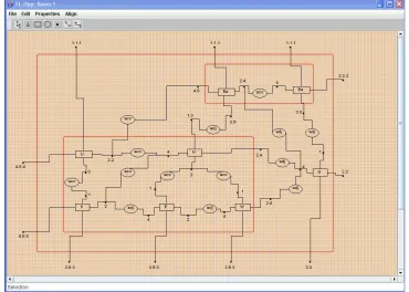
An example of the internal representation of the diagram presented in Figure 1(b) is shown in Figure2. This hypergraph is composed of eleven component hyperedges, three of which are hierarchical ones, and fourteen relational hyperedges, where half of them represent the acces-sibility relation and the other half the adjacency relation. The relational hyperedge connecting node 2.2 of the hyperedge labelled Lr and node 4.6 of the hyperedge labelled Be is one of the hyperedges expressing relations between components nested in different parent hyperedges.
Figure 2: A hierarchical layout hypergraph corresponding a design diagram from Figure 1(b)
windows or doors) of elements corresponding to hyperedges and nodes.
The proposed hierarchical layout hypergraph constitutes a modification of hypergraphs pre-sented in [Min, ´Slu] and is defined as follows.
Let[i]denote the interval[1,i]of natural numbers (with[0] = /0) and letΣ=ΣE∪ΣV, where ΣE∩ΣV = /0, be a fixed alphabet of hyperedge and node labels, respectively. Let At be a set of
hyperedge and node attributes.
Definition 1 An attributed hierarchical layout hypergraph overΣ=ΣE∪ΣV and At is a system G= (EG,VG,sG,tG,lbG,attG,extG,chG),where :
1. EG=EGC∪EGR is a nonempty finite set of hyperedges, where elements of EGC represent
object components, while elements of EGRrepresent relations and EGC∩EGR= /0,
2. VGis a nonempty finite set of nodes,
3. sG: EG→(VG)∗and tG: EG→(VG)∗are two mappings assigning to hyperedges sequences
of source and target nodes respectively, in such a way that∀e∈ECGsG(e) =tG(e),
4. lbG=lbEG∪lbVG, where:
• lbEG : EG→ΣE is a hyperedge labelling function, such that ΣE =ΣCE∪ΣRE ∧ΣCE∩ ΣR
• lbVG: VG→ΣV is a node labelling function,
5. attG=attEG∪attVG, where:
• attEG: EG→P(At)is a hyperedge attributing function,
• attVG: VG→P(At)is a node attributing function,
6. extG:[n]→VGis a mapping specifying a sequence of hypergraph external nodes,
7. chG: EGC→P(A) is a child nesting function, where A=EG∪VG is called a set of
hy-pergraph atoms, and such that one atom cannot be nested in two different hyperedges, a hyperedge cannot be its own child, source and target nodes of a nested hyperedge e are nested in the same hyperedge as e.
Hyperedges of the layout hypergraph are labelled by names of components or relations. A se-quence of source and target nodes is assigned to each hyperedge and express potential connec-tions to other hyperedges. Moreover, for each hierarchical hypergraph a sequence of external nodes is determined. A child nesting function ensures that one atom cannot be embedded in two different hyperedges. It also guarantees that there are no ancestor-descendant cycles in a hypergraph, which means that a hyperedge cannot be its own child.
4
Operations on Hierarchical Layout Hypergraphs
It is known that a design process cannot be a priori defined in an algorithmic way. During a design process the designer often modifies a design diagram and/or changes design goals before he gets a plausible solution. To reflect these changes in our internal representation of a visual language we equip the proposed system with operations acting on hierarchical layout hypergraphs. They allow the system to create and modify hypergraphs representing structures of objects being designed.
The hyperedge development operation, which enables to represent a model structure on a more detailed level, was defined in [G ´SG]. It takes two hierarchical hypergraphs as arguments and nests in a hyperedge corresponding to an object element in the first hypergraph the second hypergraph representing the components of this element and relations among them. The nodes connected to a developed hyperedge are substituted by the corresponding external nodes of the child hypergraph.
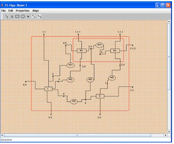
Now we define in a formal way an operation called a hyperedge suppression, which is a reverse to a development operation. It is useful when the designer wants to redesign the chosen area. Then he/she has to remove the existing area division before dividing it in a different way. A suppression operation takes as an argument a hierarchical layout hypergraph and removes the nested contents of one of its earlier developed component hyperedges.
Let us consider Figure2and Figure3. Figure3presents the result of applying a suppression operation consisting in removing a hypergraph H nested in the hyperedgeee labelled L
corre-sponding to the living area (Figure2).
Let SG(e)and TG(e)denote sets of all nodes specified by sequences of source and target nodes
Definition 2 Let G be an attributed hierarchical layout hypergraph over Σ=ΣE∪ΣV and At,
andee∈ECGbe a component hyperedge of G such that there exists a hierarchical layout hypergraph
H overΣand At, and ch+G(ee) =EH∪VH, where ch+Gdenotes the transitive closure of chG.
Let EX THdenote a set of external nodes of H, V denote a finite set of nodes such that V∩VG=/0, E denote a set of all relational hyperedges of EGR\EHR and connected with nodes of EX TH, and E′denote a finite set of relational hyperedges such that E′∩EG=/0.
Let a function substr(string1,string2)return a substring of string1without the prefix string2.
The hyperedge suppression operation is defined by three functions:
1. a suppression function sup : EX TH→V defined in such a way that
∀v,w∈EX THsubstr(lbG(v),|lbH(v)|) =substr(lbG(w),|lbH(w)|)⇒sup(v) =sup(w),
is a surjection which determines the correspondence between a set of new nodes and ex-ternal nodes of H assigning one node to all nodes with labels which differ only by a prefix number.
2. a suppression labelling function lbsup: V →ΣV defined in such a way that
∀v∈V lbsup(v) =substr(lbG(w),|lbH(w)|), where w∈sup
−1(v),
is a mapping assigning to new nodes labels obtained by removing prefixes from labels of the corresponding external nodes of H.
3. a suppression embedding function embsup : E→E′ is a surjection which determines the
correspondence between a set of new relational hyperedges and relational hyperedges con-nected with external nodes of H.
The result of the hyperedge suppression operation is an attributed hierarchical layout hypergraph
e
G= (EGe,VGe,sGe,tGe,lbGe,attGe,extGe,chGe)overΣand At, where:
1. EGe= (EG\EH\E)∪E′,
2. VGe= (VG\VH)∪V ,
3. sGe: EGe→(VGe)∗and tGe: EGe→(VGe)∗are defined in such a way that:
• sGe(ee) =tGe(ee)⊆Ve∗, whereVe=SG(ee)∪V ,
• ∀e∈EG\EH\E\ {ee}sGe(e) =sG(e)∧tGe(e) =tG(e),
• ∀e∈E′sGe(e) = f(e)∧tGe(e) = f(e)where f : E′→(VGe)∗,
4. lbGe=lbEGe∪lbVGe, where:
• ∀e∈EG\EH\E lbGe(e) =lbG(e),
• ∀e2∈E′lbGe(e2) =lbG(e1), where e1∈emb −1 sup(e2),
• ∀v∈VG\VHlbGe(v) =lbG(v), • ∀v∈V lbGe(v) =lbsup(v),
5. attGe=attEGe∪attVGe, where:
• ∀e2∈E′attGe(e2) =attG(e1), where e1∈emb −1 sup(e2),
• ∀v∈VG\VHattGe(v) =attG(v),
• ∀v∈V attGe(v) =h(v), where h : V →P(At),
6. extGe:[en]→VGe×ΣV.
7. ∀e∈EGC\ {ee}chGe(e) =chG(e)∧ch+Ge(ee) = /0.
As the result of the hyperedge suppression operation the hypergraph H is removed from the component hyperedgee of G. The external nodes of H are substituted by the correspondinge
nodes of V which become new source nodes of the hyperedgee. The correspondence amonge
nodes is established by a suppression function sup on the basis of the node labels. The source nodes ofee have the same labels as before a development operation onee.
The suppression embedding function replaces the relational hyperedges connected to the ex-ternal nodes of H by new relational hyperedges connecting nodes of G to source nodes ofee. The
way of replacing each hyperedge by the corresponding set of new hyperedges is specified on the basis of design constraints.
Let us come back to the example of the suppression operation removing a hypergraph H nested in the hyperedgeee labelled L corresponding to the living area (Figure2 and Figure3). Node replacing specified by the function sup determines six new nodes (a set V ) corresponding to ten external nodes of the nested hypergraph. The labels of new nodes are obtained by removing prefixes coming from the corresponding external nodes of the removed hypergraph. For example two nodes with labels 2.4 representing east walls of the hall and toilet, respectively, are merged into one node with label 4 representing the north side of the area L, while three nodes labelled 3.5.3 are merged into one node labelled 5.3 and representing the south wall of the living area. The four relational hyperedges which were connected with nodes 2.2, 1.3, 2.4 and 2.4 (E = 2.2,1.3,2.4,2.4) are replaced by three new relational hyperedges of E
′ connected with nodes
2, 3 and 4 of the hyperedge labelled L according to the suppression embedding function. As the result of this suppression operation a hierarchical layout hypergraph shown in Figure 3 is obtained.
5
Visual reasoning
Visual languages play a similar role in design as design sketches as they enable to follow changes made in design diagrams. Nowadays computer systems with visual languages should be equipped with intelligent tools capable of assisting the user in a computational process. Such tools ought to be able to reason on the basis of the internal representations of visual language elements.
The presented system is able to reason about the diagram being designed and suggest the de-signer modifications which are needed and warn him/her against creating solutions not compati-ble with the specified constraints. To this end the system is equipped with a set Sr of predicates of the form r : P(H)×K → {T RU E,FALSE}, whereH denotes a family of attributed
Figure 3: The hierarchical layout hypergraph obtained by removing a hypergraph from the hy-peredge representing the sleeping area
tests whether the predefined criteria are satisfied for the presently generated hierarchical layout hypergraph.
Design knowledge is divided into syntactic knowledge Ks and interpretation knowledge Ki
[CRRBG]. The predicates of Sr are divided into syntactic predicates (St) based on syntactic knowledge and semantic ones (Sm) based on interpretation knowledge. Each predicate of St has a specified subhypergraph which is searched for in a layout hypergraph created so far. After each hypergraph development operation, which nests a hypergraph in a hyperedge, for each component hyperedge of a nested hypergraph a predicate r1∈St, which tests the accessibility
of the corresponding room or area, is activated. This predicate searches for a subhypergraph shown in Figure4(a), where Lab denotes a label of a component hyperedge. For example in a hypergraph nested in a hyperedge representing the whole apartment (Figure2) and presented in Figure8(b) for both component hyperedges labelled S and L one such subhypergraph is found, while for a hyperedge labelled G representing a garage a searched subhypergraph is not found. The designer is notified that there is no inside connection of a garage and it is accessible only from the outside of the house.
Dr acc K Lab
(b)
acc
(a)
Figure 4: a) A subhypergraph of a predicate r1, b) a subhypergraph of a predicate r2
Figure 5: Testing the direct accessibility between two chosen areas
a living area and a bedroom, which is shown in Figure5, both areas are marked using white squares.
Predicates belonging to a set Sm enable the system to perform semantic analysis of the gen-erated hypergraph. The semantic reasoning about a design diagram is performed on the basis of identifiers and present values of attributes assigned to hypergraph atoms. To each component hy-peredge the attribute area, whose value specifies the area of the corresponding space, is assigned. To relational hyperedges labelled acc the attribute type is assigned. Its value specifies the way in which the adjacent spaces are accessible (by the door, by lack of a fragment or a whole wall between them). To hypergraph nodes the attributes position and window number are assigned. They specify the location of the walls and the numbers of windows which the walls contain.
D E S I G N E R Diagram Editor Constraint Editor Graphical object Editor DESIGNER Hypergraph Generator Hypergraph visualizaton control Constraint Module Constraint verificator Constraint solver
Figure 6: A system architecture
of a letter L, while for the hyperedges of the second type, a semantic predicate r5 tests if the corresponding areas have the shape of a letter T . Predicate r4 searches for two pairs of nodes, each of them representing two non-collinear and parallel walls, and such that walls represented by these pairs are not perpendicular (hyperedges S and L in Figure8(b)). Predicate r5 searches for three nodes representing three parallel walls with the same orientation and such that at most two of them are collinear, one node representing a wall which is parallel to the mentioned three walls but has the opposite orientation. Two remaining pairs of nodes should represent parallel and non-collinear walls with opposite orientations.
6
Implementation
In this section a structure of the system HGSDR (Hypergraph Generator Supporting Design and Reasoning) is presented. The system allows the designer to edit diagrams and automatically applies operations on hierarchical layout hypergraphs being internal representations of diagrams. It also gives the possibility to define constraints and reason about design diagrams.
The system is written in Java and contains four modules (Figure6): a graphical interface for editing objects and constraints, a constraint module for reasoning about diagrams, a hierarchical layout hypergraph generator and a control module for hypergraph visualization. The graphical interface enables the designer to construct diagrams of visual elements directly accessible in the editor or taken from a library of objects defined by the user or an external library of domain-oriented objects. A set of visual primitives, which are directly accessible, contains points, line segments, polygons and arcs. Texts can be used to describe primitives. The graphical interface allows the designer to interactively create and edit both objects, their attributes and constraints concerning these attributes.
Figure 7: Choosing diagram areas whose corresponding hyperedges should be visible
solves constraint equations defined on hypergraph attributes and sends messages to the designer. It prompts the designer which diagram transformations are needed. When the designer changes values of attributes, which are connected by specified constraints (like distance or location), the system can force the appropriate constraints to be satisfied by changing sizes of some objets and drawing a new diagram again.
The hierarchical layout hypergraph generator automatically creates hypergraphs, where hy-peredges correspond to diagram components and relations between them. The control module for hierarchical hypergraph visualization verifies and updates an existing hierarchy and enables to group components of the same hierarchy level and show relations between these groups and other components being on different levels of the hypergraph hierarchy. Navigation across dif-ferent layers of a hypergraph is possible due to an auxiliary tree of hierarchy. Using this tree the designer chooses hyperedges which should be visualized and decides if their contents should be visible. In Figure7the rooms nested in the sleeping area are not chosen in the tree of hierarchy and therefore the contents of the hyperedge corresponding to the sleeping area is not visible in the hypergraph.
7
Case Study
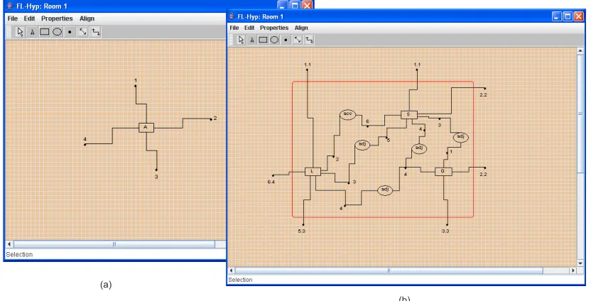
(b) (a)
Figure 8: a) A component hyperedge representing the whole area of the apartment, b) a hierar-chical layout hypergraph obtained as a result of a hyperedge development operation
drawn by the designer represents the area of the whole apartment. The initial hypergraph repre-senting this diagram, that is automatically generated (Figure8(a)), is composed of one hyperedge connected with four external nodes representing sides of the area and placed in the diagram ac-cording to the geographical location of the sides they correspond to.
In the next step, the designer divides the whole apartment area into three parts representing a living area, sleeping area and a garage, respectively (Figure 9(a)). As a consequence, the hyperedge development operation on the layout hypergraph is invoked automatically. As the result of this operation the layout hypergraph representing the three areas and adjacency rela-tions between them is nested in the hyperedge representing the whole apartment. The obtained hierarchical layout hypergraph is shown in Figure8(b).
The four external nodes of the hyperedge shown in Figure8(a) are replaced by seven external nodes of the nested layout hypergraph in respect to their geographical orientations. The labels of the external nodes of the layout hypergraph nested in the hyperedge representing the apartment are concatenated with labels denoting the number of the parent hyperedge node they replaced. The node number 1 of the apartment is replaced by nodes representing north sides of the living area (L) and the sleeping area (S). Both new nodes are labelled 1.1, where the first part of this label denotes that they correspond to first sides of areas L and S, while the second part of the label is inherited from the node which they replaced. The node number 2 is replaced by node 2 of the sleeping area and node number 2 of the garage, where both of them represent east sides of the diagram and are labelled 2.2. The node number 3 is replaced by node number 3 of the garage (labelled 3.3) and node number 5 of the living area (labelled 5.3). The node number 4 of the apartment is replaced by the node number 6 of the living area (labelled 6.4).
(a)
(b)
Figure 9: a) Three areas of the apartment, b) the apartment with the divided sleeping area
adjacent to each other (Figure9(b)). This modification of the design diagram results in nesting the layout hypergraph representing these rooms and adjacency between them in the hyperedge labelled S representing the sleeping area. As the result of applying the hyperedge development operation the hierarchical layout hypergraph presented in Figure3is obtained.
Six external nodes of the hyperedge labelled S are replaced by seven corresponding external nodes of the nested hypergraph. The labels of these seven nodes are concatenated with labels de-noting numbers of the parent hyperedge nodes they replaced. For example, the node labelled 1.1 of the sleeping area is replaced by nodes representing north walls of the bedroom (Be) and bath-room (Ba) (nodes 1.1.1 and 1.1.1, respectively).The relational hyperedges which were connected with nodes 3, 4, 5 and 6 of the hyperedge labelled S are replaced by new relational hyperedges connected with nodes 3.3, 2.4, 3.5, and 4.6 of the nested hypergraph, respectively.
(b) (a)
W Lr
K
Figure 10: a) A redesigned diagram, b) a hierarchical layout hypergraph corresponding to it
another one with node 2.4 of the hyperedge labelled W (Figure2).
If the designer is not satisfied with the layout of the living area and decides to change it, then she/he removes the division of this area and goes back to the diagram shown in Figure9(b). As a consequence, the hyperedge suppression operation on the layout hypergraph is invoked auto-matically. As the result of this operation the hierarchical layout hypergraph shown in Figure3is obtained. The nodes which were divided by the development operation are merged again. Node replacing is specified in such a way that the merged nodes are given the same labels which they had before the development operation was used.
In the next step the living area is divided into four spaces corresponding to a living-room, kitchen, entrance and a toilet. The design diagram obtained as a result of a new division of L and the corresponding hierarchical layout hypergraph are presented in Figure10(a) and Figure10(b).
8
Conclusions
This paper is the next step in developing a visual language to support innovative design. In our approach the designer’s modifications of diagrams are reflected by operations performed on their hypergraph representations. The way of reasoning about design diagrams on the syntactic and semantic level, based on knowledge stored in attributed hierarchical layout hypergraphs, that enables the system to suggest the designer modifications of created solutions, is also described.
Bibliography
[CRRBG] R. D. Coyne, M. A. Rosenman, A. D. Radford, M. Balachandran, J. S. Gero.
Knowledge-based Design System. Addison-Wesley, Sydney, 1990.
[DHP] F. Drewes, B. Hoffmann, D. Plump. Hierarchical Graph Transformation. In J. Tu-ryn (ed.), Proc. of FOSSACS 2000, LNCS 1784, pp. 98–113, Springer, 2000.
[Gol] G. Goldschmidt. The Dialetic of Sketching. Creativity Research Journal, 4, 1991.
[GGLŁ ´S] E. Grabska, K. Grzesiak-Kope´c, J. Lembas, A. Łachwa, G. ´Slusarczyk. Hyper-graphs in Diagrammatic Design. In K. Wojciechowski et al. (eds.), Proc. of the
International Conference ICCVG 2004. Computer Vision and Graphics, pp. 111–
117, Springer, 2006.
[G ´SG] E. Grabska, G. ´Slusarczyk, M. Glogaza. Design Description Hypergraph
Lan-guage. In M. Kurzy´nski et al. (eds.), Computer Recognition Systems 2, Advances
in Soft Computing 45, pp. 763–770, Springer, 2007.
[GLŁ ´SG] E. Grabska, J. Lembas, A. Łachwa, G. ´Slusarczyk, K. Grzesiak-Kope´c. Hier-archical Layout Hypergraph Operations and Diagrammatic Reasoning. Machine
Graphic & Vision, in print, 2007.
[Min] M. Minas. Concepts and Realization of a Diagram Editor Generator Based on Hypergraph Transformation. Science of Computer Programming 44, pp. 157–180, 2002.
[Pal] W. Palacz. Algebraic Hierarchical Graph Transformation. Journal of Computer
and System Sciences 68, pp. 497–520, 2004.
[SWZ] A. Sch¨urr, A. Winter, A. Z¨undorf. Graph grammar engineering with PROGRES. In W. Sch¨afer, P. Botella (eds.), Proc. of the 5th European Software Engineering
Conference (ESEC95), LNCS 989, pp. 219–234, Springer-Verlag, Berlin, 1995.
[Szu] J. Szuba. Graphs and Graph Transformations in Design in Engineering. PhD the-sis, PAS, Warszawa, 2005.
[ ´Slu] G. ´Slusarczyk. Hierarchical Hypergraph Transformations in Engineering Design,