i
A SYSTEM ARCHITECTURE FOR PHASED DEVELOPMENT OF REMOTE SUAS OPERATION
A Thesis presented to
the Faculty of California Polytechnic State University, San Luis Obispo
In Partial Fulfillment
of the Requirements for the Degree Master of Science in Aerospace Engineering
ii © 2020 Eric Ashley
iii
COMMITTEE MEMBERSHIP
TITLE: A System Architecture for Phased Development of Remote sUAS Operation
AUTHOR: Eric Ashley
DATE SUBMITTED: March 2020
COMMITTEE CHAIR: Aaron Drake, Ph.D.
Professor of Aerospace Engineering
COMMITTEE MEMBER: Kira Abercromby, Ph.D.
Professor of Aerospace Engineering
COMMITTEE MEMBER: Arnold Deffo, Ph.D.
Assistant Professor of Aerospace Engineering
COMMITTEE MEMBER: Paulo Iscold, Ph.D.
iv ABSTRACT
A System Architecture for Phased Development of Remote sUAS Operation Eric Ashley
v
ACKNOWLEDGMENTS
vi
TABLE OF CONTENTS
Page
LIST OF TABLES ... ix
LIST OF FIGURES ... x
NOMENCLATURE ... xi
1. INTRODUCTION ... 1
1.1 Problem Statement ... 1
1.2 Background ... 2
1.3 Project Definition ... 5
2. METHODOLOGY ... 8
2.1 Introduction to System Architecture Development ... 8
2.2 Operational Concept ... 9
2.3 Functional Architecture ... 10
2.4 Physical Architecture ... 12
2.5 Operational Architecture ... 12
2.6 Specific Design Methods ... 14
2.7 Summary of System Architecture Development ... 14
3. SYSTEM ARCHITECTURE ... 16
3.1 System Architecture Design ... 16
3.2 Operational Concept ... 16
3.2.1 Scenarios/System Use ... 17
3.2.2 External System Diagrams ... 20
3.2.3 Objective Hierarchy ... 24
vii
3.2.5 Operational Concept Summary ... 38
3.3 Functional Architecture ... 38
3.3.1 Functional Hierarchy ... 39
3.3.2 Input and Output Relationships ... 41
3.3.3 Stakeholder Input ... 42
3.4 Physical Architecture ... 42
3.5 Operational Architecture ... 44
3.5.1 Physical Component Functions... 44
3.5.2 Functional Flow, Activation, and Control ... 45
3.6 Summary of System Architecture Development ... 47
4. PHASE I PROTOTYPE DEVELOPMENT ... 48
4.1 Requirements ... 49
4.1.1 Functional Requirements ... 50
4.1.2 Interface Requirements ... 56
4.1.3 Non-Functional Requirements ... 57
4.1.4 Enabling Requirements ... 60
4.1.5 Constraints ... 63
4.2 Component Selection ... 64
4.2.1 Processor ... 65
4.2.2 Data Acquisition ... 68
4.2.3 Sensors ... 70
4.2.4 Communications ... 72
4.2.5 Power ... 73
4.3 Phase I Prototype Build ... 73
viii
5. RESULTS ... 77
5.1 Testing ... 77
5.1.1 Component Testing ... 77
5.1.2 Ground Testing ... 77
5.1.3 Flight Testing ... 78
5.1.4 Testing Results ... 78
5.2 System Validation ... 85
5.2.1 Functional Requirements ... 85
5.2.2 Interface Requirements ... 87
5.2.3 Non-Functional Requirements ... 88
5.2.4 Enabling Requirements ... 90
5.2.5 Constraints ... 91
5.3 Results Summary... 92
6. CONCLUSION ... 94
ix
LIST OF TABLES
Table Page
1. An example of a functional activation and control table ... 13
2. Categories for employment, life, and validation and testing scenarios ... 18
3. Operational concept for the system ... 19
4. High-level operational concept for the system ... 20
5. Functional input/output relationships ... 41
6. The functional flow, activation, and control for the system ... 46
7. The processing unit options for the system ... 66
8. The data acquisition options for the system ... 69
9. Components selected to interface with the Raspberry Pi ... 71
10. Functional Requirements Validation ... 87
11. Interface Requirements Validation ... 88
12. Non-Functional Requirements Validation ... 89
13. Enabling Requirements Validation ... 90
x
LIST OF FIGURES
Figure Page
1. Full project development process ... 6
2. Simple external system diagram of the system ... 21
3. External system diagram of Phase III data control loop ... 23
4. External system diagram of the Phase I and II data control loop ... 24
5. The physical architecture of the system... 43
6. Functions performed by physical elements of the system ... 45
7. Wiring diagram of the system... 74
8. The packaged system for the AFL's Nova and Vapor 55 vehicles ... 75
9. The packaged system modified to fly on for the AFL's Nova sUAS ... 76
10. The path of the Nova vehicle during the second flight test ... 79
11. Acceleration in the thrust direction of the Nova during flight test ... 80
12. The altitude of the Nova vehicle during flight test ... 81
13. Data packets collected onboard and received at the GCS by distance... 82
14. Data packets collected onboard and received at the GCS by altitude ... 82
xi
NOMENCLATURE
AFL Autonomous Flight Laboratory
AGL Above ground level
C2 System Command and control system
Cal Poly California Polytechnic State University, San Luis Obispo
CG Center of gravity
CPU Central processing unit CSV Comma separated values DAQ Data acquisition unit
DOF Degree of freedom
EFR Educational Flight Range EMI Electromagnetic interference FAA Federal Aviation Administration GCS Ground control station
GNSS Global Navigation Satellite System GPIO General purpose input/output GPS Global Positioning System HAT Hardware attached on top I2C Inter-Integrated Circuit
IEEE Institute of Electrical and Electronics Engineers IMU Inertial measurement unit
MCU Microcontroller
MTOW Maximum takeoff weight NAS National airspace system SBC Single board computer
1
1. INTRODUCTION
1.1 Problem Statement
Many researchers utilize unmanned aircraft systems (UAS) as tools for collecting data and performing tasks. Specifically, small unmanned aircraft systems (sUAS) have become a significant contributor for wildlife monitoring, agriculture, and healthcare delivery. However, operational limitations imposed by the Federal Aviation Administration (FAA) inhibit these end users from harnessing the full potential of sUAS. In some cases, sUAS are not as practical or cost effective as a traditional aircraft to the end user (Christie, 241).
Researchers continue to utilize sUAS but cite three fundamental impediments to improved effectiveness. The FAA regulations do not allow for significant operational variation because of the restrictions requiring the vehicle to remain within line of sight of the operator and under 400 feet above the ground. Furthermore, these restrictions do not encourage the production of vehicles with improved capabilities because their utilization is not allowed in the current national airspace system (NAS). The regulations also impede the advancement of alternative mission types which may increase operational efficiency.
2
1.2 Background
The FAA defines sUAS as vehicles with a maximum takeoff weight (MTOW) under 55 pounds. The FAA's Part 107 Rules allow the operation of sUAS in the NAS, but restrict the operation to remain within line of sight of the operator, under 400 feet above ground level, and in designated airspace zones (Federal Aviation Administration, 1). Despite these rules, sUAS still find utility in certain applications as end users seek to find more effective methods for data collection and package delivery.
Increased effectiveness of sUAS across a range of wildlife and ecology monitoring tasks for sea lions, killer whales, and sea otters could change the way scientists collect ecological data. Data has been collected which directly compared the capability of these sUAS monitoring tasks with traditional methods. The conclusion of this research was that sUAS provide better image resolution and did not disturb the target animals as much as a traditional aircraft (Christie, 251). Furthermore, the ability of sUAS to successfully capture wildlife populations and count individuals rivals the capability of traditional methods (Linchant, 247).
high-3
resolution imagery from sUAS flying at low altitudes could also improve the understanding agriculturalists have of crops needs and reactions to specific management techniques (Hunt, 2).
sUAS have shown utility delivering healthcare products in areas where rapid transport of critical medical supplies can be challenging as well. Zipline, a company headquartered in San Francisco, partnered with the country of Rwanda to address the problem of supplying hospitals with the blood when traditional infrastructure is impassable. Zipline has been successfully delivering critical healthcare products using their sUAS network since October 2018. The Zipline distribution center can deliver life-saving blood to one of 21 hospitals in a 75-kilometer range using their sUAS platform. An operator at the distribution hub monitors all missions and can send commands to the vehicle if needed (Ackerman, 34). Other studies have focused on a similar concept by comparing two models for sUAS delivery systems against traditional methods. The models concluded that under some circumstances it was advantageous to send critical medical supplies by sUAS than traditional methods. For example, the delivery company DHL's Parcel sUAS transferred medicine between Bavarian Alpine villages in 8 minutes when a DHL Parcel van would have taken 30 minutes. The models support sUAS capability for a more timely, efficient, and economical healthcare delivery system (Scott, 3297).
4
have increased operational capability in the current NAS. However, there is widespread belief that the regulations will eventually change to allow for more capable vehicles employed with more sophisticated operational concepts such as a single operator in control of multiple vehicles and beyond line of sight control (Atkins, 11), (Trujillo, 936).
The future operational concept envisioned with the expansion of sUAS regulations in the NAS would allow for sUAS to fly autonomously beyond line of sight. This capability would significantly increase the utility of vehicles for some applications. As such, there has been considerable research focused on a future NAS where sUAS fly beyond line of sight of their operator. Safety measures are beginning to be analyzed at a modeling level which indicate there are effective collision avoidance strategies for sUAS flying in a congested NAS (Luxhøj, 933). Consideration has also been given to the implementation of an unmanned aircraft management system which would require sUAS to register flights to avoid airspace conflicts with other aircraft. Furthermore, the system could act as a form of air traffic monitoring resource for the remote operator and vehicle (Jiang, 124).
5
imperative that a human be ready to intervene during flight-critical decisions even if the complexity of that interaction is still unknown (Ruff, 6).
1.3 Project Definition
A plethora of research has been completed regarding the airspace systems and human control aspect of a sUAS, or multiple sUAS, flying beyond line of sight of an operator, but no literature was found for a system to test the operational concept. Due to this lack of research and need to understand the operational requirements in anticipation of sUAS integration with the NAS, the Autonomous Flight Laboratory (AFL) at California Polytechnic State University, San Luis Obispo (Cal Poly) has initiated a project for initial testing of such as system. The AFL is interested in validating the operational concept and identifying applications for which this operational concept is well-suited. The project for developing an initial system will be divided into three phases:
Phase I: Develop a prototype system for collecting flight data from a sUAS and sending
it to a remote operator at a ground station.
Phase II: Complete Phase I and provide the remote operator with control of a payload
onboard the sUAS.
Phase III: Complete Phase I, Phase II, and provide the remote operator with control of
the sUAS.
6
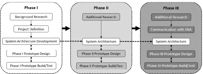
the modification of the FAA's Part 107 Rules or authorization for beyond line of sight testing via a certificate of authorization. A flow chart for the three-phase development of the project is shown in Figure 1. It illustrates the major steps for development of each phase. Phase I requires background research and development of a system architecture for the full system followed by a prototype build. Phase II builds on the research and system architecture developed in Phase I to enhance the prototype. Phase III builds on the Phase II work and, with FAA approval, develops a beyond line of sight sUAS control system.
Figure 1: Full project development process.
This project for the AFL is meant as a first research test article for beyond line of sight operational functionality. All the development is intended to function with vehicles owned by the laboratory, and not as a template for building a mission-specific sUAS control system.
This thesis will complete Phase I of the project with these specific objectives:
7
2. Design and build a prototype flight data collection system to work with the AFL’s Vapor and Nova sUAS.
3. Test the prototype to validate the system architecture design and prototype development.
8
2. METHODOLOGY
2.1 Introduction to System Architecture Development
The development of the system architecture was the most significant portion of the project because its scope included all three phases of the project. A successful system architecture should provide a framework which can be filled in using the specific requirements for a design. It should be able to accept design versions and iterations while ensuring the stakeholder needs.
To this end, the development of a system architecture can be approached many ways. There is no universal method for system architecture development. The result of the system architecture design is assessed by the success of the specific design built using the system architecture framework. Validating the development at the end inherently makes system architecture development an iterative process. As issues with the architecture are found during a specific design iteration, the architecture should be modified to accommodate the needs of the design and then reassessed. The notion which remained constant through the development of the system architecture was to focus on the elements fundamental to the system performing as desired by the system stakeholders.
9
Further guidance for development of the system requirements were provided by Lockheed Martin's report for an intelligent transportation system and IEEE's guide for developing system requirements (Martin, 12), (IEEE Computer Society, 11). These sources provided procedural, but no technical, insight for developing system requirements.
The system architecture development began by defining the operational concept of the system, using that operational concept to inform the design of the physical and functional architectures, and finally combining all the elements into a cohesive operational architecture. This general form was followed by Hayes and in this thesis, but the detailed processes for filling out the system framework were based on what fundamentally agreed with the development of this system architecture.
2.2 Operational Concept
The development of the operational concept is essentially envisioning the system in use for all scenarios. The scenarios are representative of the employment needs specified by the stakeholders. The scenarios should be exhaustive, including any foreseeable use case of the device and the non-operational, life scenarios where the system is utilized but not under normal use conditions. The rigorous characterization of scenarios should begin with the most simplistic scenarios, slowly becoming more complicated. As the system is imagined in increasingly more complicated scenarios, the needs of the stakeholders and systems become abundantly clear.
10
drawn out. The system will have some known inputs from the external context entities, perform some function using that information, and perform some output actions in response to the inputs. The precise function and method for perform the tasks are not described, but the connection between elements in the system with external elements provide insight into the interaction of the system with the world. These diagrams are called external system diagrams because they include the key interactions of the system with external systems and context entities.
The final consideration of the operational concept is to organize the objectives of the subsystems into a hierarchy. From the external system diagrams, the interactions between the system, subsystem, external systems, and context entities provide the basis for organizing the interactions. The order of the objective hierarchy will assist with specific design decisions because they list the objectives from the most to the least important. These objectives are not described fully, but rather a representation of the interactions and how they should be prioritized. Using the scenarios, external system diagrams, and objective hierarchy, the operational concept is a fully defined framework which will be a reference for defining elements of the functional and physical architectures.
2.3 Functional Architecture
11
The first step of the functional architecture is the organization of the system functions into a hierarchy. Through composition and decomposition methods, the system functions and sub-functions should be defined. The sub-functions can be identified from scenarios defined the operational concept, external system diagrams, or needs from the physical architecture under concurrent development.
Using the definitions of the functions, the direct relationships between the inputs and outputs of the systems, subsystems, and context entities are highlighted. Essentially, which interactions require which functions. Furthermore, the added detail will allow for sequencing the functions for these interactions. The methods for modeling these relationships can take the form of flow block diagrams or data flow diagrams.
During these processes, decisions about the system will need to be made which will require input from the stakeholders. The key takeaway from the stakeholder at this point should be for any glaring absence of necessary features. As with all the processes in the system architecture development the completion of the functional architecture may require multiple iterations.
A set of specifications describing the each of the system elements should be traced from the stakeholder needs drafted in the operational concept section. This process should verify that all the stakeholder needs are satisfied by an appropriate function. This check will also correlate with resources defined in the physical architecture during the development of the operational architecture.
12
the functional architecture is last because it can be difficult to consider failures so early on in development. Thus, it is often filled in more completely during the operational architecture phase. The consideration of potential failures and fault tolerances, additional input and output needs may be identified.
2.4 Physical Architecture
The physical architecture is developed concurrently with the functional architecture. It represents the resources which comprise the system and correspond to each of the functions defined in the functional architecture. The first step is to create a generic physical architecture based on the functions from the functional architecture. From there, more detail is added until the physical architecture fully compliments the operational architecture during iterative development. Multiple versions of the physical architecture should be completed in concurrence with the functional architecture to act as options during the development of the operational architecture.
In addition to describing the physical resources needed, the physical architecture indirectly defines the procedures needed by the system. The physical elements in the architecture act in specific ways which inform the procedures and controls of the system. These ideas can help inform changes or additions to the functional architecture as well as provide information for the operational architecture to be developed next.
2.5 Operational Architecture
13
this thesis were to apply functions to their specific physical resources and define the inputs and controls required for a specific functional output.
The first step for developing the operational architecture is to apply functions from the functional architecture to resources in the physical architecture. Thus, diagrams of the relationship between the physical and functional architectures are defined as a framework which can be filled in during the specific design.
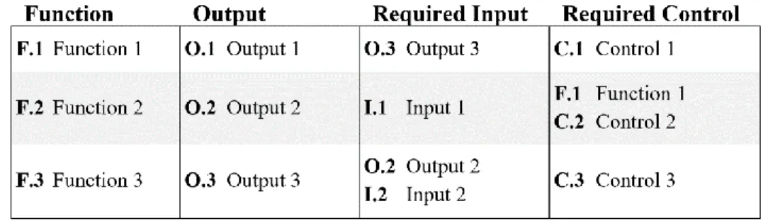
The second step is to understand the inputs, controls, and outputs for the various functions defined in the functional architecture. This occurs in a functional activation and control table such as the example in Table 1.
Table 1: An example of a functional activation and control table .
14
Once the analysis is complete the architecture is ready for use as a framework for specific design requirements.
2.6 Specific Design Methods
There are numerous techniques for systematically addressing preliminary and critical design. They use requirements as an input and apply creative solutions to reach a final output. However, for each design, a new design process must be started. To avoid the need to continuously redesign using the same requirements, a different approach was employed. The system engineering task was to develop the system architecture, then fill in the framework with design specifics. By utilizing this framework, much of the work for redesigning can be bypassed.
References for specific designs were scant, but a two were referenced for guiding the design decisions. One system utilized a microcontroller (MCU) (Brusov, 133) while the other was built around a single board computer (SBC) (Taha, 132). Both systems proved capable of collecting flight data on a sUAS.
2.7 Summary of System Architecture Development
15
16
3. SYSTEM ARCHITECTURE
3.1 System Architecture Design
The specific system architecture development for this thesis is described in the following section. The operational concept for the system was developed, then the functional and physical architectures were identified and refined, and finally the parts were combined into a cohesive framework called the operational architecture.
The operational architecture acts as the framework to be filled in during the prototype design phase. As design modifications are needed or requirements change, the architecture shall continue to serve as the framework which can support any updated designs. Thus, the process of defining the system architecture in the following section only needs to be completed once while allowing flexibility for the specific design and subsequent variants.
3.2 Operational Concept
17
3.2.1 Scenarios/System Use
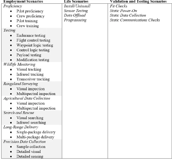
The operational and life scenarios of the system were determined to support the description of the operational concept. In this case, the system is a sub-system for a larger sUAS mission, so its functions do not change much between mission types. The system will be used for employment, life, and validation tasks as shown in Table 2. The scenarios listed under the categories are a comprehensive list of envisioned scenarios but is not exhaustive. Employment scenarios include the missions sUAS vehicles fitted with the system are anticipated to fly. Life scenarios include use of the system for anything which is not flight data collection. Finally, validation and testing scenarios include the use of the system to validate the design satisfies the requirements.
18
Table 2: Categories for employment, life, and validation and testing scenarios.
19
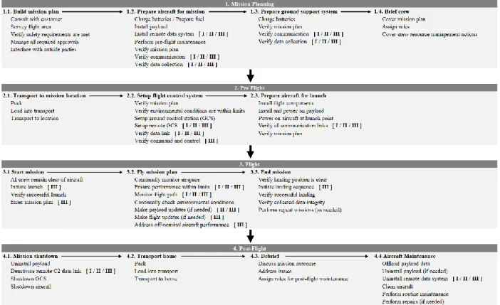
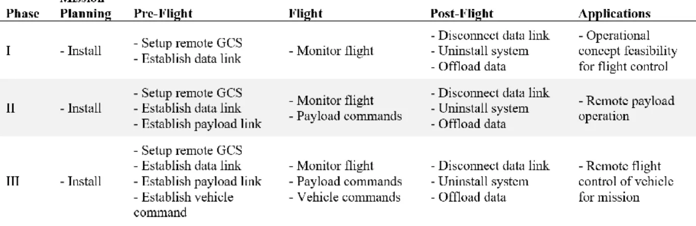
control the payload. Phase III required that the system collect and transmit flight data, control the payload, and provide control of the vehicle. With each phase the capability of the system became more advanced, and mission success became more reliant on the system. A simplified version of the mission concept highlighting the different phases can be found in Table 4.
Table 3: Operational concept for the system.
20
system will only be used to monitor flight status, whereas during Phases II and III the system will also be used by the remote pilot to send commands to either the payload or vehicle. The exact mechanism for these functions were not determined using the operational concept but need for that functionality was identified.
Table 4: High-level operational concept for the system.
The development of the mission operational concept was based on the structure for building missions by the AFL. This ensured all three phases of the system will integrate seamlessly with the procedures used by the AFL. However, for integration with another operational structure, some small tweaks may be required. The changes would likely be small, but worth investigating before attempting to use this operational concept as a model.
3.2.2 External System Diagrams
21
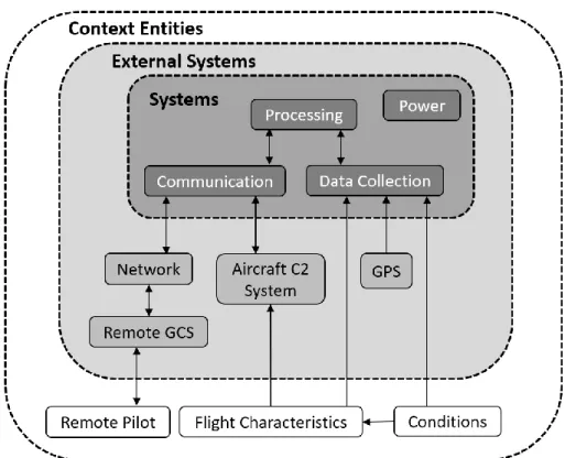
vehicle, global positioning system (GPS) infrastructure, and data link for communication with the remote ground station. The context entities included the flight characteristics of the vehicle, local weather, and the remote pilot input, when applicable in Phase III.
The simple external system diagram is a tool for understanding what the system will need to interact with, both functionally and physically. However, it describes those components at a high level as an introduction to the system in the context of the operational concept. The simple external system diagram is shown in Figure 2.
Figure 2: Simple external system diagram of the system.
22
communication sub-system connects to the external network which then connects with the remote ground control station. The communication system also connects with the vehicle command and control system to relay commands from the remote pilot during Phase III. The data collection sub-system connects with the GPS external system because it will collect GPS data. Furthermore, the data collection sub-system connects with the weather conditions and flight characteristics because the sensors in the system will collect data dependent on how the vehicle is flying. Internal to the system the processing sub-system links the data collection and communication, handling all the processes. Finally, the system is powered by an internal power source.
23
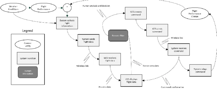
Figure 3: External system diagram of Phase III data control loop.
24
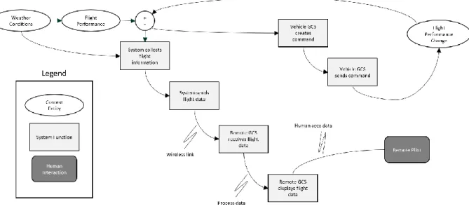
Figure 4: External system diagram of the Phase I and II data control loop.
The weather and flight performance are measured by the system. That information is processed and sent to the remote ground station. The remote ground station processes the data and displays it for the remote operator. For Phases I and II this is the end of the open loop and the data will continue flowing through that sequence. However, for Phase III, the operator will be able to make decisions based on the information displayed on screen. In the case the operator needs to intervene in the nominal operation of the flight, a command is created at the remote ground station by the operator. Then, the command is sent to the on-board system where it is processed. Finally, the on-board system sends the command to the remote vehicle where the action desired by the remote operator is completed. The subsequent data collected by the system should confirm the change requested by the operator.
3.2.3 Objective Hierarchy
25
each sub-system was most important. The components represented by the hierarchy should define values to the stakeholders. The operational objective is:
Develop a robust communication system which provides the remote pilot in command the necessary data and command structure for mission success.
Each of the three sub-systems connect to this operational objective with their respective attributes. The following sub-sections detail the prioritized objective hierarchy for each of the sub-systems.
3.2.3.1 Data Collection
The data collection subsystem is comprised of the elements of the system which measure the flight characteristics of the vehicle during flight. The data collection subsystem is crucial for the system to perform correctly because the remote operator will have no direct visibility of the vehicle. Sensor data from the data collection subsystem is the only information with which the remote pilot will be able to make flight-critical decisions.
1. Reliability:
The data collection subsystem shall be capable of collecting data without data dropouts or misrepresented data. This capability is pivotal to the functionality of the system because bad or missing data cannot appropriately inform the remote operator's decisions.
2. Speed:
26
important as the reliability, but correct data which is reported slowly is more useful than incorrect data which is reported quickly.
3. Accuracy:
The data collection subsystem shall collect data which appropriately represents the state of the system. It does not need to perform highly precise measurements at the expense of reliability or speed. To avoid false indications of system issues, the system needs to provide accurate data, but highly precise data is unnecessary.
3.2.3.2 Data Processing
The data processing subsystem provides task management and data handling for the system in real-time. It is imperative that the data processing unit perform tasks without distortion of the data. Furthermore, the data processing subsystem is responsible for the timing of all the tasks for the system, so it is critical for this system to optimize functionality while reducing the amount of computation to reduce cycle times.
1. Reliability:
27
2. Prioritization:
The data processing subsystem shall control the order in which tasks occur if they cannot be run simultaneously. This task management will ensure that critical tasks are performed before tasks which are not as important for flight operations.
3. Multitasking:
The data processing subsystem shall run tasks simultaneously if possible. The ability for the data processing subsystem to handle multiple tasks concurrently in combination with the task scheduling prioritization will allow for complete control of the data collection, processing, and communication systems.
4. Speed:
The data processing subsystem shall function at a speed which does not inhibit the overall function of the system. If the data processing subsystem can prioritize and run processes simultaneously, the speed of the system should not be an issue, but a noted concern if processing tasks become too cumbersome for the processing unit.
3.2.3.3 Communication
28
1. Reliability:
The communication subsystem shall not lose data packets, garble data packets, or drop communication link during flight. There are methods for ensure the fidelity of the transmitted data but losing communication link could be devastating for the mission. Thus, a reliable system is imperative, with corrective actions that are taken if the data link is lost.
2. Speed:
The speed of the communication subsystem shall be within the allowable real-time limits for the operator.
3. Security:
The communication subsystem shall be secure to outside threat of hacking or other methods to illicitly gain control of the vehicle. For this thesis, no work will be put into the security of the system, but security will be necessary as the project progresses.
The limits of operation were vague in the section above. The details of the limits will be filled in during the system design section. For example, the speed at which data must be collected, processed, and transferred will depend on the needs of the system stakeholders and specific vehicle for which the system will be designed.
3.2.4 Stakeholder Needs
29
operational hierarchy was compiled. Following the guidelines in Lockheed Martin's Core System Requirements Specification the stakeholder needs were separated into functional, interface, non-functional, enabling needs (Martin, 12). Each need identified was linked to the justification for inclusion, derivation, and validation technique. An additional section was included to address constraints. The stakeholder needs represent the high-level elements of the operational concept which will be required to function as needed. As part of the description of each of the needs, their respective verification methods were also included. The verification methods take one of four forms:
• Demonstrate: The need is verified by the system without any external equipment.
• Test: The need is verified using an external piece of equipment.
• Analyze: The need is verified through logical conclusion or mathematical analysis.
• Inspect: The need is verified by visual inspection.
3.2.4.1 Functional Needs
The functional needs correspond with actions the system shall be capable of performing. At its core, this system serves as a relay between the remote operator and vehicle which means the functional needs of the system are related to the communication system. These parameters can be qualitative or quantitative depending on whether they are performance metrics or general functional needs.
1. The system shall reliably connect with the remote ground control station (GCS) and
vehicle command and control system:
30
board the vehicle and GCS in the external system diagram combined with the reliability ranked highest in the objective hierarchy. There is no metric associated with this need, but it necessitates a demonstration of the system's robust qualities for verification.
2. The system shall support wireless communication with the remote ground station:
Wireless communication between the system and remote GCS is the central purpose of the system for Phases I, II, and III. Data must be transmitted from the sensors on the vehicle to the remote GCS to provide the remote operator with data that can inform any flight-critical decisions. This need was derived from the external system diagrams. It is verified by the system demonstrating the capability of the communication system.
3. The system shall store data if collection rate is higher than transmission rate:
There are cases where the flight data collection rate will be higher than the rate at which the information can be transmitted to the remote GCS. In these cases, the system shall be able to store data at the highest rate while sending less data to the remote GCS. This need was suggested by the stakeholders to ensure high-fidelity data is recorded somewhere if the communication system does not have the bandwidth. It is verified by demonstration.
4. The system shall contain logic for multitasking:
31
rates in parallel to ensure higher priority tasks are executed in a timely manner. This need is derived from the operational hierarchy and is verified by demonstration on the system.
5. The system shall possess the capability to verify the integrity of data passing in and out:
A major issue with data transfer systems, especially high frequency data transfers, is packet garbling. This means that somewhere between the data collection and data display for the operator, the data changed. Thus, incorrect information was displayed for the remote operator which could cause an unnecessary alarm. This need was identified from the operational hierarchy. It is verified by demonstration of the ability to transmit data without misinterpreting data. Alternatively, it can be verified by intentionally testing the system with a garbled packet to see the response.
6. The system shall have a power system which can sustain it for at least the duration of a
flight:
32
7. The system shall control data collection rates:
The system controls all the tasks for data collection and transmission. Based on the analysis of data collection and transmission times, the system shall regulate the rates at which these processes are performed to provide the remote operator with the most accurate flight information. This need was derived from the operational hierarchy. It is verified by the analysis of data collection and transmission rates.
8. The system shall have the bandwidth to send/receive data at a rate consistent with the
data collection:
The bandwidth the communication system has for transmitting data shall be consistent with the amount of data which needs to be collected and sent to the remote GCS. This will depend on the specifics of the data collection and communication systems. It is derived from the external system diagrams and objective hierarchy and is verified through analysis coupled with demonstration.
9. The system shall have sensors capable of detecting the current inertial state of the
vehicle:
33
10.The system shall have sensors for determining flight speed characteristics:
The system needs to communicate to the remote operator where the vehicle is in space and what speed it is traveling. This is derived from the need to ensure flight performance is within limits as described in the operational concept. It is verified by inspection and demonstration.
11.The system shall be capable of data transmission with the vehicle control system:
Data transmission to the vehicle is the key feature of the Phase III system. For Phase I and II the system does not need to communicate with the vehicle, but this connection provides the remote operator control of the vehicle. In addition to the physical communication link with the vehicle, the system must also be able to send the correct command signal such that the vehicle can execute the command. This need was derived from the external system diagrams and is verified by the demonstration of capabilities.
3.2.4.2 Interface Needs
Interface stakeholder needs define the interfaces with external systems. These interfaces include the physical size constraints and the communication interfaces.
1. The system shall fit in the payload compartment with a standard mission payload:
34
the vehicle and not interfere with the main payload. This need was derived from the full operational concept. It is verified by inspection and analysis.
2. The system data storage shall be accessible via wired link, wireless link, or removable
card:
The data on the system shall be accessible once the vehicle has completed its mission so that the full-fidelity data can be analyzed. This may occur by cable, card, or wireless communication. This need was identified through the operational concept post-flight tasks. The verification method is demonstration.
3. The system software shall be accessible by wired or wireless computer connection:
The system will be programmed with scripts loaded into memory which will be run on the vehicle. That software must be accessible for modification through a wired or wireless connection. This was derived from the operational concept mission planning section. The verification method for this need is demonstration.
3.2.4.3 Non-Functional Needs
The non-functional needs of the system define characteristics such as reliability, maintainability, safety, and environmental requirements.
1. The system shall not be a cause of electromagnetic interference (EMI) for the vehicle
control or communication systems:
35
ensure no issues prior to flight. This need is verified through analysis and testing prior to flight.
2. The system shall not move the CG beyond the limits of the vehicle:
The placement of the system shall also not influence the stability of the vehicle in a significant way. The CG of the vehicle shall not move beyond the limits specified by the manufacturer. This need was identified in the operational concept at the installation task. It is verified by inspection and analysis.
3. The system shall not increase the weight of the vehicle beyond the max takeoff weight:
The system needs to remain as light as possible to impact the performance and payload carrying capability of the vehicle as little as possible. This was derived from the operational concept installation task. During installation the weight of the should be measured prior to installation to ensure the weight limit is not breached. The verification process for this need is through testing the weight with a scale.
4. The system shall be robust to normal flight vibration:
36
5. The system shall be robust to physical shock impact landings on the ground:
The system shall be able to withstand normal conditions of the vehicle, which may include harsh landings and failed takeoffs. In lieu of characterization of these events via some measurement, the system shall be over-engineered to handle shock events. This need was derived from stakeholder input. The verification of this need is possible through demonstration or analysis.
3.2.4.4 Enabling Needs
The enabling needs describe the production, development, testing, training, support, deployment, and disposal of the system.
1. The system components shall be readily available:
To reduce the burden on the design process, any components selected for the system shall be readily available. This need is verified by inspection.
2. The system components shall be technology which already exists:
The design process for this system is not the platform for developing new technologies. Thus, the components selected for the system shall already exist and be available. This need is verified by inspection.
3. The development of the system shall stay within budget:
37
4. The development of the system shall remain within the time schedule:
The development process will have a project timeline which needs to be considered. This time constraint is validated through inspection.
3.2.4.5 Constraints
The constraints pertain to how the system will be built and deployed. The listed items attempt to identify and solve the tradeoffs which may be found during development.
1. The system reliability and fidelity shall take precedent over communication speeds:
It is more important that the correct information be transmitted to the remote operator than the information be transferred quickly. This need is derived from the operational hierarchy. It is validated by demonstration.
2. The data collection speeds shall be verifiable using a software in-the-loop counter:
It will be most accurate to use the system for verifying the rates at which data is collected. The system is already controlling the rates, so reporting them should be trivial. This need is verified by demonstration.
3. The data transfer rate between the vehicle and remote data system shall be validated by
an on-board counter:
38
this data is to be collected and verified, it must be done by the system. Verification is through demonstration.
4. The data transfer rate between the remote GCS and data system shall be validated by the
GCS transfer protocol system:
The transfer rate between the system and the remote GCS can be calculated by the GCS. Given the much higher processing capability, any calculations which can be done on the GCS computer should be run there. This need is verified through demonstration.
3.2.5 Operational Concept Summary
The operational concept established the foundation for the development of a full system architecture. It identified the general vision for the system from the view of the stakeholders. The operational concept also served as a starting point for the concurrent development of the functional and physical architectures. By existing as a high-level description of the system functionality, the operational concept guides the description of how the inputs are converted to outputs in the functional and physical architectures. Due to the iterative nature of systems development, it was also modified during the continued development of the full system architecture. The information documented above was the final version of the operational concept after completion of the full system development.
3.3 Functional Architecture
39
stakeholder needs will be achieved in the final design of the system. The functional architecture sets out to describe the functions which will achieve the objectives posed by the operational concept. Concurrently, the physical architecture describes the elements of the system which can perform those functions.
The development of the functional architecture began by organizing the functions addressing objectives from the operational concept into a hierarchy. Then, the high-level functions which linked inputs and outputs of the system were identified. Third, the stakeholders were asked for input regarding the functional decomposition of the system. Finally, the inputs and outputs on the external system diagrams were linked to functions. In Buede's treatment of the functional architecture development, there is also a step for integrating fault tolerances and security functionality, but this step was ignored during this development due to time constraints. The continuation of this project should look into the safety and security of the system.
3.3.1 Functional Hierarchy
A hierarchy of the functions needed to satisfy the objectives presented by the operational concept contain details about the functions required to satisfy those objectives. This functional hierarchy includes functions which will be handled by the on-board system. There are corresponding functions which are employed by the remote ground station, but for simplicity only the on-board functions are represented in this decomposition.
3.3.1.1 Receive Commands from Remote GCS
40
remote operator is the most important data the system will handle. If the remote operator needs to provide input to the vehicle, that data should be prioritized because it may be critical to safety. The most important part of the function is ensuring data integrity. Secondary to the integrity of the command is a receipt so the operator is sure the sent command was received and executed.
3.3.1.2 Transmit Data to Remote GCS
The second most important function for the system is to transmit the collected data to the remote ground control station. This function is critical to the purpose of the system. If the data cannot be transmitted to the remote operator, the system is not functional. For the transmission function, data integrity is more important than speed and scheduling because it is crucial that the correct data be sent to the remote operator than fast data which is wrong. However, managing the speed and schedule is still important to the proper function of the system.
3.3.1.3 Collect Flight Data
41
3.3.2 Input and Output Relationships
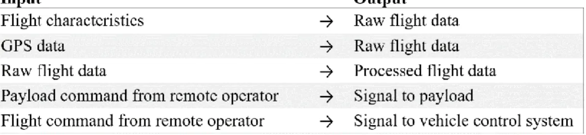
The functions of the system were provided more detail by resolving the input/output relationships more closely. The main reference for this was the simple external system diagram. The input/output relationships depend on data interactions due to the nature of the system. The relationships are displayed in Table 5.
Table 5: Functional input/output relationships.
The physical characteristics of the flight are recorded by the data collection system through a suite of sensors. Thus, the input into the system is the flight characteristics of the vehicle the system is on, and the output is raw flight data. The same is true for the GPS data collected by the system. It polls the GPS for position and records that data on board as raw flight data. Then, that raw flight data is processed by the on-board processing unit before being transmitted to the remote ground control station. This constitutes the input/output relationship of data from the vehicle dynamics to useful information for the remote operator.
42
command sent by the remote operator. This command is received, and the corresponding output is a signal to either the payload or vehicle depending on the command.
3.3.3 Stakeholder Input
Throughout the development process, the stakeholders were asked for input regarding the overall process and specific development details. Their input was critical for identifying many of the functional needs of the system. At the end, the system stakeholder was consulted to look for significant issues with the outcome of the development. Again, the stakeholders were able to provide insight and point development in a direction beneficial to the project without finding any major deficiencies in the functional development.
3.4 Physical Architecture
Along with the development of the functional architecture, the physical architecture is developed concurrently to ensure the functional needs can be met within manageable physical elements. Initially, these elements are vague, but as more focus is placed on functionality the specifics of the elements become clear. These elements can also be left vague to allow for more configuration during the specific design.
43
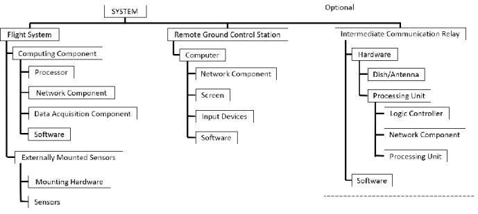
The physical architecture consists of three main parts under the overall system. First, the on-board subsystem called the flight system in Figure 5. Within that system is the main structure which will contain the processing, data acquisition, and communication units. Additionally, there is another element for sensors which may need to be mounted to the vehicle separate from the main structure.
Figure 5: The physical architecture of the system.
Second, the remote ground control station describes the elements needed for the remote operator to access the data collected by the flight system. All that is required of this system is a computer connected to the same network the flight system is on whether that be by direct radio, network, or internet.
44
revealed a possibility of using the system with an intermediate relay, so it has been included in the physical architecture. Functionally, its purpose would be to receive data from the flight system or remote ground control station and sending that data to the other. Although the intermediate communication relay exists in the architecture, it is not a required component of the system.
3.5 Operational Architecture
The operational architecture could be addressed with all the compiled information from the development of the system architecture. The operational concept describes the system using a composition of the results from the operational concept, functional architecture, and physical architecture. This operational architecture was used as the framework for applying design-specific requirements during the subsequent steps for this thesis.
3.5.1 Physical Component Functions
The functional and physical architectures developed in tandem are combined to reveal which parts of the physical architecture perform which functions. This provides more insight for the needs of the components which will eventually fill in the framework of the system architecture. The result of this composition is found in Figure 6.
45
Figure 6: Functions performed by physical elements of the system.
The remote ground control station processes and displays data received from the flight system for the remote operator. It also performs the function of creating the various commands to control the payload or vehicle during Phase II and III of development.
The intermediate communication relay only functions as a data transfer unit. It receives data from either the flight system or remote ground control station and send that data to the other system. Again, this system is not required, and should only be used if necessary. It has been in included in the architecture for completeness.
3.5.2 Functional Flow, Activation, and Control
46
is linked with an output, required inputs, and required controls to perform as expected. The functional flow, activation, and control table is shown in Table 6.
The scheduling control function is the feature of the on-board logical processing which prioritizes functions and tasks for the system. It is controlled by the code written to direct the task scheduling and requires a time input to properly assign the next task to run. For this reason, the scheduling control function is a required control for many of the subsequent tasks in the table because it is the function which controls the rest of the system.
Table 6: The functional flow, activation, and control for the system.
47
physical features of the system such as the sensors. The makes the functional flow, activation, and control diagram powerful for describing the system architecture.
In addition to the on-board functions, the process data at GCS, display data, and create commands at GCS functions are all occurring on the remote ground control station computer. These functions flow to receive data and display data to the operator. Then, with the operators decision-making ability in Phases II and III, a command can be issued to the system for controlling the payload or vehicle if needed.
The increased complexity of functions described by the functional flow, activation, and control table highlight the deepened understanding of the needs of the system. The table also reveals the interconnection between many of the elements of the system. With this heightened understanding of the system as a whole, the system architecture begins to take the form of a framework which could support specific design requirements.
3.6 Summary of System Architecture Development
48
4. PHASE I PROTOTYPE DEVELOPMENT
The development of the system architecture describing a framework for supporting ground station monitoring and control of a remote sUAS was the first segment of the full development process for this thesis. With the framework in place, an initial prototype of the Phase I design is desired by the AFL as a test platform for the operational concept. As a test platform, the first prototype will serve as the basis for all future work utilizing the system architecture and will serve the purpose of validating the system architecture. Thus, the stages for completing the prototype development are to fill in the system architecture with specific requirements, make design decisions based on trade studies, and finalize a detailed version of the prototype design. Following the completion of these steps, the prototype should be prepared for validation and testing.
Prototype development, combined with the earlier development of the system architecture, is an iterative process where the deficiencies in the design process can be addressed by reverting back to the issues and making logical changes to influence the design output. These modifications can be made in the design space or to parts of the system architecture. For this treatment of the prototype development, changes which were made to the system architecture will not be addressed, as there is only space for the final forms of the developed systems.
49
With the requirements in place, designs with specific components could be compiled. Trade studies of single components and combined design concepts were evaluated in various trades studies to determine which, if any, design options satisfy the requirements. In the end, many design options satisfied the requirements, which forced the stakeholders to add additional constraints and make design decisions based on the available options. Some of the additional considerations made were, user friendliness, long-term support, and familiarity with components of the designs. This design is the Phase I prototype which will be used to validate the system architecture and AFL-specific design. Furthermore, it will serve as the base for the continuation of the project into Phases II and III.
4.1 Requirements
The requirements used for the prototype development were derived from a combination of the two platforms the AFL intended to use the system on. These two vehicles are the fixed-wing Altavian Nova and the rotorcraft Aerovironment Vapor 55. The reason these two vehicles were chosen as the basis of the prototype development was that they offer different operational capabilities for testing the system. The differences in flight characteristics between the two vehicles vary in speed, acceleration, duration, and mission capabilities. The two systems encompass the range of vehicles the system is expected to work with.
50
requirements which were not identified as user needs during the system architecture development. If the new requirement was an oversight, they were added to the user needs section of the system architecture, otherwise, the new requirement was added as a stand-alone part of the requirement section. At the end, the ability for the requirements defined using the system architecture to support design options confirms that the system architecture was successfully defined for this application.
4.1.1 Functional Requirements
The functional requirements specify actionable behaviors of the system. The functional requirements follow the user need from the system architecture which they were derived from. The justification for the requirement follows.
1. The system shall reliably connect with the remote ground station and vehicle command
and control system:
The signal between the remote GCS and the system shall not be lost for more
than 8 seconds.
51
2. The system shall support wireless communication with the remote ground station:
The system shall communicate via wireless internet connection, local
network, or radio.
The long-term vision for the system requires that the data be transmitted from the vehicle to the remote GCS by a wireless internet connection. Thus, the capability to send data files over wireless communication shall be tested. For testing it is unnecessary to spend the money on a wireless internet contract because communication through a direct radio link or wireless network can act in place of the wireless internet. The local network would also demonstrate the ability to send data files, whereas the radio communication would show a serial data communication capability.
3. The system shall store data if collection rate is higher than transmission rate:
A minimum 8 GB data storage device such as an SD card or flash memory
chip shall be present to store data on board.
52
4. The system shall contain logic for multitasking:
The system processor shall be capable of multitasking or being programmed
as a task scheduler to simulate multitasking.
There are two implementations of processing units. A central processing unit (CPU) is capable of executing many tasks at once. CPUs are the chips which perform the logical processing for most computers. A microprocessor is a single chip version of a CPU which is only capable of executing a single task at once. Microprocessors are the chips at the heart of microcontrollers (MCU). Therefore, the integration of either of these two options will require a different software implementation to enable the execution of simultaneous tasks. With a CPU the processing unit has the capability by default, whereas with the microprocessor, a strategically programmed task scheduler will be required to meet this requirement.
5. The system shall possess the capability to verify the integrity of data passing in and out:
The system shall employ a check-sum algorithm for data transfer integrity
verification.
53
6. The system shall have a power system which can sustain it for at least the duration of a
flight:
The system shall have a battery life of at least three hours.
The three-hour battery life requirement is directly attributed to the flight time of the Nova. The Nova is listed with an 80-minute endurance. It was decided at least a factor of two was needed for the system in the case of a longer flight or other unexpected circumstance. The exact size of the battery is dependent on the power draw of the system. The Vapor endurance is around 30 minutes giving the system significant overhead for Vapor flights.
7. The system shall control data collection rates:
The logic system shall control the rate of data collection and communication.
54
8. The system shall have the bandwidth to send/receive data at a rate consistent with the
data collection:
The system communication bandwidth must be greater than 240
bytes/second.
The expected acceleration, rotation, heading, altitude, position, and power data is expected to yield a packet of about 50 bytes for the Vapor 55 and 60 bytes for the Nova. To support sending two packets of data each second, the communication system shall be capable of sending 240 bytes each second. A more capable communication would give overhead for extra data or higher communication rates which are desired for a more robust system.
9. The system shall have sensors capable of detecting the current inertial state of the
vehicle:
The system shall interface with accelerometers, gyroscopes, and
magnetometers for making inertial measurement.
55
10.The system shall have sensors for determining flight speed characteristics:
The system shall be interface with GPS and pitot-static air measurement
systems to determine flight characteristics.
The two methods for determining speed are using GPS and a differential pressure measurement. GPS can only provide ground speed whereas the pitot-static pressure measurement can provide airspeed. A combination of the two sensors shall be used to provide the operator with information about the speed and position of the vehicle. The Vapor 55 might only be able to support GPS speed because the pitot-static airspeed measurement requires free stream air. The down wash of the main rotor on the Vapor 55 will likely interfere with the forward airspeed measurement.
11.The system shall be capable of data transmission with the vehicle control system:
The system shall communicate through an RS-232 port and 16-pin
proprietary Altavian connector.
56
4.1.2 Interface Requirements
The interface requirements define the connections the system will have to external systems and components.
1. The system shall fit in the payload compartment with a standard mission payload:
The system shall be smaller than 7.5 x 4.5 x 4 inches.
The system shall be kept as small as possible to minimize the impact it has on the vehicles. The Vapor 55 has a large payload volume of 20 x 6.5 x 5 inches. This volume is partially filled by 12 x 5 x 4 inches of batteries but can be configured to handle a significant array of weight distributions. Furthermore, the Vapor has a mount for a camera not included in that volume, meaning that the mission payload does not interfere with the space for the system. The Nova has a smaller payload volume at 7.5 x 4.5 x 4 inches. Currently, it is unknown what size the mission payload will be, so a maximum limit has been placed on the system at the size of the Nova payload bay with the intent of keeping it much smaller.
2. The system data storage shall be accessible via wired link, wireless link, or removable
card:
The system data storage shall be accessed through a USB, SD card, or
wireless transmission.
57
can be accessed by pulling a data storage card out of the system and accessing that through another computer.
3. The system software shall be accessible by wired or wireless computer connection:
The system shall be programmed or accessed through a wired, network, or
Bluetooth connection.
The system will have scripts for running task management, data collection, and communication functions. This code shall be accessible for modifications through a wired, network, or Bluetooth connection. Either the code can be replaced with new code, or it can be modified on board if possible. This will allow for long term flexibility to add or change components.
4.1.3 Non-Functional Requirements
The non-functional requirements define overall operational characteristics of the system such as reliability, environmental, and safety.
1. The system shall not be a cause of electromagnetic interference (EMI) for the vehicle
control or communication systems:
The system communication shall not interfere with the vehicle
communication channels on 900 MHz, 902-928 MHz, and 2400-2485.3 GHz.