B
Biodex Medical Systems, Inc.IODEX
20 Ramsey Road, Shirley, New York, 11967-4704, Tel: 800-224-6339 (Int’l 631-924-9000),Fax: 631-924-9241, Email: [email protected], www.biodex.com
ADDENDUM
BIODEX EMG/ANALOG SIGNAL ACCESS
CONFIGURATION UTILITY SOFTWARE
FOR SYSTEM 3 REVISION 2 AND SYSTEM 4 DYNAMOMETERS
830-000
835-000
840-000
850-000
2 Biodex Medical Systems, Inc. © 2014
This manual contains operating procedures for the following Biodex products:
830-000 System 3 QUICK-SET
835-000 System 3 PRO
840-000 System 4 QUICK-SET
850-000 System 4 PRO
Need Help?
Contact Biodex Software Support
1-800-224-6339 ext 2120,
EMG/ANALOG SIGNAL ACCESS UTILITY SOFTWARE 3
Table of Contents
CHAPTER 1 - Overview ... 4 CHAPTER 2 - Installation ... 6 CHAPTER 3 – Operating Modes ... 11
4 Biodex Medical Systems, Inc. © 2014
1. Overview
The EMG/Analog Signal Access Utility (ASA Utility) is part of the EMG/Analog Signal Access Interface option for System 3 and System 4, Rev 2 dynamometers. The utility configures the scale factors and operating modes of the analog signal outputs for velocity, torque and position.
Auxiliary RS 232 for RTK interface
Remote Access for
EMG/ANALOG SIGNAL ACCESS UTILITY SOFTWARE 5 With the configuration capability, the analog signals can be custom tailored to provide the best and most appropriate analog data for a wide variety of usages.
The ASA Utility must be installed on the System 3 or 4 computer, which runs the Biodex application software. Insert the provided ASA Utility CD into the CD drive, and it will
automatically start the setup installation. If all the defaults are chosen during setup, a shortcut will be created on your desktop called: System 3 ASA Config.
The utility cannot be run simultaneously with the Biodex application. Typically you must exit the Biodex application, run the ASA Utility to setup the scaling and modes, and then run the Biodex application to perform your tests and data capture.
Through the Remote Access port is an output of analog signals of velocity, torque and position data in real-time directly from the motor control Digital Signal Processor (DSP). In addition to the real-time data, a synchronization pulse is issued whenever the real-time data is updated. The synchronization pulse can be used by the monitoring equipment to know when the real-time data output has changed.
A System 3 Rev2 or 4 is ready to output the analog signals of torque, position and velocity through the RS-232. This software utility manages those signals in a manner most suited for the application.
The RS-232 settings required are as follows:
19.2K BAUD, 8 data bits, 1 stop bit, no parity, no handshake
Minimum computer requirements (which the Biodex System 3 or 4 computer meets)
32 bit version of Windows (95/98/NT/2000/XP, Win 7), a minimum of 128 MB of memory (256 MB for 2000 and XP), and 2-3 MB of available disk space. The software is installed from CD via a SETUP program which will guide you through the process.
6 Biodex Medical Systems, Inc. © 2014
2. Installation
The ASA Utility software should be installed onto the System 3 or System 4 computer. Prior to installation, you should exit the Biodex application and verify which Serial Com port is used by the Biodex. The ASA Utility needs to have the same COM port selected to work as intended. Go to the Setup options in the Biodex application.
EMG/ANALOG SIGNAL ACCESS UTILITY SOFTWARE 7 Select Cancel and exit the application.
To install the ASA Utility software, place the installation CD in the DVD/CD ROM Drive. Click on the setup.msi file to install. Follow the set-up wizard prompts to install.
Once installed, a short cut will be created on the desktop. Click on the program icon to open.
8 Biodex Medical Systems, Inc. © 2014 Click on File, and select COM 1—the port that was identified earlier.
Mismatched COM ports is a common mistake in this process.
EMG/ANALOG SIGNAL ACCESS UTILITY SOFTWARE 9 Once you are ONLINE, make your scaling selections and exit the ASA Utility. Again, the System 3 or 4 Application software and the ASA Utility are not intended to run together.
Once the settings are made, the ASA Utility will be permanently set in the System 3 or 4, even if the unit is completely shut down and re-started. The current settings can always be verified by running the utility – it will show the current active settings. Status information on the System is shown on the top of the screen for your reference. As long as the status shows ONLINE, the current displayed Analog Signal settings are accurate.
The Signal Settings
Analog Signal Resolution Effected By Scale Factor
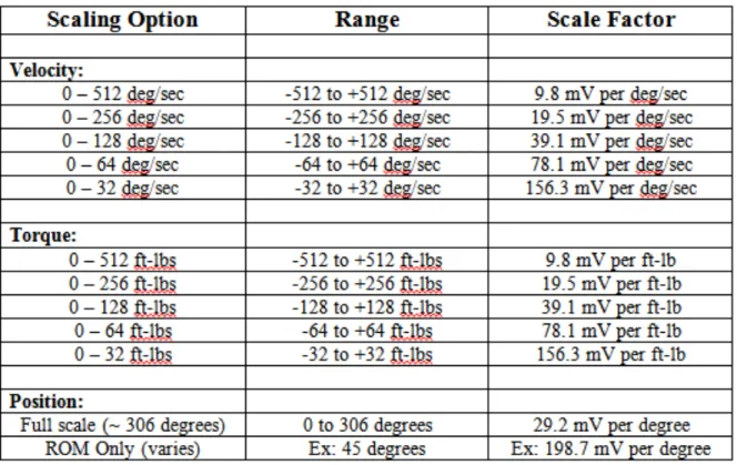
The analog signals range from –5 volts to +5 volts, resulting in a total range of 10 volts. With the standard Remote Access option available on a System 3 or 4 Rev 2, all analog output signals are at full scale (full scale being the default). Full scale for torque as an example is –512 ft-lbs to +512 ft-lbs, for a total range of 1024 ft-lbs. This results in an output resolution scale factor as follows:
1024 ft-lbs = 10 volts, 1 ft-lb = 9.8 milli-volts
10 Biodex Medical Systems, Inc. © 2014 9.8 milli-volts is well below the signal noise rated for this port, therefore it is not possible to see 1 ft-lb increments on this analog signal. The utility provides scaling options separately for all three analog signals, so if typical usage is well below the maximum levels, 1 ft-lb increments can be seen on typical analog monitoring equipment. For example, applying a range of +/- 0 to 64 ft-lbs, the output resolution scale factor would look as follows:
128 ft-lbs = 10 volts, 1 ft-lb = 78.1 milli-volts
78.1 milli-volts is well above the worst case of signal noise (15 – 35 mV), so increments as low
EMG/ANALOG SIGNAL ACCESS UTILITY SOFTWARE 11
3. Operating Modes
The Output Frequency, or update rate, controls how frequent the System will change the analog outputs. The highest update rate is 2,000 times per second, which is the default. If this high frequency is not needed or may even be causing problems with the monitoring equipment, the update rate can be lowered. Every time the analog signals are output, the synchronization signal is pulsed also. Therefore the update rate controls how frequent the synchronization signal is pulsed.
The Output Mode selects in what state the analog signal outputs are updated. The Options are as Follows:
On Always - always output irregardless of current operational state
On Timed - turns on analog outputs only for the next fixed period of time (in seconds)
Off (disabled) - totally shuts down the analog signal outputs
Auto, when active - is automatically on only when the system is in an active state, meaning not STOP’ed and not in HOLD
On Go command - synchronizes the analog signal output with the System 3 application’s GO command, so the output is performed only during the trials exercised
Table of Scale Range and Factors
There are many different types of devices that someone could connect to. As such, we provide the “pin outs” and leave it up to the end user to make the interface cable. Because of the popularity of this application, many companies have cables available for their devices. You may want to check with your particular interface device manufacturer. If not, you can make a cable to communicate if you know the other device’s connections.
12 Biodex Medical Systems, Inc. © 2014 The connection is labeled REMOTE ACCESS on the back of the Biodex CDS cart. It is a DB-15 female connector.
EMG/ANALOG SIGNAL ACCESS UTILITY SOFTWARE 13 BNC Cable example.
14 Biodex Medical Systems, Inc. © 2014
Specifications:
Accuracy: ± 2%.
Resolution: 16 Bits.
Minimum Vout Increment: 152.5uv
Signal Noise:
15 mVrms [20KHz Bandwidth].
35 mVpp [20 µS minimum, 150µS maximum width].
Response Time: 500µS.
Connector: DB-15 male “D” Connector.
Output Short Circuit Duration: Infinite.
Output Impedance: 100S
Individual Signals
Torque* Analog torque signal 5 volts is cw torque (512 ft-lbs) 0.0 volts is 0 ft-lbs
-5.0 volts is ccw torque (512 ft-lbs) Scale Factor= 9.76 mV/ft-lbs.
Velocity Analog velocity signal
5 volts is full scale cw speed (512 deg/sec) 0.0 volts is 0 deg/sec
-5.0 volts is full scale ccw speed (512 deg/sec) Scale Factor= 9.76 mV/[deg/sec]
Position Analog position signal
4.60 volts is when dyna shaft is fully cw -4.28 volts is when dyna shaft is fully ccw Scale Factor= 28.7 mV/[deg]
Total ROM is 306 degrees; Total Vout =8.88V
Synchronization Digital TTL pulse
Active High
29µs Pulse width Continuous
16 Biodex Medical Systems, Inc. © 2014