2008 10th Intl. Conf. on Control, Automation, Robotics and Vision Hanoi, Vietnam, 17–20 December 2008
Multiple Target Tracking with an Efficient Compact
Colour Correlogram
Pankaj Kumar, Anthony Dick, Michael J. Brooks
School of Computer ScienceUniversity of Adelaide Adelaide, Australia
[email protected], [email protected], [email protected]
Abstract—A robust approach to detection and tracking of multiple moving targets from a moving camera is presented. The main novelty of this approach is that objects are represented using efficient compact form of the colour correlogram. Like previous correlograms, this encodes both spatial pattern and appearance information about the target. However it is less complex to compute, making it applicable to real time target tracking. The correlogram representation is incorporated into a particle filter tracking framework. Robustness to camera motion is obtained by identifying homographies linking adjacent frames, and using them to align corresponding image areas to a common local reference frame. We demonstrate successful detection and tracking in real life image sequences.
Index Terms—Video Surveillance, Moving Cameras, Detection, Tracking, Particle Filter, Multiple Cue, Correlogram
I. INTRODUCTION
Tracking multiple interacting targets in video generated from a moving camera is a difficult, challenging, and im-portant problem in computer vision. Tracking in complex environments requires object detection, a discriminative object representation, and a dynamic estimation framework that does not constrain camera or object motion. In this paper we address these three aspects of tracking in order to achieve a robust and complete tracking algorithm for tracking multiple targets.
Automatic detection of independent moving targets has been shown to be useful not only for automatic initialization of tracking but also for recovery from errors due to drifting to background regions of the frames [1], [2]. Jinman Kang
et. al.[3] proposed calculation of pixel statistics by tracking pixel’s location in a window of several frames using the affine transform. Further more in [4] Kanget. alapplied extra constraints of epipolar geometry and structure consistency to the above detection, to more precisely detect independently moving pixels when there is strong parallax in the scene due to the translation of camera center and lack of planarity in the scene.
We propose a general homography transform to align pixels to the common location corresponding to the reference frame in a window of frames. The statistics of each pixel in the reference frame is modelled with Gaussian distributions and then statistically compared to detect foreground pixels in the reference frame. This method is shown to be robust for detection of targets in videos from PTZ cameras and for cases where the background is planar. Simultaneously is it simple enough for real time implementation.
Histograms are commonly used for target representation in tracking applications. Histograms have proven to be robust to partial occlusions, and changes in size, shape and rotation because they discard spatial information. However the loss of spatial information reduces specificity in the model, thus increasing the susceptibility to distraction by the background or other objects. It is desirable for robustness to include spatial information in the representation such that shape and size invariance is still maintained. Thus there have been several approaches to incorporate some spatial information in the target representation. Birchfield and Rangarajan [5], [6] came up with spatiograms, which are histograms augmented with spatial mean and covariances to capture richer description of the target. More recently Zhao and Tao [7], [8] used correlogram based representation in a mean-shift framework for tracking pose and position of an object simultaneously. The computation and representation of correlograms is more expen-sive than histograms; thus it will be difficult to expect them to work in real time for multiple target tracking applications. We propose a reduced version of the full correlogram which is discriminative in target representation and can be computed as efficiently as a histogram. We then apply the correlogram based representation in a multiple cue particle filter framework, which is well suited to multiple target tracking and can integrate multiple feature cues for estimation of the state vector of the target.
The contributions of this paper are:
1) An algorithm to detect independently moving objects in image sequences captured from a moving camera (Section II).
2) A novel colour correlogram object representation which is efficient to compute (Section III).
3) Use of proposed correlogram in a particle filter frame work for tracking multiple targets (Section IV).
II. DETECTION OFMOVINGOBJECTS
The usual paradigm for detection of pixels on a moving object in frames from a stationary camera, is to observe pixels for a period of time. Based on these observations a statistical model of each pixel in the frame is built. If a pixel’s obser-vation differs significantly from the learnt statistical properties of that pixel then the pixel is considered to be from a moving object [9], [10]. The underlying assumption of this approach
is that the colour of a pixel at a particular location in an image sequence is generated from the same 3D location of the scene, unless occupied by a moving object. This fundamental assumption is violated when the camera used for observations is non-stationary. To align frames from a moving camera we use a homography transform H computed automatically between frames using feature correspondences and RANSAC estimation. The homography transform [11] can align frames when the camera center is fixed or when the scene being observed is planar. These conditions are usually true of videos generated in surveillance systems which use fixed mounted PTZ cameras or cameras on Unmaned Aerial Vehicles (UAV). For alignment of frames and generation of statistical models of pixels we consider frames in a sliding window of width W around the reference frame It, that is It−W/2, It+1−W/2, ..., It, ..., It+W/2−1, It+W/2. The
Harris corner detector is applied to each frame in the window and features are matched across frames using cross correlation. Matched features are then used to estimate the homographies Ht−W/2, ...,Ht−1,Ht+1, ...,Ht+W/2
using the RANSAC method. Each frame
It−W/2, It+1−W/2, ..., It−1, It+1..., It+W/2−1, It+W/2 is
generated by applying the inverse transform H−1 with linear interpolation.
Thus for a pixel in the reference frame we have W corresponding pixels fromW/2 past and W/2 future frames. This means that processing for detection of moving objects has to be done at a time lag ofW/2 frames. To build a statistical model of a pixel in reference frame It at location (i, j) a histogramHij(u)of theW aligned pixels is built, whereuis the bin index. A window of size2×ωaround the mode of the histogram is used to compute the parameters of the Gaussian distribution used to model the pixel.
μij =(umax 1 ij +ω) u=(umax ij −ω)Hij(u) (umaxij+ω) u=(umax ij −ω) u×Hij(u) (1) σij= (umax 1 ij +ω) u=(umax ij −ω)Hij(u) (umax ij+ω) u=(umax ij −ω) (u−μij)2×Hij(u) (2) The process is repeated for each channel under the assumption that channels are independent and covariance is a diagonal matrix with cross-covariance terms equal to zero. In our computations we use W = 50andω= 10.
If the background has motion due to moving leaves, reflec-tive surfaces etc. then these can be modelled by adopting a mixture of Gaussians to model each pixel.
For detection of foreground pixels in the reference frame each pixel in the reference frame is compared with the corre-sponding pixels statistics:
|pijt−μijt|> β×σijt (3)
where pijt is the intensity of one colour channel at pixeli, j in the reference frame, μijt is the mean value of the pixel at i, j, and σijt is the variance of the pixel values. β is an
(a) (b)
(c) (d)
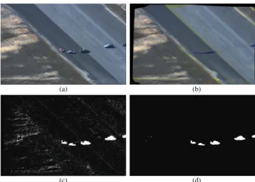
Fig. 1. (a) is a reference frame 411 from PETS2005 dataset sequence EgTest02 (b) is the mean background model of the image sequence with the proposed methods. (c) and (d) are the raw detection results of moving targets and the morphologically filtered detection results, respectively.
empirical threshold parameter. If the above equation is satisfied for two or more colour channels then the pixel is classified as a pixel on a moving object. Pixels detected this way are morphologically filtered and connected into blobs using eight connected component analysis. Each connected component whose pixel count is greater than a threshold is enclosed by a bounding box whose length, breadth and position is measured for data association with current targets being tracked. Figure 1 shows a reference frame and the background model for this reference frame and detection results.
III. COLOURCORRELOGRAM BASEDTARGET
REPRESENTATION A. Overview and Definition
Correlograms are tables showing how the autocorrelation of a signal changes with distance. Spatial analysts adapted this idea to spatial distance [12], and Huang [13] adapted the idea to the spatial separation of pixels in an image to arrive at colour correlograms. The colour correlogram (henceforth correlogram) of an image encodes both colour distribution and spatial distribution of pixels in an image. The correlograms were originally used for indexing and retrieval of images based on a query. As the correlogram of an imageIis a table indexed by colour pairs and distance, the size of a correlogram ism2d where m is the number of bins for colour quantization and d the number of quantized distances between pixels in the image I. Because m2d is large for computation and storage, a subset, the autocorrelogram, was considered for encoding images. Autocorrelogram is a correlogram that includes only the correlation of identical colours; therefore its size is md. Zhao and Tao [7] came up with another simplified version of the correlogram where only fixed distances along major and minor axes were considered. The size of this correlogram was of the order O(m2). The correlogram was employed for tracking single objects in a 3D mean-shift based algorithm. The advantage of the use of the correlogram in tracking is that
(a) (b)
Fig. 2. (a) shows the pictorial representation of an object defined byl, b,and
θin image space. (b) shows a pixel pair around central axis and how they are considered for computing the proposed Colour Correlogram.
both translation and rotational movement of object is tracked simultaneously. The disadvantage of the use of correlogram is its high computational requirement.
We present a new correlogram representation which is much faster to compute and can be applied straightforwardly to a particle filter algorithm for tracking multiple targets. The advantage of the proposed correlogram over previous representations is that it is as efficient to compute as a colour histogram. As it is developed for colour pixels, it is more discriminative than gray scale correlograms.
B. Reduced and Simplified Version of Correlogram
An object in an image frame I is defined by its length l, breadth b and orientation θ. θ is the angle between the horizontal axis of the image and one side of the object, as shown in Figure 2 (a). For the generation of correlogram we consider pairs of pixels which are equidistant from the central axis of the object, as shown in Figure 2 (b).
The colour channels in imageI are each quantized intom binsc1, ..., cmand the distance between pixel pairsp1, p2 and the central axisCa are quantized intod bins dist1, ..., distd. Then the correlogram is defined as
γdistk
ci,cj prob[p1∈I(ci), p2∈I(cj),
|p1−Ca|=|p2−Ca| ∈I(distk)].
whereI(ci) andI(cj) is the colour range for bins ci and cj respectively andI(distk) is the distance range for bindistk. Note that the indexi, jused here are different from those used in equations (1) and (2).
The proposed correlogram is a subset of the full correlogram but it is adequate to differentiate between images which have almost identical histograms. Figure 3 (a) (b) shows two bilevel images whose histograms are identical while their proposed correlograms are significantly different 3 (c) (d). We chose a bilevel image for demonstration purposes because the colour pairs are limited to black-black, black-white, white-black, and white-white and distances are quantized to five bins, so the graphical representation of correlogram is simplified.
The advantage of the proposed correlogram is its compu-tational efficiency. If n is the total number of pixels in the region defined byb, l,andθthen the order of computation for computing correlogram by our method is only O(n) where as for previous methods it is at least O(nd) where d is the number of distance quanta considered.
(a) (b)
(c) (d)
Fig. 3. (a) and (b) are two bilevel images with identical histogram but different spatial arrangements of pixels. (c) and (d) are their correlogram, respectively. In plots (c) and (d) y-axis is the bin score and on x-axis are different bin pairs with different distance bins. The four possible pixels pairs for are: black-black, black-white, white-black-black, and white-white. Distance amongst pixel pairs are quantized to five different levels namely,dist1, dist2, dist3, dist4,
anddist5. The correlogram of images (a) and (b) are substantially different although their histograms are identical.
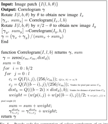
Input:Image patch {I(l, b, θ)}
Output:Correlogram γ
Rotate I(l, b, θ)byθ to obtain new imageIx
[γx, sumx] =Correlogram(Ix, l, b)
Rotate I(l, b, θ)byπ/2−θto obtain new imageIy
γy, sumy =Correlogram(Iy, b, l) γ=γx+γy /(sumx+sumy) End
function Correlogram(I, l, b)returnsγ,sum
γ=zeros(cm, cm, distd);
sum= 0;
f or i= 0 :b/2
f or j= 0 :l
ci=Q(I(i, j),(256/cm));Q(a, b) =a/b
cj=Q(I((b−i), j)/(256/cm));%index for pixel pair acrossCa distk =Q(((b−2i)×distd), b);%index for distance of pixel fromCa
weight= (w(p(i, j) +w(p((b−i), j))/2; %w(p(i, j))is pixel weight [2]
sum=sum+weight;
γdistk ci,cj =γ
distk
ci,cj +weight; returnγ
Fig. 4. Pseudo code for computation of colour correlogram of an image region.
For objects symmetrical along axisCa and having identical histograms but differing in arrangement of patterns aroundCa as shown in Figure 5 (a) (b), this version of the correlogram fails to differentiate images, as shown in Figure 5 (c), (d). In such a case considering pixel pairs along axis perpendicular to Ca solves the problem and results in different correlogram as shown in Figure 5(e) (f). The time complexity of computing this correlogram is stillO(n). Pseudo-code for computing the correlogram of a single channel image region defined byl, b, θ is shown in Figure 4.
(a) (b)
(c) (d)
(e) (f)
Fig. 5. (a) and (b) are bilevel images with identical histogram but different spatial arrangements of pixels. (c) and (d) are correlogram for distance across axisCa. The values on x-axis and y-axis are same as those for Figure 3. (e) and (f) are correlogram for distance across axisCa and axis perpendicular toCa. Correlograms (c) and (d) are identical but considering distance across axis perpendicular toCaresults in discriminative correlogram (e) and (f).
IV. INTEGRATION INTOPARTICLEFILTER BASED
TRACKING
Zhao and Tao [7] integrated their colour correlogram in a mean-shift tracking algorithm for tracking a single target in complex scenarios. Our motivation is to be able to track multiple interacting objects in complex situations. Therefore we integrate the correlogram into a particle filter based tracking method. Particle filter based trackers maintain multiple hy-potheses of targets being tracked and therefore are more robust in recovering from errors which usually occur when multiple targets undergo occlusions and cross overs. Additionally, the mean-shift tracking algorithm requires a differentiable simi-larity measure where as for particle filter a non-differentiable likelihood measure will do. We use theL1norm for computing the match measure between target correlogram model and candidate correlogram.
A. Target State and Representation
A target is represented by its state Xt and its correlo-gram model. The state of a target is expressed as Xt =
[xc, yc, l, b, θ]T wherexc, yc are the centroid co-ordinates and l, b are the length and breadth of the object and θ is its orientation in the image frame. Correlogram of a target is a set of three probability distributions of the three colour channels
RGB, Xγ={[γdistk ci,cj]R,[γ distk ci,cj]G,[γ distk ci,cj]B}. (4) During computation of the probability distribution [γdistk
ci,cj] the pixels of the image region are weighed by the distance
transform weightw(pi)[2], which has been shown to be more effective than the usual Epanechnikov kernel weight.
B. Hypothesis Generation and Evaluation
We use the Sequential Importance Resampling (SIR) al-gorithm for computing the approximation of the probability density function (pdf) of the state vectorXt. In this algorithm the hypothesis/particles are redistributed with equal weights according to the posterior pdf of the state vector in the last iteration. We use a random walk motion model to generate hypothesis/particles for the next iteration. Xs
t+1 = Xts+vt where vt is independently distributed zero mean Gaussian noise.
Each hypothesis of the target state is evaluated in the current observationZtusing correlogram modelXγ and segmentation information. A likelihood function is used to compute the weight of each hypothesis integrating correlogram and seg-mentation cues.
L(Zt|Xts) =Lcorr(ZCM,t|Xts)× Lseg(Zseg,t|Xts), (5) where
Lseg(Zseg,t|Xts) = exp (−Dseg(Xts, Zsegq t)/σzseg), (6) Zq
segt is the measurement(x q
c, yqc, lq, bq, θq)of the blob from the current frame which matches the target being tracked. Dseg(Xs t, Ztq) = (1−exp (−λ)and λ= [||X s t −Ztq||2 ls×bs ] (7)
In case of merge, where two or more targets merge to give rise to one measurementλis obtained as follows
λ= [(x s
c−xmq)2+ (ysc−ymqc )2
ls×bs ] (8)
where xmq
c , ymqc is the weighted centroid of the foreground pixels in the region defined by hypothesis Xs
t in the current detection result.
1) Correlogram based Hypothesis Evaluation: Previous methods of colour based appearance model for tracking has used the Bhattacharyya coefficient for computing the like-lihood [2], [14], [15]. The proposed correlogram is sparse as most of its elements are zero therefore the Bhattacharyya coefficient is not good for differentiating between similar and dissimilar appearance models. Therefore we propose to use the L1 norm for computing the match measure between the target correlogram model Tγ and the correlogram model of the hypothesisXs
γ in the current frame. Thus the likelihood
Lcorr(Zγ,t|Xts) =exp( −Dcorr(Tt,γ, Xt,sγ) σZcorr ) (9) and Dcorr(Tγ, Xγs) =mi=1mj=1dk=1 |T[γdistk
ci,cj]R−X[γdistkci,cj]R|+
|T[γdistk
ci,cj]G−X[γdistkci,cj]G|+|T[γdistkci,cj]B−X[γdistkci,cj]B|
here the time subscript t has been dropped for simplicity of representation.
C. Target Model Update
To handle the appearance change of the object due to variation in illumination, pose, distance from the camera, etc., the object model is updated using the auto-regressive learning process
Tt+1,γ= (1−α)Tt,γ+αXt,estγ. (10) Here Xest
t,γ is the correlogram of the region defined by the
mode of the particles used in tracking the object, andαis the learning rate. The higher the value of α the faster the object model will be updated to the new region. The model update is applied when there is one to one matching between the target and measurements from the current reference frame. In case of merge or split the target model is not updated.
V. RESULTS
For quantitative evaluation of tracking based on the pro-posed correlogram object model against a colour histogram based object model we use a synthetic image sequence with a static background. The object to be tracked is an overlaid image of a car which rotates clockwise and shrinks in di-mension and then expands in didi-mension. We use this image sequence because ground truth is easily generated by simple frame differencing, using the background image. Figure 6 (a), (b), and (c) shows the tracking results using the colour histogram and 6 (d), (e), and (f) shows the tracking results by the correlogram based object model. We compute and plot two errors for tracking of this sequence:epos is the position localisation error by the tracker and is computed as
epos=|xct−xcgt|+|yct−ycgt| (11)
andeθis the orientation tracking error computed as
eθ=|θt−θgt| (12)
Plot 7 shows the quantitative evaluation of tracking. Errors epos and eθ are plotted on y axis against frame numbers on the x-axis. The correlogram based tracker has lower overall errors for both position and orientation tracking as compared to the colour histogram based tracking. The average position tracking error (epos) per frame by histogram model is 5.85 pixels where as by the correlogram model is 4.66 pixels. The average orientation tracking error(eθ)by the histogram model is 2.54 degrees where as by the correlogram model is only 0.88 degree. This is due to the incorporation of spatial information in the correlogram based object model, where as there is no spatial information in the histogram based object model. In all our experiments we use as little as 50 particles per target to track them. Better results can be obtained by using more particles.
Figure 8 shows the tracking results on sequence egtest02
from PETS2005 dataset. The tracking results are shown by different colours and patterns of bounding boxs on the vehicles. We choose not to show the trace because the camera is moving. The vehicles have been correctly tracked for position and orientation in spite of their small size, a moving camera and poor quality of the video. Here the tracker failed during cross
(a) (b) (c)
(d) (e) (f)
Fig. 6. (a), (b), and (c) shows the tracking results using the colour histogram model and (d), (e), and (f) shows the tracking results using the proposed correlogram model. The tracking of position and orientation by the correlogram object model is better than by the colour histogram model.
(a) 0 100 200 300 400 500 600 0 1 2 3 4 5 6 7 8 9 Frame numbers eθ histogram correlogram (b) 0 100 200 300 400 500 600 0 2 4 6 8 10 12 14 Frame numbers epos histogram correlogram
Fig. 7. (a)plot of orientation tracking errors for each frame of the image sequence. (b) plot of position tracking errors for each frame of the sequence. The errors by the correlogram tracking is less than the errors by the colour histogram tracking.
overs. This is because the colours and patterns of the vehicles are very similar, they are small in size, and the quality of the video is poor. Figure 9 shows tracking of people in an image sequence from a moving camera. Here there are no changes in orientation but because of combining colour and segmentation cues in a particle filter frame work the targets has been correctly tracked in spite of almost complete and partial occlusions. From design prespective there is no constraint on the number of objects that can be simultaneously tracked. But as the number of objects increases the computation load also increases.
VI. CONCLUSIONS
An enhanced scheme for tracking multiple objects in video has been proposed and demonstrated. Novel contributions of this work include detection of moving objects in image sequence from a moving camera, a new efficient correlogram
(a) (b)
(c) (d)
(e) (f)
Fig. 8. (a), (b), (c), (d), (e), and (f)shows the tracking results on theegtest02 sequence. The corresponding frame numbers in the sequence are 301, 385, 420, 440, 460, and 500. The tracking results are shown by different colours and patterns of bounding box on each target. In spite of the small size of the targets and a moving camera the position and orientation of the vehicles have been correctly tracked.
(a) (b)
(c) (d)
(e) (f)
Fig. 9. (a), (b), (c), (d), (e), and (f) shows the tracking results on image sequence of people moving. In spite of targets being almost completely and partially occluded and cross overs the people have been correctly tracked.
model to simultaneously track the orientation and position of targets, and integration of correlogram and segmentation cues in a particle filter frame work for robust tracking of objects. It has been quantitatively demonstrated that the proposed correlo-gram model based tracking is more accurate than the histocorrelo-gram model based tracking. The measurement obtained from moving object detection is integrated with the correlogram cue to achieve better localisation of the object. The integration of two cues improves handling of objects model undergoing change, rendering the system less susceptible to the drift problem. Furthermore the tracker can follow a target with as few as 50 particles. But when the objects being tracked are similar in colour and patterns then the proposed approach will be unable to disambiguate them during cross overs. In cases where the background doesnot satisfy the planarity condition then more complex detection algorithm [4] can be used.
REFERENCES
[1] P. Kumar, S. Ranganath, K. Sengupta, and H. Weimin, “Co-operative multi-target tracking and classification.,” in ECCV (1), pp. 376–389, 2004.
[2] P. Kumar, M. J. Brooks, and A. R. Dick, “Adaptive multiple object tracking using colour and segmentation cues,” inAsian Conference on Computer Vision, pp. 853–863, 2007.
[3] J. Kang, I. Cohen, and G. Medioni, “Continuous tracking within and across camera streams,” inProceedings of the IEEE Computer Society Conference on Computer Vision and Pattern Recognition, pp. 267–272, 2003.
[4] J. Kang, I. Cohen, G. Medioni, and C. Yuan, “Detection and tracking of moving objects from a moving platform in presence of strong parallax,” in Proceedings of the Tenth International Conference on Computer Vision, vol. 1, (Beijing, China), pp. 10–17, 2005.
[5] S. T. Birchfield and S. Rangarajan, “Spatiograms versus histograms for region-based tracking,” in CVPR ’05: Proceedings of the 2005 IEEE Computer Society Conference on Computer Vision and Pattern Recognition (CVPR’05) - Volume 2, (Washington, DC, USA), pp. 1158– 1163, IEEE Computer Society, 2005.
[6] S. T. Birchfield and S. Rangarajan, “Spatial histograms for region-based tracking,”ETRI, vol. 29, pp. 697–699, october 2007.
[7] Q. Zhao and H. Tao, “Object tracking using color correlogram,” in IEEE Workshop on Visual Surveillance and Performance Evaluation of Tracking and Surveillance (VS-PETS) in conjunction with ICCV, pp. 263–270, 2005.
[8] Q. Zhao and H. Tao, “Motion observability analysis of the simplified color correlogram for visual tracking,” inAsian Conference on Computer Vision, pp. I: 345–354, 2007.
[9] C. Stauffer and W. Grimson, “Adaptive background mixture models for real time tracking,” inProceedings of Computer Vision and Pattern Recognition, pp. 246–252, June 1999.
[10] P. Kumar, S. Ranganath, and W. Huang, “Queue based fast background modelling and fast hysteresis thresholding for better foreground segmen-tation,” in Proceedings of the ICICS-PCM 2003, vol. 2, (Singapore), pp. 743– 747, 2003.
[11] R. Hartley and A. Zisserman, Multiple View Geometry in Computer Vision. Cambridge University Press, 2000.
[12] G. J. G. Upton and B. Fingleton,Spatial data analysis by example, vol. 1. John Wiley & Sons, 1985.
[13] J. Huang,Color Spatial Image Indexing and Application. PhD thesis, August 1998. available at www.cs.cornell.edu/home/huang/thesis.pdf. [14] C. Dorin, R. Visvanathan, and P. Meer, “Kernel-based object
track-ing,”IEEE Transactions on Pattern Analysis and Machine Intelligence, vol. 25, no. 5, pp. 564–577, 2003.
[15] K. Nummiaro, E. Koller-Meier, and L. J. V. Gool, “Object tracking with an adaptive color-based particle filter,” inProceedings of the 24th DAGM Symposium on Pattern Recognition, (London, UK), pp. 353–360, Springer-Verlag, 2002.