The 5th International Power Engineering and Optirnization Conference (PEOC02011). Shah Alarn. Selangor. Malaysia: 6-7
June 2011
Smart Grid Co
mm
unication Concept for
Frequency Control in Distribution System
J.J. Jamian, Student Member, IEEE, M.W. Mustafa, Member, IEEE, H. Mokhlis, Member, IEEE,M.A. Baharudin
Abstract- The advancement of electrical device technologies can be used to balance tbe frequency of the system by adjusting their power consumption. However, this can only be achieved by having good data communication management. The introduction of Smart Home System (whicb consists of Smart Appliance (SA) and Smart Meter (SM», Smart Regional Server (SRS) and Smart Server (SS) will be used to manage data communication in smart distribution system. The communications between these devices will be via Power Line Communication (pLC), and WiMAX will be used as a medium to transfer the data to the SRS. Transport Control Protocol (TCP) will increase the reliability of transferring data. By having good communication and architecture, as weD as good management and decision making by the servers and smart metering, the use of load-balancing control to maintain the frequency of the system within the acceptable limit in smart distribution grid system will be achieved.
Index Terms- smart distribution gird; communication; data management; controllable load; priority factor.
I. INTRODUCTION
T
HERE are many parameters that need to be considered during the planning process of a power system, either in generation, transmission or distribution side such as frequency level, voltage level, capacity limit of each components and etc. By considering all these parameters, the power system can operate without any problem that might give an impact to the consumer and utility. In traditional power system, generators have been used to balance out the frequency between power generation and load, and many techniques have been introduced [1-5]. We can define this type of system as "generation-balancing control" method. If the system detects instability in the frequency, the generation will vary its output to fulfil the requirement of demand.On the other hand, in smart grid system, the controllable load such as washing machine, dishwasher, electrical car, water heater and other intelligent devices can be used to implement the "demand-balancing control" method. In [6], the
advantages of controlling load to composite the fluctuation of renewable energy (RE) rather than using Energy Storage System(ESS) has been discussed. The controllable loads not only have a fast response, but are also more reliable in solving the imbalanced frequency problem [12]. Besides that, the controllable load will also eliminate the total power loss which occurs in ESS during switching process (power switching losses). By controlling the controllable load, the power curve can also be flattened. By adjusting their time of operation, for
instance, operating the intelligent device only at light load condition and stop the operation or reduce the total power consumption during peak load, the controllable load will reduce the congestion that occurs in the system.
However, the smart grid requires a good data communication management and architecture. So, the main objective of this paper is to propose a smart grid concept applied in distribution system for maintaining the system frequency within the allowable range. The proposed concept is more on the communication aspect that are required in order to control the load demand in a smart house. The remaining of this paper is structured as follows. The following section introduces the detail of communication technologies that should be implemented in smart distribution grid to achieve the objective of this paper. Section III describes the topology of the smart distribution network. Section IV describes the priority approach that is used to determine the contribution of each load and the paper ends by presenting the conclusion and future works.
II. HYBRID COMMUNICATION MANAGEMENT
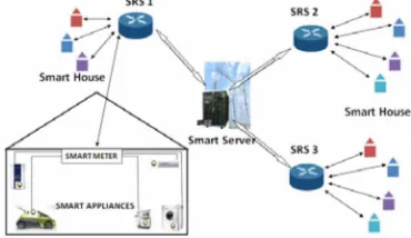
Protocols and techniques for communication are already well developed and efficient. It would be a waste of time and resources if we are to recreate a new set of protocols for this new system. We do not have to reinvent the wheel. Thus, it is desirable to integrate the current existing protocols and technologies into this new smart distribution system. The network topology of the system is as illustrated in Fig. 1. The main entities in the system are the Smart Server (SS) which is located at the substation, the Smart Regional Server (SRS) which is located in specific regions supported by the substation, the Smart Meter (SM) located at each house and the Smart Appliances (SA).
[image:1.612.338.523.578.685.2]A. Local (In-home) Communication Management
According to [10], PLC is proposed as the communication medium between the home appliances (HA) in each home with its smart meter (SM). PLC is a good choice, due to the reduced cost needed for installation, because the medium of communication used is already installed in the building beforehand. Nonetheless, PLC is not the only means that can be used as the communication medium. Current researches, such as in [8], are looking into wireless sensor networks (WSN); a group of sensor nodes (compliant to IEEE802.15.4) which are deployed to monitor the condition of an area or a system, and send the data wirelessly to the base node. These nodes can be deployed into the each of the sockets available inside a house, and collect the power consumption from each socket and send it to the SM.
In [9], a simple device to tum on or off a device which communicate to the appliances via PLC was introduced. Furthermore, there is also a controller device developed by the Pacific Northwest National Laboratory. This device, which is installed in appliances, will tum the appliance off for a few seconds up to a few minutes when it detects frequency changes in the power grid. The concept implemented by this controller is similar to the load shedding technique. However, this device works independently and is not organized by a specific controlling entity. Thus, if it is implemented in all of the appliances in the household, when a frequency drop occurs in the grid, all of these appliances will tum off simultaneously.
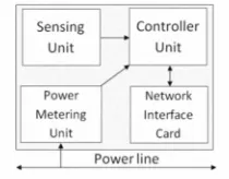
The process for the stabilizing the frequency of the system will also become harder. Hence, with the aim of creating a smarter environment, we would like to propose a conceptual module to be implemented to the HAs which would enable the HA itself to detect the state that it is in and schedule its task completion according to the prioritization settings by the user. The structure of the proposed module is as depicted in Fig. 2. This module should be embedded inside each appliance which will be labelled as smart appliances (SA). In example, a washing machine with this module can be configured to start operating at 8 am and finish washing at 8 pm in the evening. So in this time interval, this machine will operate when the load in the grid is at a low level and tum to standby mode when the smart meter receives a command from the SRS to lower the load.
The power metering unit is the entity which calculates the power consumption of the appliance and sends the data to the controlling unit. The sensing unit is the entity that senses the condition of the appliance either in term of temperature or etc. The Network Interface Card (NIC) is the entity which will modulate and send the data in the uplink direction and demodulate and transfer the information received in the downlink direction to the upper layers. This entity usually consists of the two lowest layers in the communication stack which is the Physical layer (PHY) and the Medium Access Layer (MAC). The controller unit will act as the brain for this module. It will get the data from the power metering unit and send it to the SM via the NIC. It will also sense via the sensing
the SM. With the implementation of this module, the system will be fully automated. Plus, users can set their preferences in these modules so that when power reduction command is received, it will act according to the user preferences.
Fig. 2. Conceptual Module to be implemented into HAs.
B. Smart Meter to Smart Server via Smart Regional Server
According to [7], the characteristics of PLC used in domestic scenarios (low voltage) such as in homes or offices are different from industrial scenarios. Furthermore, it is still unknown whether the usage of PLC with the transmission line is applicable. This fact renders the PLC unusable in this situation. Thus, it is in our interest to propose the use of existing communication technologies which has already been deployed and is operational currently. Besides using PLC, there are other options, in example, physical network connections such as ADSL and fiber optics and Wireless technologies such as 3GPP L TE and WiMAX. The drawback of using physical connection between SMs and the SRS is that there is a need for each home to have physical connection installed. Unless each home already has its own physical connection to the internet, the installation cost will be big. On the other hand, by implementing wireless backhaul connection to the Smart Regional Server (SRS), some installation cost can be reduced. For instance, WiMAX can be used because its coverage is very wide (around 50km radius) with very fast bitrates (up to 30Mbps or more). Even at the cell edge, the speed is still around I to 4 Mbps, which is more than enough
to send the data collected by the smart meter. The WiMAX interface cards can be embedded in the smart meter.
The communication between the SRS and the SS will be done using physical connection either by using ADSL or Fiber Optics via the internet. This is feasible because the number of SRS will not be as many as the number of SMs. In addition, communication via physical connections will be faster and more reliable.
C. Protocol Stacks of the Entities in the System
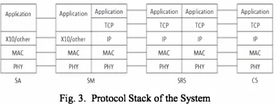
The data collection is one of the most crucial parts in this system. Data losses can disrupt the accuracy of the smart grid load distribution system. In [10], the authors introduced a three layer protocol stack which consists of an appliance layer at the topmost part, network layer in the middle and the physical layer at the bottom. According to [9], the network layer used in [10] is likely to be the XIO protocol [13]. An enhancement of
[image:2.612.376.481.130.212.2]sending data to the designated server, congestion and collision which causes packet drops is bound to happen. The network layer, which mostly consists of the IP protocol, does not support packet retransmission and reordering. For this reason, we would like to propose the use of transport layer in the communication protocol stack. Transport layer protocols such as TCP and SCTP supports these capabilities, and can guarantee a reliable connection between the SMs and the SS.
The proposed protocol stack is as shown in Fig. 3. The transport layer, TCP in particular, will be added in the protocol stacks of the SM, SRS and SS. The network layer of the SAs can be either using the XIO protocol or the enhanced version in [9].
AppfuOOn Application Application Application Application Application
TCP TCP TCP TCP
XIO/other XIO/other IP IP IP IP
MAC MAC MAC MAC MAC MAC
PHY PHY PHY PHY PHY PHY
SA SM IRS C5
Fig. 3. Protocol Stack of the System
III. PROPOSED ARCHITECTURE FOR SMART GRID
The detail of two main components in network topology of the smart distribution grid proposed above is discussed below.
A. Server Operation Method
The smart server (SS) will be used to sense the frequency change in the network and calculate the total load that needs to be adjusted based on the frequency slope as proposed in [II]. So, during the frequency fluctuations, the SS will determine the total amount of load consumption that needs to be changed. Next, it will refer to its database to determine the available load changing amount in each SRS and send the data signal to selected SRS. However, the decision is made based on two main criteria which are the larger amount of load changing availability in SRS area and the maximum reduction of power losses between SS and SRS after adjustable load take an action. The two criteria have been chosen due to general formula of power system balancing as shown in equation (1), where P is the real power.
�hangtt(ss)
=�djustment
+�oss�SS-SRS)
(1)
The changes of controllable load consumption in smart grid system will also affect the power losses. For example, for the two regions which have the same amount of controllable load availability, but the distance between these two areas are different, by choosing the region who will give maximum
power losses reduction (e.g.: the region further away), we might reduce the total load adjustment. Without considering the power losses, the surplus power reduction might occur and cause frequency fluctuations again. Fig. 4 shows the value of
load adjustments that need to be reduced due to consideration of reduction in distribution system during frequency fall condition.
Fig. 4. Relationship between power adjustment and distance
The amount of load adjustment which is requested by SS will be sent to the selected SRS through the internet. When the SRS receives the command to adjust the power consumption in its own region, it will forward the massage to selected SMs (houses). Again, the selection process of SM will also use the same method as SRS process which is based on their availability of load adjustment and maximum reduction on power losses as shown in equation (2). Even though the SS database consists of the total amount of availability of load adjustment for the regional area, the specific contribution of each houses is only stored at SRS database.
llPchangtt(srs)
=llPchangtt(ss) - �oss�SS-SRS)
=
�djUstment
+�OSS�SRS-SM)
(2)
After the SM gets the signal for adjusting their power consumption from SRS, it will ask the smart appliance to reduce/increase their power consumption in order to improve the frequency of the system. The optimization technique is used to make the selection of SA. However, the smart meter will also consider the time that has been set in some SAs by the user for completing their jobs. Once SA takes the action either increase or lowering its power consumption, the SA will update the latest condition to SRS through SM. The SS will also know the changes in SRS and update its own database. So, if there is any change in load consumption at SA, the SM, SRS and SS will update their database instantaneously. Fig. 5 shows the summary of the process in smart operation grid for the distribution system.
Smart Server (SS) sense tke frequency drop in the system
Decide amount of load (leW) mould be reduced bMe on frequency slope
SM report to SRS & 55 the amount of load that
stin av5iWlIc to adjust
SRS receive the siena! � NO Action will betaken
C
I
SA report to SM theSent the task to selected SM whith is base on maximum availability of adjustinC load value at their
Fail to complete thetesk
---.. --"'YES
�
L---_____ Adjustment NO
comoleted?
[image:3.612.341.509.71.148.2] [image:3.612.89.286.231.306.2] [image:3.612.325.549.487.664.2]B. Categories of Load in Smart Distribution Grid System
All Smart Appliances (SA) will be embedded with the module in Fig. 2 that allows the SA to communicate and control or change their power consumption. However, each SA has different capabilities and functions. So, in this paper, the SA will be categorised into 3 major types based on their operation type and the ability to control their load.
1) Thermal Based Load
For a SA which has heat storage capability, it can be turned on and off for certain seconds up to certain minutes without affecting their temperature such as refrigerator, water heater and etc. So, during the peak condition or losing generation sources, these types of load can be turned off for a certain time to help the system regenerate. However, the SM also needs to consider the marginal time before the load can be turned on again. For instance, the refrigerator cannot be turned on immediately after turning off as to avoid damage to the compressor and to lengthen its life span. So, these type of load is more suitable to be adjusted if the power system requires large amount of power adjustment in a long interval (tens minute).
2) Operation Mode Based Load
For the load that can function in multi mode of operating condition, the SM will ask the SA to change their mode when needed. However, the changing of mode operation is depending on agreement that has been approved by the consumer and it will not affect the consumer's comfortableness. Air conditioner is one of the examples of SA unit under this category. So, the user can set the range of the operation like from 19°C up to 25°C during day time, and the smart meter will run the analysis to decide the suitable temperature that will be allowed depending on frequency of the system. So, multi mode load type is the most suitable approach that can be used to improve the frequency of the system. However, it will depend on consumer willingness and incentive from government.
3) Operating Time Based Load
Washing machine and dishwasher are the examples of electrical devices that can delay or postpone their operation without giving a big impact to the consumer. So, the consumer only needs to set the completing time that is required by them and the SM will determine the suitable time of operation for the devices. For example, if the consumers want the dishwasher completing its job before he or she returns home at 5 pm, the SM will run the machine during light load of system. However, this type of load will be at lower priority of load changing if the remaining time for the device to complete the task is shorter. So, there will be prioritization concept in SM decision making. Not only that, the use of electrical vehicle (EV) in future will also be categorised under this type of load. The EV is not only charged during suitable condition and complete the charging just before the time that has been set by the consumer, but it also can support the power to balance the frequency by discharging its supply. So, the large amount of EV in the future will increase the capacity storage and back up
IV. DISCUSSION
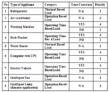
From the types of load that has been categorised above, an example of the priority factor is shown in Table I. The SM will only determine the contribution of each load after the priority factor of each appliance has been assigned. The comfort factor, time constraint factor and economic factor are the main factors to decide the priority for each load. Most of these factors are based on the agreement between the user and the power provider. The modem optimization method such as PSO can be used in decision making level in order to optimize the contribution of all appliances. Although some of the loads are required to delay or reduce their power consumption, they can help other devices to operate without frequency disturbance and with high reliability.
TABLE I
ASSIGNED OF PRIORITY FACTOR TO INTELLIGENT APPLIANCES
No TyptofAppli ... t Category TimeColL5tnin Priority
1 RMri�u.tor ThuLoad m.ll Rued N/A
2 AircGnd.iticmu Load Opention BUM N/A
Optra�Timt YH
3 Wuhi�lbcb.inf BufdLold
NO
Optrl�Timt YES
4 DilhWuhtr
ButdLold NO
WltuHuter Therm.ll Blud N/A Load
OpeIti�Tjlllt YES
6 Computu mth UPS BludLOId
NO
1 £lKtric'"ehidt BandLeOptrlt:iJLg, Time td YES
NO
8 Intt1lig.tllt Fit!. OpentionBuM N/A
Load
9 Intt1li�.e.t Lmlp (dimmU'appJicatioD) Load OptrltiOD. Rutd .·IA
Furthermore, by assigning the pnonty factor to all controllable loads, the process of flattening the power demand curve also becomes easier. The utilities also can maximize their operation and increase the efficiency either in generation side or transmission side. So, the load adjustment will not only give the impact to the distribution side, but it gives benefit to the whole power system.
V. CONCLUSION AND FUTURE WORKS
This paper proposes the alternative method to stabilize the frequency of the system by adjusting controllable load at distribution side. By using the proposed communication system and data management, the power system is able to operate at higher reliability without frequency disturbance and reducing the chances of system failure. In summary, the following major contributions have been made in this paper.
1. The module proposed in this paper will enable two way communications for the SA and gives SM the ability to change the SA's mode. So, it will make the dynamic load changing become possible.
[image:4.612.334.521.263.422.2]3. Many parameters need to be considered during the decision to adjust the load consumption such as the availability of load adjustment, effect of power losses and etc. The use of priority factor for each types of appliances make the decision making become easier.
Since so far this work is only proposing a conceptual smart grid application, further works need to be conducted in order to prove that the concept is possible for real implementation. In the near future, a simulation work will be carried out to study the response of the frequency system when loads are being adjusted from the network. Then, the communication elements will be considered in the simulation since the data communication may affect the effectiveness of the frequency control.
VI. REFERENCES
[I] Soder, Lennart; "Explaining Power System Operation to Nonengineers," Power Engineering Review, IEEE, vol.22, no.4, pp.25-27, April 2002. [2] Xiangning Lin; Hanli Weng; Qing Zou; Pei Liu; , "The Frequency
Closed-Loop Control Strategy of Islanded Power Systems," Power Systems, IEEE Transactions on, vol.23, no.2, pp.796-803, May 2008. [3] Verma, V.; Singh, B.; Chandra, A; AI-Haddad, K.; , "Power
Conditioner for Variable-Frequency Drives in Offshore Oil Fields," Industry Applications, IEEE Transactions on , vo1.46, no.2, pp.731-739, March-april 201 O.
[4] Fountas, N.A; Hatziargyriou, N.D.; Orfanogiannis, C.; Tasoulis, A; , "Interactive long-term simulation for power system restoration planning," Power Systems, IEEE Transactions on, vol.12, no.I, pp.61-68, Feb 1997.
[5] Rajagopal, V.; Singh, B.; Kasal, G.K.; , "Electronic load controller with power quality improvement of isolated induction generator for small hydro power generation," Renewable Power Generation, lET , vol.5, no.2, pp.202-2\3, March 2011.
[6] Podmore, R.; Robinson, M.R.;, "The Role of Simulators for Smart Grid Development," Smart Grid, IEEE Transactions on, vol.l, no.2, pp.205-212, Sept. 2010.
[7] Ginot, N.; Mannah, M.A.; Batard, C.; Machmoum, M.; , "Application of Power Line Communication for Data Transmission Over PWM Network," Smart Grid, IEEE Transactions on, vol.l, no.2, pp.178-185, Sept. 2010.
[8] Gungor, V.c.; Bin Lu; Hancke, G.P.; , "Opportunities and Challenges of Wireless Sensor Networks in Smart Grid," Industrial Electronics, IEEE Transactions on, vol.57, no.IO, pp.3557-3564, Oct. 2010.
[9] Rozeha A. Rashid; Mohd Adip Sarijari; Mohd Rozaini Abd Rahim; Tan Zun Yung;, "Flood Transmission based Protocol for Home Automation System via Power Line Communication," Proceedings of the International Conference on Computer and Communication Engineering, May 2008.
[10] Seunghyun Park; Hanjoo IGm; Hichan Moon; Jun Heo; Sungroh Yoon; , "Concurrent simulation platform for energy-aware smart metering systems," Consumer Electronics, IEEE Transactions on , vol.56, no.3, pp.l918-1926, Aug. 2010.
[II] Brooks, A; Lu, E.; Reicher, D.; Spirakis, C.; Weihl, B.; , "Demand Dispatch," Power and Energy Magazine, IEEE, vol.8, no.3, pp.20-29, May-June 2010.
[12] Moslehi, K.; Kumar, R.;, "A Reliability Perspective of the Smart Grid," Smart Grid, IEEE Transactions on, vol.l, no.l, pp.57-64, June 2010. [13] Zhang Yuejun; Wu Mingguang;, "Design of wireless remote module in
X-IO intelligent home," Industrial Technology, 2005. ICIT 2005. IEEE International Conference on , vol., no., pp.\349-\353, 14-17 Dec. 2005.
VII. BIOGRAPHY
Jasrul Jamani Jamian obtained is B. Eng. (Hons) in Electrical Engineering in 2008 and M. Eng. Electrical (power) in 20 10 from Universiti Teknologi Malaysia (UTM), Johor Bahru, Malaysia where he is currently pursues his Ph.D. degree. His current research interests include smart grid system, power system stability, renewable energy application and their control method.
Mohd Wazlr Mustafa received his B. Eng Degree (1988), M. Sc. (1993) and PhD (1997) from university of Strathclyde. He is currently an Associate Professor and Deputy Dean of Postgraduate Study and Research at Faculty of Electrical Engineering, Universiti Teknologi Malaysia (UTM), Johor Bahru, Malaysia. He research interest includes power system stability, FACTS and power system distribution automation.
Razlle Mokblis (M'OI) received his B. Eng in Electrical Engineering in 1999 and M. Eng. Sc in 2002 from University of Malaya, Malaysia. His obtained PhD degree from the University of Manchester, UK in 2009. Currently he is a Lecturer in the Department of Electrical Engineering, University of Malaya. His main research interest is in distribution automation area and power system protection.