73:3 (2015) 29–33 | www.jurnalteknologi.utm.my | eISSN 2180–3722 |
Full paper
Jurnal
Teknologi
Mobile Electrical Capacitance Tomography (ECT) Development for
Liquid-Gas Flow Measurement
Chan Kok Seonga, Jaysuman Pusppanathana, Ruzairi Abdul Rahima*, Yvette Shaan-Li Susiapana, Fatin Aliah Phangb, Mohd Hafiz Fazalul Rahimanc, Zubaidah Awangd, Anita Ahmada, Herman Abdul Wahida, Elmy Johana Mohamade, Suzanna Ridzuan Awa,f
aControl & Instrumentation Engineering Department, Faculty of Electrical Engineering, Universiti Teknologi Malaysia, 81310 UTM Johor Bahru, Johor,
Malaysia
bCentre of Engineering Education (CEE), Universiti Teknologi Malaysia, 81310 UTM Johor Bahru, Johoor, Malaysia
cTomography Imaging Research Group, School of Mechatronic Engineering, Universiti Malaysia Perlis, 02600 Arau, Perlis, Malaysia
dLanguage Academy, Universiti Teknologi Malaysia, 81310 UTM Johor Bahru, Johor, Malaysia
eDepartment of Mechatronics and Robotics Engineering, Faculty of Electrical & Electronics Engineering Universiti Tun Hussein Onn Malaysia, Pt. Raja, Bt. Pahat, Johor 86400, Malaysia
fFaculty of Electrical & Automation Engineering Technology, Terengganu Advance Technical Institute University College (TATiUC), Jalan Panchor, Telok Kalong, 24000 Kemaman, Terengganu, Malaysia
*Corresponding author: [email protected]
Article history
Received :15 August 2014 Received in revised form : 5 January 2015
Accepted :10 February 2015
Graphical abstract
Abstract
Electrical capacitance tomography (ECT) system is useful to obtain information on spatial distribution of dielectric material mixture inside a vessel. This paper discusses a sixteen-electrode mobile ECT sensing system which is developed non-invasively and non-intrusively. Emphases on the software development aspects are presented in several sections; initialization part, normalization part, calibration part, hardware communication part and the image reconstruction part. Thus, the liquid-gas concentration profile of the ECT system is successfully acquired using the software developed.
Keywords: Process tomography; electrical capacitance tomography; image reconstruction; multiphase flow measurement
© 2015 Penerbit UTM Press. All rights reserved.
1.0 INTRODUCTION
Process Tomography is a technique of obtaining images of a cross section of an industrial process, for example, a multi-phase flow in an oil pipeline, so that the internal behavior can be investigated [1]. Normally, Process Tomography system consists of three main units - sensor unit, sensing electronics unit and image reconstruction unit. The sensor is mounted directly onto the process equipment and the sensing electronics are located at the site of measurement. The image reconstruction computer may be located far away from the process, for example, in the central control room, as the site may be hazardous.
Generally, electrical capacitance tomography (ECT) is a technique used to obtain information about the distribution of the contents of closed pipes or vessels by measuring variations in the dielectric properties of the material inside the vessel [2,11]. It is appropriate for imaging industrial multi-component processes involving non-conducting flow materials. The main principle in
ECT is based on the standing capacitance, which is a function of the permittivity of the medium between the electrode plates over the entire sensing volume [3]. The spatial resolution of a tomographic imaging system depends on the number of independent measurements and fineness of sensitivity focus for each measurement. The measured values or data will be manipulated in order to reconstruct a cross sectional image of the pipeline by computer programming [4].
Figure 1 Overview of the project
2.0 ECT SENSOR CONFIGURATION
The choice of the number of electrodes around the circumference of the sensor is a trade off between axial length and radial length [6]. As the number of electrodes increases, the electrode surface area per unit axial length decreases and the inter-electrode capacitances also decrease. When the smallest of these capacitances (for opposite electrodes), reaches the lowest value that can be measured reliably by the capacitance circuitry, the number of electrodes, and hence the image resolution, can only be increased further by increasing the axial lengths of the electrodes. However, these lengths cannot be simply increased as the standing capacitances between pairs of adjacent electrodes will also increase and the measurement circuitry will saturate or overload once the highest capacitance measurement threshold is exceeded [5, 12].
A 16-electrode mobile sensor has been designed on a 110 mm diameter acrylic pipe circumference. An integrated signal conditioning circuit is embedded on each electrode sensor. These sensing plates are covered by a copper insulator layer known as earthed-screen which is designed using double layer Printed Circuit Board (PCB).
The ECT sensor needs to be firmly attached onto the surface of the pipe as any small movement between these electrodes will affect the inter-electrode capacitance of the sensors. Figure 2 shows a cross-section of the pipeline, represented by a circle divided into sixteen equal sectors with a 22.5o angle for each
[image:2.612.56.288.58.194.2]sensor. The total width for one sector is 21.6mm as shown in Figure 2.
[image:2.612.322.574.60.114.2]The PCB dimension is 19mm x 180mm and the sensing zone is 15 mm x 100 mm at the bottom layer. A 2 mm track space separates the sensing area and the earth screen as in Figure 3.
Figure 2 Sensor allocation with angle θ = 22.50
Figure 3 Sensing plate PCB
[image:2.612.322.556.231.331.2]An ideal capacitance measuring system should have a low noise level, a wide dynamic measurement range and high immunity to stray capacitance. Output signal from the sensor plate flows into an AC based capacitance measurement circuit and is measured in order to get the capacitance value between the electrode pair. A single complete sensing module is shown in Figure 4.
Figure 4 Sensing module
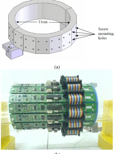
A customized sensor gripper with a diameter of 11cm is fabricated to firmly hold all sixteen sensing electrodes on the pipe. This sensing module can work independently without a host control. A single pair of the sensing module can work as a complete system. The advantage of this design is that it provides users the capability to increase or decrease the number of electrode sensors by reconfiguring the handling gripper as illustrated in Figure 5 [6].
(a)
(b)
[image:2.612.348.533.468.719.2] [image:2.612.81.252.576.731.2]3.0 SOFTWARE PROGRAMMING
The software in this research can be divided into several parts, which are the initialization part, the normalization and calibration part, the hardware communication part, the image reconstruction part, the concentration calculation part and the error measurement part.
First, the graphical user interface (GUI) automatically initializes the system. The initialization includes loading the sensitivity map of the linear back projection algorithm (LBP). Then the system will acquire measurement data from the sensors via a data acquisition system (DAQ). When two non-homogeneous dielectric materials are to be imaged, the calibration process takes place by measuring two reference sets of inter-electrode capacitances with the lower and higher permittivity materials respectively [6].
All subsequent capacitance values are then normalized from 0 (when the sensor is filled with the lower permittivity material) to 1 (when filled with the higher permittivity material). The normalized value of the ECT data will be used to reconstruct a cross sectional image by implementing LBP algorithm [7].
3.1 Microcontroller Firmware
The firmware of the microcontroller (PIC16F876 and PIC18F4550) is written using HITECH- C language using MPLAB programming software platform. The compiled firmware is loaded into the microcontroller through In Circuit Debugger (ICD2), a real-time debugger and programming device. ICD2 supports In-Circuit Debug functions, whereby the programs can be downloaded, executed in real time and examined in detail with the debug functions of MPLAB.
3.2 Sensing Module Firmware
The firmware is loaded into PIC16F876 which is embedded on all 16 electrode modules. The task of this slave firmware is to read commands from the central control unit (master), switching sequence of each electrode as excitation source or receiver and ADC data control (as in Figure 1).
3.3 Firmware for Central Control Unit
The central control unit is designed using PIC18F4550 in order to synchronize the whole operation. This initialization includes setting the microcontroller’s configuration and establishing a USB communication with a PC. The microcontroller is set to operate in pairing mode to enable double-buffering of the USB buffers. With double-buffering enabled, the microcontroller can store data in one buffer while the other buffer is being transferred over USB, thus increasing the processing time [8].
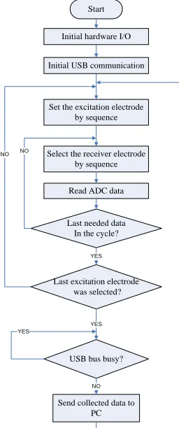
Next, the microcontroller will send the control sequence to the sensing modules, where each module will be switched as excitation electrode in turn [9]. The microcontroller will collect measurement data by sending commands to sensing modules (slave). Figure 6 shows the flow chart of the firmware as described above.
Start
Set the excitation electrode by sequence
Last excitation electrode was selected?
Send collected data to PC
NO
Initial hardware I/O
Initial USB communication
Select the receiver electrode by sequence
Read ADC data
Last needed data In the cycle?
NO
YES
USB bus busy?
YES YES
[image:3.612.374.502.59.365.2]NO
Figure 6 Firmware’s flow chart for Central Control Unit
3.4 Graphical User Interface (GUI)
One GUI is designed to perform several tasks such as online and offline measurement, display tomogram image result, select different image reconstruction algorithm, display the distribution of materials in the pipeline and others [10]. Figure 7 shows the mainframe of the GUI.
[image:3.612.325.558.505.676.2]The analysed result can be displayed in cross sectional view section of the GUI and its numeric data or bar graph form. There is also an online mode or offline mode selection. The online mode performs real-time measurement which is suitable for online monitoring application while offline mode collects and saves all measurement data at specific locations for offline analysis.
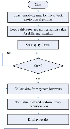
The calibration process has to be repeated in case different dielectric material takes part in the area of interest. The basic flow chart of the GUI is shown in Figure 8.
Start
Set display format Load sensitivity map for linear back
projection algorithm
Load calibration and normalization value for different materials
Start?
YES NO
Collect data from system hardware
Normalize data and perform image reconstruction
Display results
Figure 8 Basic flow chart for ECT system
4.0 RESULT AND ANALYSIS
Based on a pipeline with a diameter of 110 mm and 6 mm pipe wall, three types of flow condition were observed; water/air flow, water/oil flow and oil/air flow.
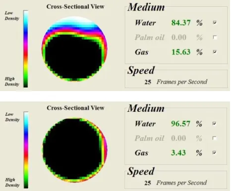
[image:4.612.114.236.171.393.2]Figure 9 Reconstructed image obtained of different flow concentration of water / air two phase flow
The cross-sectional image result reconstructed in Figure 9 was captured in real-time. The processing speed for a single image reconstruction is 25 frames per second. Lower density material (air) is represented by the color white while higher density (water) is represented by the color black based on the color map range.
5.0 CONCLUSIONS
An Electrical Capacitance Tomography System with mobile sensor design is successfully developed in this research. The two phase non-homogeneous dielectric materials are investigated and the results obtained is adequately satisfying.
The system developed in this research had included some new features, such as on-plate signal conditioning board to reduce cable noise, on board sine wave generator to increase the flexibility of the system, USB based data acquisition system for low cost but high data transfer rate gateway between hardware and PC, and a software application whereby users are able to freely control and conduct measurements.
This paper basically presents the results obtained from hardware, data acquisition system and software. Besides that, the overall performance of the system is evaluated through the tomogram reconstructed via linear back projection technique.
Acknowledgement
This research is funded by UTM research grant Q.J130000.2513.03H96.
References
[1] Malcolm Byars. 2001. Developments in Electrical Capacitance Tomography. PTL Application Notes.
[2] Hoyle, B. S., and Xu. L. A. 1995. Ultrasonic Sensors. In Williams, R. A. & Beck, M. S. (ed). Process Tomography–Principles, Techniques and Application. Butterworth-Heinemann. 119–149.
[3] J. Pusppanathan, N. M. N. Ayob, F. R. Yunus, S. Sahlan, K.H. Abas, H.A. Rahim, et al. 2013. Study on Single Plane Ultrasonic and Electrical Capacitance Sensor for Process Tomography System. Sensors & Transducers. 150: 40–45.
[4] Shi Liu, Li Fu and Wuqiang Yang. 1999. Optimization of an Iterative Image Reconstruction Algorithm for Electrical Capacitance Tomography. Meas. Sci. Technol. 10: L37–39.
[5] Yang,W. Q., Spink, D. M., Gamio, J. C. and Beck, M. S. 1997. Sensitivity Distributions of Capacitance Tomography Sensors with Parallel Field Excitation. Meas. Sci. Technol. 8: 562–569.
[6] J. Pusppanathan, N. M. N. Ayob, F. R. Yunus, R. A. Rahim, F. A. Phang, H. A. Rahim, et al. 2013. A Novel Electrical Capacitance Sensor Design For Dual Modality Tomography Multiphase Measurement. Jurnal Teknologi. 64.
[7] G. C. L. Ruzairi Abdul Rahim, Mohd Hafiz Fazalul Rahiman, Chan Kok San, Pang Jon Fea and Leong Lai Chan. 2007. Initial Results on Low Cost Microprocessor and Ethernet Controller based Data Acquisition System Developing for Optical Tomography System. Sensors and Transducers. 81: 1333–1340.
[8] Pang, J., Abdul Rahim, R., Chan, K. S. 2004. Real Time Image reconstruction System Using Two Data Processing Unit in Optical Tomography. 3rd International Symposium on Process Tomography, Lodz, Poland 9-10 September 2004.
[9] Process Tomography Limited. 2001. Engineering Design Rules for ECT Sensors. Application Note AN3, Issue 4, March 2001.
[10] E. J. Mohamad, R. A. Rahim, L. Leow Pei, M. H. F. Rahiman, O. M. Faizan Bin Marwah, and N. M. N. Ayob. 2012. Segmented Capacitance Tomography Electrodes: A Design and Experimental Verifications.
Sensors Journal, IEEE. 12: 1589–1598.
[11] Yasmin Abdul Wahab, Ruzairi Abdul Rahim, Mohd Hafiz Fazlul Rahiman, Herlina Abdul Rahim, Suzanna Ridzuan Aw, Juliza Jamaludin, Naizatul Shima Mohd Fadzil. 2014. A Review of Process Tomography Application in Inspection System. Jurnal
Teknologi-Special Issue on Advanced System and Measurement System. 70(3): 35–
39. eISSN 2180-3722.
[image:5.612.56.289.58.251.2]