www.ijsrp.org
Influence of process parameters on cutting forces and
Taguchi based prediction of T42 - CT H.S.S single point
cutting tool deflection
Renjith V B, Mathew Baby, K R Jayadevan
Department of Mechanical Engineering, Govt Engineering College, Thrissur
Abstract
-
Deflection of cutting tools during machining on a lathe affects their tool life, surface roughness and dimensional correctness. For an optimum turning operation, correct selection of cutting parameters as well as tool extension length are essential. In this work, deflection of a T-42 CT H.S.S single point cutting tool is investigated by varying rake angle, cutting feed and tool extension length during turning operation on lathe. The selection of process parameters were determined by using Taguchi‘s experimental design method. Cutting force components during turning operation were measured by lathe tool force dynamometer and detailed deflection analysis was conducted by using ABAQUS finite element program. The degree of influence of each process parameter on cutting force and deflection was studied and the optimal values that minimize deflection were determined. Finally an empirical relationship between deflection and input parameters is formulated. As turning of different grades of steel using H.S.S is one among the major machining operations in manufacturing industry, the revelation made in this research would significantly contribute to optimization of cutting parameters.Index Terms
—
Deflection, Taguchi, Cutting forces, FEM, Design of experiments, ANOVAI. INTRODUCTION
he life of a cutting tool is affected by factors like cutting speed, feed, depth of cut, heat treatment of the tool, work material, tool material, tool extension length and nature of cutting. The main characteristics of a good cutting tool material are its hot hardness, wear resistance, impact resistance, abrasion resistance, heat conductivity, strength, etc. Tool life is likely to get affected by the changes in these characteristics at high temperature because the metal cutting process is always associated with generation of high amount of heat, and hence high temperatures. The tool material which can withstand maximum cutting temperature without losing its principal mechanical properties especially hot hardness and geometry will ensure maximum tool life, and hence will give the most efficient cutting of metal. In order to produce any machine part with desired quality by any metal removal process, cutting parameters should be selected properly [1].
[image:1.595.317.548.202.335.2]It is clear from studies based on cutting forces in chip removal process that the acting forces directly influence cutting parameters [2]. In the case of single point cutting tool, force required to overcome the developed stresses during chip formation process can be resolved into three components: Cutting force (FS), Feed force (FV) and Radial force (FP).
Fig 1 Cutting forces acting on the cutting tool during turning [3]
Cutting force (FS) acts against the work piece during
turning motion and forces the cutting tool downwards perpendicular to the work piece axis. Feed force (FV) acts
parallel to the work piece turning axis and it is in the reverse direction of the feed. Radial force (FP) acts perpendicular to the
machined surface and forces the cutting tool backward. Fig.1 shows the details of component forces in turning.
The cutting force analysis plays a vital role in studying the various characteristics of the machining process such as dynamic stability, positioning accuracy of the tool, surface roughness of the machined part, dimensional errors in machined component etc. In order to get an accurate surface finish and exactly dimensioned machined component in metal cutting process, deflection of a cutting tool due to cutting forces should ideally be zero. However, this is not possible in real cutting conditions and a deflection value of less than 0.1 mm is permitted in rough turning operation. But in the case of finishing operation, its value should not be greater than 0.05 mm [1]. It has been reported that about 15% of the tool breakage results from the wrong selection of cutting parameters and premature failure of cutting tools are mainly caused by excessive vibration, chipping and cracking due to excessive stress developed at the cutting edge.
Deflection of single point cutting tools during turning operations were usually found out by considering cutting tool as a cantilever beam and applying the main cutting force (FS) at
its free end and deflection is calculated from the simple beam equation
Deflection,
y= FSL3/3EIwww.ijsrp.org values with the values obtained by finite element method [5,6].
Their study show that difference between deflection values obtained by both methods is negligible when side cutting edge angle is 90° and the difference increases as the side cutting angle decreases and a maximum of 8% deviation in the deflection value is reported when side cutting edge angle is 60°.
Even though a lot of researches regarding the machining performance, wear analysis and surface roughness have taken place in the field of turning operations, only few studies were reported on bending analysis. In this work, detailed finite element analyses of deflection of T42-CT H.S.S single point cutting tools were conducted by applying experimentally measured cutting forces using 3 component lathe tool dynamometer. The obtained deflection values are compared with the values calculated using the cantilever beam equation. By varying rake angle, cutting feed and tool extension length, experiments were repeated and the degree of influence of these parameters on deflection was studied. In all cases, cutting speed and depth of cut were kept constant. The experiments have been conducted using Taguchi‘s experimental design technique. Orthogonal arrays of Taguchi, the signal to noise (S/N) ratio, the analysis of variance (ANOVA), and regression analysis are employed to find the optimal process parameter levels to analyse the effect of these parameters on deflection.
II. EXPERIMENTALPROCEDURE
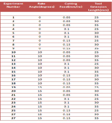
A. Plan of Experiments
Taguchi‘s parameter design is an important tool for robust design, which offers a simple and systematic approach to optimize a design for performance, quality and cost. Taguchi‘s
[image:2.595.316.543.61.310.2]
Table 1 Process parameters and their levels
full factorial design with three parameters each at three levels and L27 Orthogonal array (Table 2) was used for this
[image:2.595.29.290.509.637.2]experiment.
Table 2 L27 Orthogonal array
B. Work piece Material
AISI 1060 steel rod is used for machining. It has good machinability, and is the most commonly used material for dies and moulds. Initial work piece diameter is taken as 40 mm, and work piece length as 250 mm (approx.)
C. Tool material
AISI T-42 CT (Cryogenically Treated) H.S.S tools are used for turning operations. Cryogenic treatment is the supplementary process to conventional heat treatment process in H.S.S steels by deep freezing the material to improve the physical and mechanical properties of the material being treated [7]. Rohit EC 500 (T42-CT) single point cutting tool bits used in this work were purchased from their dealers. Chemical composition and properties of T-42 CT H.S.S materials are shown in Table 3
Table 3 Chemical composition and properties of T-42 H.S.S tool material
D. Tool and cutter grinder
The purchased T-42 CT H.S.S single point tool bits (12 × 12 × 100 mm) were ground to required tool geometry using BMT-TCG 1 tool and cutter grinding machine. The tools with rake angles of 0°, 10°, 15° were used for turning operation. Process Parameters Designation Level-1 Level-2 Level-3
Rake angle (degree)
A 0 10 15
Feed (mm/rev)
B 0.05 0.1 0.15
Tool extension length(mm)
[image:2.595.306.554.532.686.2]www.ijsrp.org Same clearance angle of 12° and side and end cutting anglesof
10° were selected for all the tools with different rake angles.
E. Centre lathe
[image:3.595.318.556.63.189.2]All the 27 experiments were carried out on the precision centre lathe, NAGMATI-175 (Fig. 2) which enables high precision machining and production of jobs. Technical specifications of Centre lathe are, Centre height: 175 mm, Power required: 2.25 KW, Swing over bed: 350 mm. Cutting speed (50 m /min) and depth of cut (1mm) are kept constant throughout the experiments. Before taking the readings, the system was run idle for 30 minutes so that a steady state was reached.
Fig 2 NAGMATI-175 Centre lathe
F. Lathe tool force dynamometer
The instrument used for cutting force measurement was Sharp UIL-15 multi component force indicator. It comprises of three independent digital display calibrated to display force directly using three component tool force dynamometer. Instrument operates on 230 V, 50 Hz AC mains.
III. FINITEELEMENTANALYSIS
Parallel to the development in computer technology, finite element method (FEM), one of the most accurate numerical solution methods, has been increasingly used for modelling cutting operations [3-6]. It gives accurate results and therefore, it is now a well-accepted numerical method.
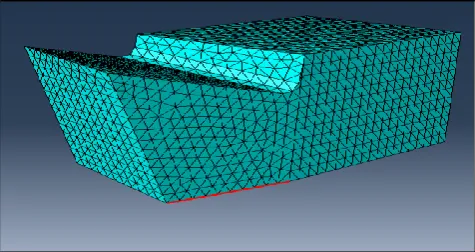
Cutting tools were modeled using Autodesk Inventor-2011 as a solid model and deflection of cutting tools under cutting forces are analysed using ABAQUS/CAE 6.10, finite element program. The created solid model was saved as IGES format and imported to ABAQUS and divided into finite elements.
Fig 3 T42 H.S.S CT cutting tool model after meshing (rake angle 15°)
Boundary conditions were applied by fixing one end of the beam and cutting forces were applied on the cutting edge as uniform loads along X, Y, Z directions. The cutting tool material was regarded as having linear elastic isotropic properties and its values were entered through material properties icon. C3D4, 3 dimensional 4 node tetrahedron structural solid element with linear displacement behaviour was used as the element type. A mesh sensitivity study was conducted before selecting the final mesh and element size. A uniform mesh was used throughout the length of cutting tool. A total number of 28000 elements (approx.) have been created in a typical tool model (Fig. 3).
IV. RESULTSANDDISCUSSION
G. Influence of tool rake angle on cutting force components
Fig. 4 shows the variation of cutting force components with changes in rake angle. The results are shown for a tool extension length of 25 mm and feed of 0.05 mm/rev.
In general, these results show that all the components of cutting force decrease with increase in rake angle. Further while the reduction in the magnitudes of force with rake angle is significant for cutting force (FS) and feed force (FV), it is less
pronounced in the case of radial force (FP). This decrease in
cutting forces is attributed to the decrease in tool/chip contact area and friction force, so that chip will be formed easily [8, 9].
Fig 4 Rake angle effect on cutting forces
H. Influence of cutting feed on cutting force components
[image:3.595.303.559.530.667.2]www.ijsrp.org Fig 5 Influence of cutting feed on cutting forces
The results show that three components of force i.e. FS, FV, FP increase as the cutting feed increases in T42 H.S.S
single point cutting tools. Further, the above increase is more pronounced for 0° rake angled tool compared to that for 15° rake angled tool.
I. Influence of tool extension length on cutting force components
[image:4.595.321.555.61.299.2]The variation of the cutting force components with tool extension length for 0° and 15° rake angled tools are shown in Fig. 6.
It may be observed from the results that all the component forces decreases slightly with increase in tool extension length. When extension length increases forces applied by work piece on cutting tool decreases and reaction forces i.e. cutting forces also decrease. Cutting force variation is very narrow for feed force (FV) and radial force (FP) as compared to main cutting
[image:4.595.37.271.65.201.2]force (FS).
Fig 6 Effect of tool extension length on cutting forces
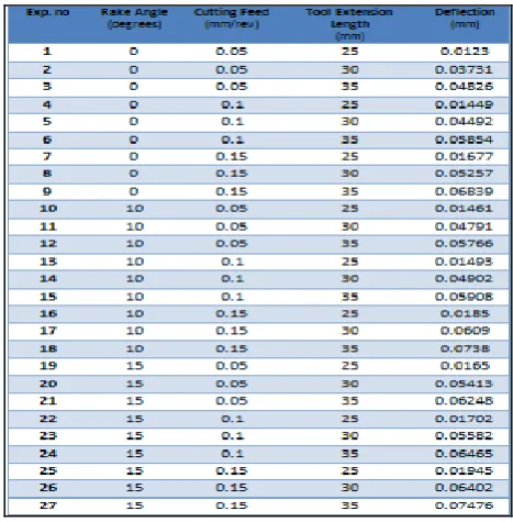
J. Deflection analysis
The deflection values found out by using finite element method are shown in Table 4. It is clear from the results that deflection values increase as cutting feed, tool extension length and cutting feed increases. All the values of deflection obtained were less than 0.1mm, the permitted value in rough turning operation. Whereas, only 14 experiments (Ex No 1, 2, 3, 4, 5, 7, 10, 11, 13, 14, 16, 19, 22, 25 ) can be recommended for finishing operation, since their deflection values are below 0.05 mm.
Table 4 Deflection values obtained by FEM
Fig 7 shows the differences between deflection values obtained by beam equation and finite element program, ABAQUS.
Fig 7 Comparison of deflection values
The difference between deflection values is lower at zero rake angle, but it becomes significant as rake angle increases. This is due to the reason that, when we find out the deflection using beams equation, cross section of beam is considered as uniform throughout the length i.e. no consideration is given to the tool geometry. Also deflection is calculated by applying cutting force (FS) at its free end as a point load. Whereas other
two components FP and FV were neglected due to its low
magnitude as compared to main cutting force FS.
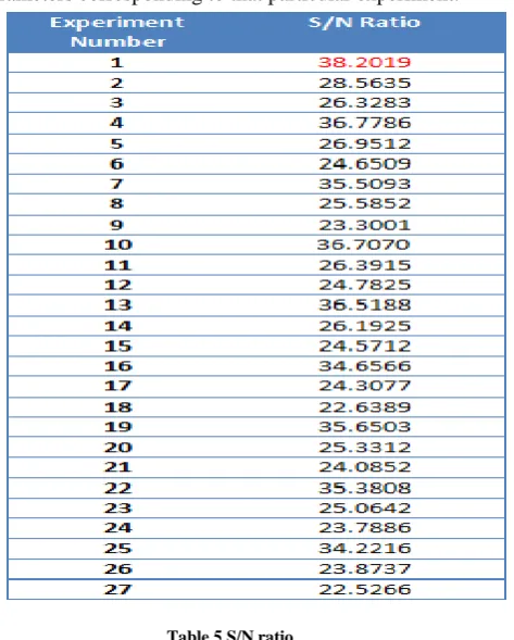
K. Analysis of S/N ratio
[image:4.595.312.556.375.529.2] [image:4.595.38.284.442.580.2]www.ijsrp.org Signal to Noise ratio is found out in each case using the
criteria ‗lower is better‘ as deflection is the factor of consideration. The S/N ratio for ‗lower is better‘ is
where, n is the number of measurements in a trial/row (here n=1) and y is the measured value in a run/row. S/N values for the present study computed using the above equation are given in Table 5. Regardless of the category of the performance characteristics, a greater S/N ratio corresponds to a better performance. Therefore, the optimal level of the machining parameters is the level with the greatest S/N value. From this table it is clear that greatest S/N ratio occurs at experiment number 1. It means that the deflection will be minimum for the parameters corresponding to that particular experiment.
Table 5 S/N ratio
[image:5.595.313.550.130.290.2]In order to determine the most significant level as well as parameters, the average deflection values for all the parameters corresponding to different levels are found out and shown in Table 6.
Level Rake Angle Cutting Feed Tool Extension Length
1 0.04174 0.03971 0.01606
2 0.04405 0.04288 0.05184
3 0.04765 0.05085 0.06553
Delta 0.00591 0.01114 0.04946
[image:5.595.46.283.248.543.2]Rank 3 2 1
Table 6 Average deflection values in each level
From the above table it is clear that all the deflection values are minimum at level 1 (i.e. with rake angle 0o, cutting feed 0.05 mm/rev and tool extension length 25mm). Further, the tool extension length parameter which is ranked as 1, becomes the most significant factor affecting the deflection.
Fig 8 Response graph of the mean deflection
Also, the response graphs of the mean deflection corresponding to the data presented in Table 6 are shown in Fig. 8. The graph clearly demonstrates the importance of tool extension length on deflection as compared to other parameters.
L. Regression analysis
The correlation connecting different factors (cutting feed, rake angle, tool extension length) with deflection of T42 CT H.S.S single point cutting tool were obtained by multiple linear regression equation. The equation is in the form
Deflection = - 0.113 + 0.000546 A + 0.109 B + 0.00470 C
and R2 = 0.90
where, A=rake angle, B=cutting feed, C= tool extension length. Here R2 is the regression coefficient (R2=0.90) for the models, which indicate that the fit of the experimental data is satisfactory [11].
M.Analysis of Variance
ANOVA is a statistics based, objective decision making tool used to investigate the significance of each factors on entire process. This analysis was carried out for a level of significance of 5%. Table 7 shows the result of ANOVA.
Parameter DOF SS MS F P P (%)
Rake Angle 2 0.0003169 0.0001584 12.37 0.000 2.64
Cutting Feed 2 0.0005684 0.0002842 22.18 0.000 4.74
Tool
Extension Length
2 0.0108474 0.0054237 423.35 0.000 90.48
Error 20 0.0002562 0.0000128 2.14
Total 26 0.0119889 100
[image:5.595.40.284.603.743.2] [image:5.595.306.559.608.766.2]
www.ijsrp.org It can be observed from the above table that the percentage
influence of tool extension length, cutting feed and rake angle on the deflection of T-42 CT H.S.S single point cutting tool are 90.48 %, 4.74 % and 2.64 % respectively.
V. CONFORMATION OF EXPERIMENT
The conformation test is the final step in verifying the results drawn based on Taguchi‘s design approach. To validate the optimum deflection values a conformation test was done by utilising the levels of optimal process parameters (rake Angle = 0°, cutting feed = 0.05 mm/rev, tool extension length = 25 mm). Confirmation experiment yields a deflection of 0.012 mm, whereas the result obtained using regression modelling equation is 0.011mm, which ascertains the accuracy of the predicted equation.
VI. CONCLUSIONS
This paper attempts to conduct a detailed FEM analysis of deflection of T-42 CT H.S.S tools using cutting forces measured by a lathe tool force dynamometer and study the effect of input parameters on cutting forces and deflection. It also formulates an empirical relationship between the deflection values and the input parameters. Based on the analytical and experimental results obtained in this study following conclusions can be drawn.
1. As rake angle and tool extension length increases, all the components of cutting force decreases. Whereas with increase in cutting feed, the cutting force increases. 2. Deflection of cutting tool increases with increase in
rake angle, cutting feed and tool extension length. 3. Percentage influence of tool extension length, cutting
feed and rake angle on the deflection of T-42 CT H.S.S single point cutting tool is 90.48 %, 4.74 % and 2.64 % respectively.
4. All the components of cutting force slightly decrease with tool extension length. Whereas, tool extension length significantly influences the deflection.
5. Empirical equation relating various process parameters and deflection is formulated.
6. Optimum values of rake angle (0°), cutting feed (0.05 mm/rev) and tool extension length (25 mm) which give minimum deflection are found out using Taguchi optimization technique.
ACKNOLWLEDGEMENT
Authors are thankful to the Department of Production Engineering, Vidya Academy of Science and Technology, Thalakkotukara, Thrissur, Kerala for providing the facility for conducting experiments.
REFERENCES
[1] Gaurav Bartarya, S.K choudhury, ―Efeect of cutting parameters on cutting force and surface finish hard turning AISI52 100 grade steel‖, Procedia CIRP 1, pp 651-656, 2012
[2] P.G Benardos, S. Mosialos,G.C Vosniakos, ―Prediction of Workpiece elastic Deflection under cutting forces in turning, Robotics and CIM,22, pp 505-514, 2006
[3] Abdullah Duran, Muammer Nalbant,‖Finite Element analysis of bending occurring while cutting with high speed steel lathe tools‖, Material design,26, pp-549-554, 2005
[4] ZhouJM,Anderson M, StahlJE, ―Cutting tool fracture and strength evaluation by stress identification‖, part 1, stress modal Int Mach Tools Manufact,pp 101-1714,1997
[5] Mankova I, Kovac,P, Kundark,‖Finite element analysis of hardened steel cutting‖,Journal of Production Engineering,14,pp 7-10,2010
[6] Chanrakanth Shet,Xiamin Deng,‖Finite element analysis of orthogonal metal cutting process‖. J. Materials processing technology,105, pp 95-109, 2000
[7] S Sendooran, P Raja,‖ Metallurgical investigation on cryogenic treated H.S.S tool,‖I. J Engineering science and technology, 3, pp 3992-3996, 2011 [8] Mustafa Gunay, Ihsan Korkut,―Experimental investigation of the effect of cutting tool rake angle on main cutting force‖,Jo Materials processing technology,166,pp 44-49, 2005
[9] Satyanarayana. Kosaraju,Venugopal. ―Effect of rake angle and feed rate on cutting forces in an orthogonal turning process‖, Int conference on trends in mechanical and industrial engineering ,Bangkok Dec,2011
[10] Sijo M.T and Biju N, ―Taguchi method for optimization of cutting parameters in Turning Operations‖ AMAE, 536,pp-103-105,2010
[11] Rama Rao S, Padmanabhan G, ―Application of Taguchi methods and ANNOVA in optimization of process parameters for metal removal rate in electrochemical machining of AL/5%SiC Composites‖,In J engineering research and application, 2,pp 192-197,2012
AUTHORS
First Author – Renjith V B, P G Scholar in Mechanical Engineering Department ( Production Engineering), Govt Engineering College, Thrissur Email: [email protected]
![Fig 1 Cutting forces acting on the cutting tool during turning [3]](https://thumb-us.123doks.com/thumbv2/123dok_us/9106374.984008/1.595.317.548.202.335/fig-cutting-forces-acting-cutting-tool-turning.webp)