eeeeeeeeeeeoeee80eeOeeGe80eeeeeeec
Reference Drawing
tollating List of Pages
This reference drawing contains the collating sequence, page side, and EC level of pages for IBM 3480 MagnetIc Tape Subsystem Maintenance Information Manual (MI) Volume A01, SY32-5048-13.
The part number of the divider tab list is 8673743.
This reference drawing is to be placed at the front of the manual.
PAGE SIDE LEVEL PAGE SIDE LEVEL PAGE SIDE LEVEL PAGE SIDE LEVEL
PLAN 45 Front EC A57693 START Tab CART 1 Front EC C13783
FRONT COVER Front EC C137B3 PLAN 46 Back EC 336396 CART 2 Back EC C13783
PREF 1 Back EC 336395 START 1 Front EC A57724
PLAN 50 Front EC 336395 START 2 Back EC 336396 CART 5 Front EC 336395
SAFETY 10 Front EC 336395 PLAN 51 Back EC 336395 CART 10 Back EC 336395
SAFETY 20 Back EC 336395 START 10 Front EC A57724
PLAN 55 Front EC A57723 START 100 Back EC A47957 CART 10-1 Front EC 336395
SAFETY 30 Front EC 336395 PLAN 60 Back EC 336396 CART 10-2 Back EC 336395
SAFETY 40 Back EC 336395 START 101 Front EC 336396
PLAN 65 Front EC 336395 START 105 Back EC A57723 CART 10-3 Front EC 336395
TAB 1 Front EC 336395 PLAN 70 Back EC A57723 CART 12 Back EC 336395
TAB 2 Back EC 336395 START 106 Front EC A57723
INTRO Tab START 110 Back EC A57723 CART 13 Front EC 336396
GLOSS Tab CART 14 Back EC 336396
INTRO 1 Front EC 336395 START 111 Front EC A57723
GLOSS 1 Front EC 336395 INTRO 5 Back EC A57723 START 115 Back EC 336396 CART 15 Front EC 336396
GLOSS 2 Back EC 336395 CART 16 Back EC 336396
INTRO 10 Front EC 336395 START 120 Front EC A57723
GLOSS 3 Front EC 336395 INTRO 15 Back EC 336395 START 125 Back EC A57723 CART 17 Front EC 336396
GLOSS 4 Back EC 336395 CART 20 Back EC 336396
INTRO 20 Front EC A57723 START 130 Front EC A57723
PLAN Tab INTRO 21 Back EC 336395 START 135 Back EC A57723 CART 21 Front EC 336395
CART 30 Back EC 336395
PLAN 1 Front EC A57723 INTRO 22 Front EC A57723 START 140 Front EC A57723
PLAN 5 Back EC A57723 INTRO 25 Back EC 336395 START 300 Back EC A57724 CART 40 Front EC A57723
CART 42 Back EC 336396
PLAN 6 Front EC 336396 INTRO 30 Front EC A57723 START 310 Front EC A57724
PLAN 10 Back EC 336396 INTRO 35 Back EC 336395 START 315 Back EC A57724 PNEU Tab
PLAN 11 Front EC 336395 INTRO 40 Front EC 336396 START 320 Front EC A57724 PNEU 1 Front EC 336395
PLAN 25 Back EC 336395 INTRO 45 Back EC 336396 START 325 Back EC A57724 PNEU 3 Back EC 336395
PLAN 30 Front EC A57723 INTRO 50 Front EC 336395 START 400 Front EC 336396 PNEU4 Front EC 336396
PLAN 35 Back EC A57723 INTRO 51 Back EC 336395 START 401 Back EC 336396 PNEU 5 Back EC
A5i693
PLAN 40 Front EC A57723 INTRO 55 Front EC A57723 START 420 Front EC 336396 PNEU 6 Front EC 336395
PLAN 41 Back EC 336395 INTRO 56 Back EC 336395 CART Tab PNEU10 Back EC 336395
PAGE
PNEU 11 PNEU12
PNEU 20 PNEU 30
PNEU 103 PNEU 105
PNEU 106 PNEU 110
PNEU 111 PNEU 112
PNEU 120 PNEU 130
PNEU 140 PNEU 150
MSG Tab
MSG 1 MSG 10
MSG 15 MSG 20
MSG 21 MSG 21-1
MSG22 MSG23
MSG 30 MSG 100
MSG 105 MSG 200
MSG 201 MSG 210
MSG 211 MSG 212
MSG 213 MSG 215
MSG 216
3480
MI SIDE Front Back Front Back Front Back Front Back Front Back Front Back Front Back Front Back Front Back Front Back Back Front Front Back Front Back Front Back Front Back Front Back Frontj
LEVEL
EC 336395 EC A57723
EC 336395 EC A57723
EC 336396 EC A57693
EC 336395 EC 336395
EC 336396 EC A57723
EC 336396 EC A57723
EC A57723 EC A57723
EC A57723 EC 336395
EC 336395 EC C13783
EC C13783 EC C13783
EC C13783 EC C13783
EC 336395 EC A57723
EC 336395 EC 336395
EC 336395 EC A57723
EC A57723 EC A57723
EC A57723 EC 336395
EC 336395
l
}
PAGE
MSG 220
MSG 221 MSG 222
MSG 223 MSG 225
MSG 226 MSG 228
MSG 229 MSG 230 MSG 231 MSG 350 MSG 360 MSG 361 MSG 411 MSG 412 INST Tab INST 1 INST2 INST4 INST 5 INST6 INST 10 INST 11 INST 13 INST 20 INST 21 INST 22 INST 30 INST 31 INST 40 INST 41 INST 45 INST 50 INST 55
)
SIDE Back Front Back Front Back Front Back Front Back Front Back Front Back Front Back Front Back Front Back Front Back Front Back Front Back Front Back Front Back Front Back Front BackLEVEL
EC A57723
EC A57723 EC A57723
EC A57723 EC A57723
EC A57723 EC A57721
EC A47957 EC 336395
EC 336395 EC 336395
EC 336395 EC A57723
EC A47957 EC 336395
EC 336396 EC A57721
EC A57723 EC 336396
EC 336396 EC A57723
EC A57693 EC 336396
EC A57723 EC 336396
EC A57723 EC A57723
EC A57723 EC A57724
EC A57721 EC A57721
EC 336396 EC 336396
)
\
)
~)
)
PAGE
INST 56 INST 60 INST 61 INST 70 INST 71 INST 72 INST 73 INST 74 INST 75 INST 76 INST 77 INST 78 INST 79 INST 81 INST 82 INST 83 INST 84 INST 90 INST 100 INST 110 INST 120 INST 130 INST 131 INST 135 INST 136 INST 137 INST 140 INST 150 INST 160 INST 170 INST 180 INST 190 INST 304 INST 305 SIDE Front Back Front Back Front Back Front-Back Front Back Front Back Front Back Front Back Front Back Front Back Front Back Front Back Front Back Front Back Front Back Front Back Front BackLEVEL
EC 336396 EC 336396
EC A57721 EC A57721
EC A57723 EC 336395
EC A57721 EC A57721
EC 336396 EC A57721
EC A57723 EC A57721
EC A57721 EC A57721
EC A57721 EC A57721
EC A57721 EC A57723
EC A47957 EC A57724
EC 336396 EC 336396
EC 336396 EC A57723
EC 336396 EC A57723
EC A57i21 EC A47957
EC 336396 EC
A5i721
EC 336396 EC A57723
EC A57723 EC 336395
~)
}
.
)
PAGE
INST 306 INST 310 INST 311 INST 313 INST 320 INST 321 INST 325 INST 330 INST 331 INST 340 INST 341 INST 345 INST 350 INST 355 INST 356 INST 360 INST 361 INST 370 INST 371 INST 372 INST 373 INST 374 INST 375 INST 376 INST 377 INST 378 INST 379 INST 381 INST 382 INST 383 INST 384 INST 390 INST 400 INST 410, 1
SIDE Front Back Front Back Front Back Front Back Front Back Front Back Front Back Front Back Front Back Front Back Front Back Front Back Front Back Front Back Front Back Front Back Front BackLEVEL
EC A47957 EC A57721
EC 336396 EC 336396
EC 336395 EC 336395
EC 336396 EC A57723
EC A57723 EC A57724
EC A57721 EC A57721
EC 336396 EC 336396
EC 336396 EC 336396
EC 336396 EC A57721
EC A57721 EC 336395
EC 336395 EC 336395
EC 336396 EC A57721
EC A57721 EC A57721
EC 336395 EC A57721
EC 336396 EC A57721
EC 336396 EC 336396
EC A47957 EC A57724
~)
Reference Drawing
A01-2
e
e e e
-
--
-
--
0
e
0
0
G
0
0
0 0
C)
0 0 0 0 0
G
--
0
e
0
0
e
e
e
0
()
Reference Drawing
PAGE SIDE LEVEL PAGE SIDE LEVEL PAGE SIDE LEVEL
INSP 41 Front EC 336395 INDEX 7 Front EC A57723
INST 420 Front EC 336396 INSP 45 Back EC 336395 INDEX 8 Back EC A57723
INST 430 Back EC 336396
INSP 55 Front EC 336395 INDEX 9 Front EC A57723
INST 431 Front EC 336395 INSP 56 Back EC A57721 INDEX 10 Back EC A57723
INST 435 Back EC 336395
INSP 58 Front EC 336396 INDEX 11 Front EC A57723
INST 436 Front EC 336395 INSP 60 Back EC 336396 INDEX 12 Back EC A57724
INST 437 Back EC 336395
INSP 65 Front EC 336396 INDEX 13 Front EC A57723
INST 440 Front EC A47957 INSP 70 Back EC 336396 INDEX 14 Back. EC A57723
INST 450 Back EC A47957
INSP 110 Front EC 336395 RCF-1 Front
INST 460 Front EC 336396 INSP 115 Back EC 336395 RCF-2 Back
INST 470 Back EC 336396
INSP 116 Front EC 336395
INST 480 Front EC 336395 INSP 120 Back EC 336395
INST 490 Back EC 336395
INSP 121 Front EC 336395
INST 495 Front EC 336396 INSP 124 Back EC 336395
INST 500 Back EC A57723
INSP 125 Front EC 336395
INST 502 Front EC 336396 INSP 132 Back EC 336395
INST 505 Back EC A57723
INSP 135 Front EC A47957
INST 507 Front EC 336396 INSP 140 Back EC A47957
INST 510 Back EC 336396
INSP 141 Front EC 336395
INST 515 Front EC A57723 INSP 145 Back EC 336395
INST 520 Back EC 336396
INSP 155 Front EC 336395
INSP Tab INSP 156 Back EC A57721
INSP 1 Front EC 336396 INSP 158 Front EC 336396
INSP 2 Back EC 336395 INSP 160 Back EC 336396
INSP 10 Front EC 336395 INSP 165 Front EC A47957
INSP 15 Back EC 336395 INSP 170 Back EC A47957
INSP i6 Front EC 336395
INSP 20 Back EC 336395 INDEX Tab
INSP 21 Front EC 336395 INDEX 1 Front EC A57723
INSP 24 Back EC 336395 INDEX 2 Back EC A57723
INSP 25 Front EC 336395 INDEX 3 Front EC A57723
INSP 32 Back EC 336396 INDEX 4 Back EC A57723
INSP 35 Front EC A57693 INDEX 5 Front EC A57723
INSP 40 Back EC A47957 INDEX 6 Back EC A57724
»
...,.~~•
m
8673861
~
to
CO
M
r--..
to
CO
PUBLICATIONS HEFEHENCE DRAWING
MACHINE TYPE/MODEL NO. 3400
MACHINE NAME - Magnetic Tape Subsyslem
FORM NO.
SY32-5048-0
S Y32-50-18-1
E C NO. 1 DESCHIPTION/COMMENTS
991552
336326
336389
VOL. /\01 - Maintenllnce Inforillolion
RE/\12-11603
TNL SN32-0301
IEC 0011225141 (HE/\ 12-25741.
R E /\12-1-1 651)
lEe 00212251-11 (HE/\12-11658,
RE/\12-25-196)
Second Edition
RE/\ 12-15334
IE C 00 11215 156
lEe 00'1'1225996
SY32-5048-2
I
336390
I
Third Edition
IEC 001122599"1
IEC 00-11215151
SY32-5048-3
I
336391
I
Fourth Edition
SY32-5048-4
1----S Y32-5048-5
._--_._-336392
336393
r~E/\
n-11223
IEC 0011215150
RE/\ 12-1'1922
RE/\12-15152
IEC 0011215159
IEC 0011225842
IEC 0011225843
Filth Edition
IE C 0011225998
IEC 00112281181
TNL SN32-5036
_ .. 1, ..
-336394
Sixth Edition
339394/\
1TNL SN32-5037
1---
---1---SY32-5040-6
336395
Sevellth Edition
IEC 0011225844
-._---." ---~.---.---.---.-.... _---_._-_ ... _--_. . ----_ .. -_ ... _---. ---._-....
__
._-._-_._---S Y32-5048-7
SY32-5048-8
SY32-5040-9
S Y32-5048-1O
S Y32-50-18-11
S Y32-5048-12
336396
Eighth Edition
IEC 0011222905
IEC 001'1222986
A47957C
1Ninth Edition
/\5""1693
Tenth Editioll
A57121
E leve nth Edition
/\57723
Twcllth Edition
1\57724
Thirteenth Edition
1---- --_._--. --_ ...•.. _---_ ..
__
. _-SY32-5048-13
C13703
Fourteellth Edition
IBid
DATE
CHANGE NO
--- ._---"-_ ..
_--.---.-.---.
-
-._
.._-".--DATE
~fi;
I
PUB REF DWG (PRO)
I
REL
1---
See
E~
History
A5Tt23
I1/24189
CHANGE' NO
DESIGNI
SHT
OF
I
5/11/9? - .
A57724 - :
I - - t - - - _ _ _ _
_
DETAIL
9/30/91
C13783
CHECK
CLASSIFICA TlON.... UST·
C~lN;;;-;;~:'
TO
r:tu;SP,_.~
I
D~VELOPMENT
NO
LOGIC PG NO
APPRO
R0001
co
en
-.J
VJ
CO
Ol
~OJ
~
!
---'--'--~----'--.--- -_ .... " ... -.-.y •
~
~ ~~.
...
""'"
"
...
...
....
~
'II <f!II
~
..
"""
-~
" . .",
~
, .. ,*,
...
" -U"
~ ~
,'*'
~
.. . <tIII
"""
'<t.".".~
.-."""
~
-•. ,"f/II/f~
" >tlffl
~
" " " ,
~
'L ,.!!If
~
~> • • , . " . "
~
>,.,,,",,
...-.
i'~"e e e e e o e o o e O O O O O C C C C O G O O O O G O O G G _ C G C
3480 Magnetic Tape Subsystem
--..-
--
---
-
-
~---
- .
----
---
---~-.-
Maintenance Information
3480
3480
S/N-
S/N-HI
HI
Haintenance
Haintenance
Information
Information
GLOSS
PWR
PLAN
SENSE
INTRa
PANEL
*START*
HO
CART
LOC
PNEU
CARR-CU
HSG
INST
INSP
INDEX
Vol AOI
Vol ADZ
Maintenance library
Maintenance Information
Logic Diagrams
3480
3480
3480
S/N-
S/N-
S/N-HI
HI
HI
Haintenance
Haintenance
Maintenance
Information
Information
Information
CARR-DR
LGND
FSI
SPROC
EAD
SDISK
DIAG
OF
OPER
Vol
A03
Vol A04
VolAOS
-Vats.
AD1
to
ADS
Vats.
CD1
and 001
Preface
This manual contains maintenance information about the IBM 3480 Magnetic Tape Subsystem and is intended for customer engineers responSible for servicing the 3480 tape subsystem. This publication is designed to be used with the IBM
Maintenance Device (MOl. Therefore, CEs using this manual should be familiar with that tool.
Prerequisite Knowledge
It is assumed that you have a background in data processing concepts and that you .. e familiar with the hexadecimal numbering system, stored program concepts, and have a basic understanding of tape subsystems and their relationship to a processor
I/O
channel. "',,. .3480 MI
EC336395
• ~ raM CoD. 1984. 1115. 1.88
\
}
,)
Related Publications
IBM Systsm/360 and Systsm/370 I/O Intsrfacs Channel to
Control Unit OrigiMl Equipment Mllnuiactll'flf'S'lnformlltion,
GA22-6974.
IBM 3480 MlIgNtic TII/HI Subsystem
Description,
GA32-0042.How to Update the Maintenance
Information
This manual
is
'form numberc:Ontrolhtd.
The
3480 manuals will . be updated by Technical Newsletters lTNUI. The TNL coverletter will indicate the new EC level. The entire manual will be updated by major revision.
AD
updates Me proc:esaed throughnormal MLC control. The Publications
Reference
Drawing (PRDI in the front of each volume contains the EC history.~
)
i)
~
)
\.
)
How to Order This Manual
This manual or pages can be ordered from one of the following: • United States
• Europe/Middle East/Asia IE/ME/A) • Americas/Far East (A/FE)
Use the wiring Diagram/logic Page Request form, Z150-0130. Be sure to include the form number of the manual when ordering the new manual or pages. Please write your telephone number on the form in case there .. e any questions repding your order.
United States
IBM Corporation . General Products Division Dept. 301..
Tucson,
Arizona 85744E/ME/A
International Business Machines SA.E., Division de Fabricacion Dept. 9290
Valencia, Spain
A/FE
IBM Argentina SA Dept. 020 H. Yrigoyen 2149
1640
Martinec, Pcia.
Buenos Aires
Republic of Argentina
~
}
t)
~)
Preface
PREF 1
Preface
PREF 1
"
.)
o
o
Safety
Rules for Safety
If (1) you know the safety rules for working with electrical and mechanical equipment and (2) you observe the rules, you can work safely with IBM equipment.
Do not fear electricity, but respect it.
While you are maintaining IBM equipment, (1) observe every safety precaution possible and (2) observe the following safety rules.
Work Environment
• Do not work alone in hazardous conditions or near equipment that has dangerous voltages. Always inform your manager if the conditions or voltages are a possible problem.
• Always look for possible hazards in your work environment. Examples of hazards are: moist floors, nongrounded extension cables, power surges, and missing safety grounds.
• Do not perform any action that makes the product unsafe or that causes hazards for the customer personnel.
• Before you start the equipment, ensure that other Service Representatives (SRs) and customer personnel, are not in a hazardous position.
• Do not wear loose clothing that can be trapped in the moving parts of a machine. Ensure that the sleeves of your clothing are fastened or are rolled above the elbow. If your hair is long, or if you wear a neck scarf, fasten it to make it safe.
• Insert your necktie into your clothing or fasten it with a clip (preferably nonconductive) at approximately 8 centimeters (3 inches) from its end.
• Lift the equipment or parts by standing or pushing up with your stronger leg muscles; this action removes the strain from the muscles in your back. Do not lift any equipment or parts that are too heavy for you.
• Put removed machine covers ina safe place while you are servicing the machine. Reinstall the covers before returning the machine to the customer.
• Always keep your Service Representative (SR) tool kit away from walk areas so that other persons cannot trip over it. For example, keep the kit under a desk or table.
• Observe good housekeeping practices in the area of the machines while you are performing maintenance and after completing it.
Trademark of the Gardner-Denver Co.
3480 MI EC336395
<I> Copyright IBM Corp. 1984, 1985
o
o
• After maintenance, reinstall all safety devices, such as guards, shields, labels, and ground wires. Exchange safety devices that are worn or defective. (Remember: the safety devices protect you from a hazard. You destroy their purpose if you do not reinstall them when you have completed the service call.)
Electrical Safety
• If possible, always unplug the power-supply cable before you work on a machine. When you switch off power at the wall box, lock the switch in the off position or attach a DO NOT OPERATE tag (Z229-0237) to the switch.
Note: A non-IBM attachment to an IBM machine may be powered from another source and may be controlled by a different switch or circuit breaker. • Switch off all power before (1) removing or assembling the
main units of the equipment, (2) working near to power supplies, (3) inspecting power supplies, or (4) installing changes in machine circuits.
• Unless the maintenance documents specifically instruct you, do not service the following parts with power on if the part
is removed from its installed position in the machine: power supplies, pumps, blowers, motor generators, and other units with voltages that are more than 30 V ac or 42.4 V dc. (This rule ensures that correct grounding is maintained.) • If you really need to work on equipment that has exposed
live electrical circuits, observe the following precautions: Ensure that another person, who is familiar with the power-off controls, is near you. Another person must be there to switch off the power, if necessary.
Do not wear jewelry, chains, metal-frame eyeglasses, or other personal metal objects. (Remember: if the metal touches the machine, the flow of current increases because the metal is a conductor.)
Use only insulated probe tips or extenders.
(Remember: worn or cracked insulation is unsafe.) Use only one hand while you are working on live equipment. Keep the other hand in your pocket or behind your back. (Remember: there must be a complete circuit for an electrical shock to occur. This precaution prevents your body from completing the circuit!)
When you use a tester, set its controls correctly and use insulated probes that have the correct electrical specification.
Do not touch objects that are grounded, such as metal floor strips, machine frames, or other conductors. Use suitable rubber mats obtained locally, if necessary.
o
o
• When you are working with machines having voltages more than 30 V ac or 42.4 V dc, observe the special safety instructions given in customer engineering memorandums (CEMs).
Never assume that power has been removed from a circuit. First, check that it has been removed.
• Do not touch live electrical circuits with the surface of a plastic dental mirror. (Remember: the surface of the dental mirror is conductive and can cause damage and personal injury.)
• If an electrical accident occurs:
1 . Use caution; do not be a victim yourself. 2. Switch off the power.
3. Instruct another person to get medical aid.
4. If the victim is not breathing, perform mouth-to-mouth rescue breathing. See "Electrical Accidents - First Aid"
(below).
Mechanical Safety
Do not touch moving mechanical parts when you are (1) lubricating a part, (2) checking for play, or (3) doing other similar work.
Safety Glasses
Wear safety glasses when:
Using a hammer to drive pins or similar parts Using a power drill
Using a spring hook to attach or remove a spring Soldering parts
• Cutting wire or removing steel bands
• Using solvents, chemicals, or cleaners to clean parts • Working in any other conditions that could injure your eyes
Tools, Testers, and Field-Use Materials
• Do not use tools and testers that have not been approved by IBM. Ensure that electrical hand tools, such as Wire-Wrap 1 tools and power drills, are inspected regularly.
• Exchange worn and broken tools and testers.
o
o
o
Safety
SAFETY 10
• Do not use solvents, cleaners, or oils that have not been approved by IBM.
Summary
Prevention is the main aid to electrical safety. Always think about electrical safety and use good practice, for example: • Ensure that the customer's power receptacle matches the
IBM equipment specifications.
• Inspect power cables and plugs; check for loose, damaged, or worn parts.
• Review the procedure in the maintenance documents before you remove a part that can hold an electrical charge from the machine. Carefully discharge the necessary parts exactly as instructed by the procedure.
• Do not use a normal light (for example, a table lamp) as an extension trouble light at a machine.
Never assume that a machine or a circuit is safe. No machine is
always completely safe. You may not know the exact condition of a machine because, for example:
• The power receptacles could be wrongly wired.
• Safety devices or features could be missing or defective. • The maintenance and/or changes history could be wrong or
not complete.
• The design could have a problem.
The machine could have damage, caused when it was shipped.
• The machine could have an unsafe change or attachment. • An engineering change or a sales change could be wrongly
installed.
• The machine could be deteriorated (1) because it is old or (2) because it operates in an extreme environment. • A part could be defective, therefore causing a hazard. • A part could be wrongly assembled.
These are some of the ways that the condition of the machine could affect safety. Before you start a service call or procedure,
have good judgment and use caution.
Safety
Electrical Accidents - First Aid
When performing rescue procedures for an electrical accident, do as follows:
• Use Caution: If the victim is still in contact with the
electrical-current source, remove the power; to do this, you may need to operate the room emergency power-off (EPO) switch or the disconnecting switch. If 'lou cannot find the switch, use a dry wooden rod or other nonconductive object to pull or push the victim away from contact with the electrical-current source.
• Work Quickly: If the victim is unconscious, he/she may
need (1) mouth-to-mouth rescue breathing and possibly (2) external cardiac compression if the heart is not beating.
• Call for the Rescue Service, such as the ambulance or the
hospital. Instruct another person to call for medical aid. Determine if the victim needs mouth-to-mouth rescue breathing. If he/she does, perform the following steps.
CAUTION
Use extreme care when you perform rescue breathing for a victim who may have breathed-in toxic fumes.
Do not
breathe-in air that the victim has breathed-out.
1. Prepare for rescue breathing:
a. Ensure that the victim's airway is open and that it is not obstructed; check the mouth for objects that may be obstructing the airway, such as chewing gum, food, dentures, or the tongue.
b. Place the victim on his/her back, put one hand behind the victim's neck, and put the other hand on his/her forehead.
c. Lift the neck with one hand, and tilt the head backward by pressing on the forehead with the other hand. See Figure 1.
3480 MI
EC336395
·~IBMCarp.1984.1i18&
..
\.
)
t)
Figure 1.
2. Look, listen, and feel to determine if the victim is breathing
freely:
a. Put your cheek near to the victim's mouth and nose. b. Listen and feel for the breathing-out of air. At the same
time, look at the victim's chest and upper abdomen to see if they move up and down.
3. If the victim is not breathing correctly:
a. Keep the victim's head tilted backward; (see Figure 1). Continue to press on the forehead with your hand; at the same time, rotate this same hand so that you can pinch together the victim's nostrils with your thumb and finger. See Figure 2.
Figure 2,
b. Open your mouth wide and take a deep breath. Make a tight seal with your mouth around the victim's mouth as shown in Figure 3 and blow into the victim's mouth.
Figure 3.
c. Remove your mouth to let the victim breathe-out, and check that the victim's chest moves down. See Figure
4.
d. Repeat steps band c once every 5 seconds either until the victim breathes for himself/herself or until medical aid comes.
o
u
Safety
SAFETY 20
Reporting Accidents
Report, to your field manager, all electrical accidents, possible electrical hazards, and accidents that nearly occurred.
(Remember: an accident that nearly occurs might be caused by a
design problem; your immediate reporting ensures that the problem will be solved quickly.)
Report also all small electrical shocks. (Remember: a condition that causes a small shock need only differ slightly to cause serious injury.)
Safety
SAFETY 20
,
[image:8.1232.296.1175.62.772.2]o
o
Safety
Danger Notices
A danger notice is used to notify the service representative that potentially lethal or extremely hazardous conditions exist. The danger safety notices and their page locations contained in this MI are shown below.
DANGER
Electric shock. The Drive Power switch
removes
dc voltages (bothac
and dc voltageson
tape units without8M 6460006)
to
that drive only, and does not affect the other drive in the tape unit.CARR-DR 8.
DANGER
Electric shock. Hazardous voltages are present
on
theac
power circuit breaker and the line cord.
CARR-DR 8.
DANGER
Electric shock. When setting the control unit
ac
power circuit breaker off, hazardous voltages are still presenton
the ac power circuit breaker and
on
theac
power line cord.CARR-CU 6.
3480 MI EC336395
<0 Copvroght IBM Co<p. 1984. 1985. 19H6
o
o
DANGER
Hazardous electrical voltages are present in the receptacle.
INST 6,306.
DANGER
Hazardous electrical voltages are present in the connector. Do not touch the outlet case with anything other than
test
probes until step 3 is completed.
INST 6,306.
DANGER
Electric shock. Hazardous voltages can
be
present in theac
line cord connectors.CARR-CU 1440, 1490.
DANGER
Hazardous electrical voltages are present. Do not touch the internal parts (pins and sockets) of the outlet until step 5 is completed.
INST 6,306.
o
o
DANGER
Hazardous electrical voltages are present. Do not touch the outlet before meeting the following requirements of steps 1 and 2.
INST 6,306.
DANGER
Hazardous voltages are present. If the measured voltage values are less than 1.0 V ac, you can touch the outlet. Avoid contact with the internal parts (pins and sockets) of the outlet.
INST 6,306.
DANGER
Dangerous voltages are present at the ac power cable socket. The safety cover must
be on
when the socket is not being used.INST 10,310.
CAUTION: TILT HAZARD
Do NOT open both drives of a tape unit that is not bolted to another tape unit or control unit. With the automatic cartridge feature installed and both drive drawers fully extended, a tape unit that is not bolted to another unit will tilt forward with about 20 Ibs. of force applied to the top of either automatic cartridge loader.
INST 4,11,20,135,180,304,311,320,435,480. INSP 15, 115.
o
o
o
Safety
SAFETY 30
DANGER
Make sure the circuit breaker that supplies power
to
the customer receptacle is off.If you are installing
a
Dual Control Unit subsystem, powerto
both customer receptacles mustbe
off.Make sure that there are
no
cables attachedto
the 110 tailgate assembly in the bottom rear of the control unit.INST 60, 360.
DANGER
Lethal voltages are present in the power servicing area. Safety is most important. Treat all circuits as live until measured.
Capacitors are possible exploding devices. Wear safety glasses when working in the power area. Always reinstall all safety covers before powering
on
the machine.PWR
130-1,400-1.DANGER High voltage.
PWR 400-7.
Notes
Notes
SAFETY 40
3480 MI EC336395
Notes
SAFETY 40
• COPYflght IBM Corp 1984. 198&
t)
1}
,
)
,)
\
~}
~}
~}
lJ
o
o
o
o
o
o
o
o
o
Tab List
Tab List
TAB 1
Volume A01
Volume A02
Volume A03
Volume A04
GLOSS Glossary
LGND Legend PWR Power Maps CARR-DR Drive Checks/ Adjustments/Removal/Replacement
PLAN Maintenance Plan SENSE Sense/Status
SPROC Support Procedures INTRO 3480 Introduction PANEL Panel
SDISK Support Diskette Procedures START Start Maintenance
DIAG Support Diagnostic Descriptions MD Maintenance Device
CART Cartridge Analysis
DF Data Fields and Registers LOC Locations
PNEU Pneumatic Analysis
MSG Console Messages and EREP
OPER Theory of Operation CARR-CU Control Unit
Checks/ Adjustments/Removal/Replacement INST Installation/Removal
INSP Safety Check Procedures INDEX Index
Volume A05
FSI Fault Symptom Index EAD Error Analysis Diagrams
3480 MI EC336395
Notes
Notes
TAB 2
3480 MI EC336395
Notes
TAB 2
It> Copyright IBM Corp. 1984. 1985. 1986
t)
~)
~l
l
}
~)
~}
;)
,
.J
, .
..1
J•
\o
o
Glossary and Abbreviations
This glossary defines the special terms, abbreviations, and acronyms that are used in this publication. It does not include all terms previously established for the IBM System/370 or its operating systems; therefore, if you do not find the term you are looking for, refer to the index or to the Vocabulary for Data Processing, Telecommunications, and Office Systems
GC20-1699.
This glossary includes definitions from:
The American National Dictionary for Information Processing, published by the Computer and Business
Equipment Manufacturers Association. This material is reproduced from the American National Dictionary for Information Processing, copyright 1977 by the Computer and Business Equipment Manufacturers Association, copies of which may be purchased from the American National Standards Institute, 1430 Broadway, New York, New York
10018. These definitions are identified by an asterisk (*).
The ISO Vocabulary of Data Processing, developed by the
International Standards Organization, Technical Committee 97, Subcommittee 1. Definitions from published sections of this vocabulary are identified by the symbol "OSO)"
preceding the definition. Definitions from draft proposals and working papers under development by the ISO/TC97 vocabulary subcommittee are identified by the symbol "(TC97)," indicating that final agreement has not yet been reached among its participating members.
access method. A technique for moving data between processor storage and input/output devices.
adj. Adjustment.
ALD. Automated logic diagram. allocation. See resource allocation. alter. To change.
amplifier. A device whose output is an enlarged reproduction of its input.
analog. Pertaining to data in the form of continuous variables, which are related to measurable physical quantities.
assignment. The naming of a specific device to perform a function.
assistance. Aid.
asynchronous. Without regular time relationship; unexpected or unpredictable with respect to the execution of a program's instructions.
att. Attachment. B/M. Bill of material.
3480 MI EC336395
{: CnpYf'qhl ,8M Coro 1984 19Mf)
o
o
backhitch. A slight motion in the backward direction just before moving tape in a forward direction.
back
u".
To go back to a recovery point for retransmission. BCC. Buffer channel command register.BCPC. Buffer channel pad counter register. BCPH. Buffer channel pointer high register. BCPL. Buffer channel pointer low register. BCR. Buffer channel remainder register. BCSE. Buffer channel status/error register. BCSH. Buffer channel stop high register. BCSL. Buffer channel stop low register. BCSS. Buffer channel storage sars register. BOAT. Buffer data not real register. BDC. Buffer device command register. BDGO. Buffer diagnostic 0 register. BDG1. Buffer diagnostic 1 register. BDPH. Buffer device pointer high register. BDPL. Buffer device pointer low register. BDR. Buffer device remainder register. BOSE. Buffer device status/error register. BOSS. Buffer device storage sars register.
beginning of tape (BOT). The location on a magnetic tape that indicates the beginning of the permissible recording area. bfr. Buffer.
bill of material. A list of part numbers. BM. Bill of material.
BMR. Buffer mode register. BOB. Beginning of block. BOC. Bus-out check. BOR. Beginning of record. BOT. Beginning of tape. bpi. Bits per inch.
o
o
BSB. Backspace block. BSF. Backspace file.
buffer. * A routine or storage used to compensate for a difference in rate of flow of data, or time of occurrence of events, when transferring data from one device to another. BWRP. Buffer wrap register.
CA. Channel adapter.
card extractor. A service representative tool. CARR. Checks-Adjustments-Removal-Replacement. CART. Cartridge Analysis.
CAUTION (Notice!. A word to call attention to possible personal harm to people. Contrast with DANGER. CB. Circuit breaker.
centimeter. One hundredth of a meter. See meter. CC. Condition code.
CCA. Channel card address register. CCB. Communication control block. CCC. Channel card control register. CCR. Channel command retry. ccw. Counterclockwise. CCW. Channel command word.
CCW chain. A list of channel command words to be performed in sequence.
CDR. Channel data register.
CDTI. Channel diagnostic tag-in register. CER. Channel error register.
channel command. An instruction that directs a data channel, control unit, or device to perform an operation or set of
operations. char. Character.
checklist. A list of items to be checked. CHK. Check.
CHL. Channel.
o
o
Glossary and Abbreviations
GLOSS
CHPID. Channel path identification. clk. Clock.
cm. Centimeter. CMD. Command.
CMR. Channel modifier register.
command. A control signal that initiates an action or the beginning of a sequence of actions.
condition code. A code that reflects the result of an input/output, arithmetic, or logical operation.
contaminant. Something that contaminates.
1
contingent connection. A connection between a channel path and a drive caused when a unit check occurs during an I/O operation.
control unit. A device that controls input/output operations of one or more devices.
CP. Circuit protector.
CPS. Cycles per second. See Hz. CRC. Cyclic redundancy check. CS. Control storage.
CRR. Channel request register. CST. Command status table. CSW. Channel status word. CTO. Channel tag out. ctr. Counter.
ctrl. Control. CU. Control unit.
CUA. Channel unit address. CUT. Control unit operations table.
DANGER (Notice). A word to call attention to possible lethal harm to people. Contrast with CAUTION.
data. * Any representations such as characters or analog quantities to which meaning is, or might be, assigned.
data buffer. The storage buffer in the control unit. This buffer is used to increase the data transfer rate between the control unit and the channel.
Glossary and Abbreviations
data check. A synchronous or asynchronous indication of a condition caused by invalid data or incorrect positioning of data. Some data checks can be suppressed.
OBI. Data buffer in. DBO. Data buffer out. dc. Direct current. DCB. Data control block. DCK. Data check.
OCR. Device control register.
DDR. Dynamic device reconfiguration. DE. device end.
degauss. To demagnetize an object.
degradation. A decrease in quality of output or throughput, or increase in machine error rate.
degraded. Decreased in quality of output or throughput or increased machine error rate.
demark. Mark to show that the buffer segment is not usable. designed. Has as a purpose.
detent. A mechanical device for holding moving parts in position.
detented. Held in position by a detent. DEV. Device.
OF. Data Fields and Registers.
DGHELO. Diagnostic hardware error log. DGOVL Y. Diagnostic overlay log. DIAG. Diagnostic.
DIDO. Data in data out bus. DIR. Device interrupt register.
direct access storage. (1) * A storage device in which the access time is in effect independent of the location of the data. (2) (TC97) A storage device that provides direct access to data. (2) See also immediate access storage.
directories. Data sets at the beginning of the MD diskettes that contain the names and locations of the other data sets on the diskette.
DLR. Device level register.
3480 MI
EC336395
~ CopyrIght IBM Corp. 1984, 1985
.'
, "\'\
,
\~J, )
DOT. Device operation table.
Double-stick cellophane tape.. Cellophane tape that has adhesive on both sides of the tape.
drive, magnetic tape. (ISO) A mechanism for moving magnetic tape and controlling its movement.
DSC. Device secondary clock register. DSE. Data security erase.
DSE (register). Device status and error register. DSH. Control unit serial high register.
OSlo Control unit serial low register. DSR. Device secondary register. DTR. Device tag register. EAD. Error Analysis Diagrams.
EBCDIC. Extended binary-coded decimal interchange code. EC. Edge connector. Engineering change.
ECA. Engineering change activity. ECC. Error correction code. elsewhere. To or at another place.
end of block (EOB). A code that marks the end of a block of data.
end of file (EOF). A code that marks the end of a file of data. end of tape (EOT). The end of the recording area on a tape. EOB. End of block.
EOF. End of file. EOJ. End of job. EOR. End of record. EOT. End of tape.
EPO. Emergency power off. EQC. Equipment check. EQU. Equate.
equipment check. An asynchronous indication of a malfunction.
:J
~)
ERA. Error register A register. ERB. Error register B register.
EREP. Environmental recording, editing, and printing. ERG. Erase gap.
ERPA. Error recovery procedure action. E / ME / A. Europe/Middle East/Asia.
exchange. ( 1) The act of removing an old or imperfect part and installing a new or perfect part. (2) Contrast with "swap." explosive. Can explode or cause to explode.
F. Fuse.
fault symptom code (FSC). A hexadecimal code generated by the drive or control unit microcode in response to a detected subsystem error, This code is used as an MI entry point by the service representative.
FE. Field Engineering.
FEALD. Field Engineering automated logic diagram.
field replaceable unit (FRU). An assembly that is replaced in its entirety when anyone of its components fails,
FIFO. First in first out.
file. * (ISO) A set of related records, treated as a unit, for example, in stock control, a file could consist of a set of invoices.
file protection. Prevention of the destruction of data recorded on a volume by disabling the write head of a unit.
format. * (ISO) The arrangement or layout of data on a data medium.
FP. File protect.
frayed. Damaged as if by an abrasive substance. FRU. Field replaceable unit.
FSB. Forward space block. FSC. Fault symptom code. FSF. Forward space file. FSI. Fault symptom index.
FTSC. Field Technical Support Center.
functional. Of, connected with, or being a function.
u
~)
Glossary and Abbreviations
GLOSS 2
Functional microcode. Microcode that is resident in the machine during normal customer operation.
FVP. Functional verify program. gnd. Ground.
g. Gram.
hertz (Hz). Unit of frequency. One hertz equals one cycle per second.
hex. Hexadecimal.
host system. See host processor. HS. High speed.
HV. High voltage.
Hz. Hertz (cycles per second).
1/
O. Input/output. IBG. Interblock gap.10. Identification.
identifier. That difference by which one thing can be distinguished from another.
IML. Initial microprogram load.
immediate access storage. * A storage device whose access time is negligible in comparison with other operating times. inertia. Tendency to remain at rest or continue in the same direction.
initial microprogram load (lML). The action of loading a microprogram from an external storage to writable control storage.
INST. Installation.
inter block gap (lBG). (1) * An area on a data medium to indicate the end of a block or physical record. (2) (Te97) The space between two consecutive blocks on a data medium. interface. * A shared boundary. An interface might be a hardware cO'l1ponent to link two devices, or it migh[ be a portion of storage or registers accessed by two or more computer programs.
intervention required. Manual action is needed. INTLK. Interlock.
INTRO. Introduction. ips. inches per second.
Glossary and Abbreviations
GLOSS 2
"
}
o
o
Glossary and Abbreviations
irrecoverable error lnJ (1) (TC97) An error that makes recovery impossible without the use of recovery techniques external to the computer program or run. (2) In item (11. the recovery techniques would be external to those that are incorporated, not only within the program that failed but also within the system, and would include human action such as analysis by a program support representativp..
ITA. Interval timer A register. ITB. Interval timer B register. ITC. Interval timer C register. IMR. Interrupt mask register. JAL. Jump address low register. JAH. Jump address high register.
K. (1)
*
When referring to storage capacity, two to the tenth power; 1024 in decimal notation. (2) Kelvin.kb. Kilobyte; a unit of 1024 bytes.
land pattern. Wires and connections on or below the surface of a circuit board.
LO. Load.
LED. Light-emitting diode. LGNO. Legend.
load point. See beginning of tape. LOC. Locations.
locate block. A subsystem operation in which a tape is moved so that a specific block is available for processing.
LRC. Longitudinal redundancy check. LSB. Least-significant bit.
LSI. Large scale integration technology. LSP. Local storage page register. LSR. Local storage register. LWR. Loop write-to-read. m. Meter.
MIT. Multiple track.
magnetic recording.
*
(ISO) A technique of storing data by selectively magnetizing portions of a magnetizable material.3480 MI EC336395
'( Copyrtght IBM Corl" 1 984 1985
o
o
magnetic tape. (TC97) A tape with a magnetizable surface layer on which data can be stored by magnetic recording. maintonance agreement. A contract between IBM and a customer for supplying service to the customer.
maintenance package. The maintenance aids that IBM supplies for servicing the subsystem.
MAP. Maintenance analysis procedure. MAQ. Maintenance agreement qualification.
mask.
*
(ISO) (1) A pattern of characters that is used to control the retention or elimination of portions of another pattern of characters. (2) To use a pattern of characters to control the retention or elimination of portions of another pattern of characters.master file.
*
(ISO) A file that is used as an authority in a given job and that is relatively permanent, even though its contents may change. Synonymous with main file. MCR. Maintenance control register.MD. Maintenance device. Microcode diagrams. MOA. Maintenance device adapter.
MOD. Maintenance device display. MOL Maintenance data in register. MOO. Maintenance data out register.
media capacity. The amount of data that can be contained on a storage medium, such as tape, expressed in bytes of data. meter (m). A unit of measure equal to 0.9144 yard. MICR. Micro instruction register.
micro. One millionth of. MICRO. Microcode.
microcode. ( 1) One or more micro instructions. (2) A code, representing the instructions of an instruction set, implemented in a part of storage that is not program-addressable. (2) To design, write, and test one or more micro instructions. (3) See also microprogram.
microdiagnostic routine. A program that runs under the control of a supervisor, usually to isolate field-replaceable units. microdiagnostic utility. A program that is run by the service representative to test the machine.
micro instruction. A basic or elementary machine instruction.
o
o
microprogram. • (1) (ISO) A sequence of elementary instructions that corresponds to a specific computer operation, that is maintained in special storage, and whose execution is started by the introduction of a computer instruction into an instruction register of a computer. (2) A group of micro instructions that, when executed, performs a preplanned function.
Note: The term microprogram represents a dynamic arrangement or selection of one or more groups of micro instructions for execution in order to perform a particular function. The term microcode represents micro
instructions used in a product as an alternative to "'hard-wired" circuitry to implement certain functions of a processor or other system component.
microprogram load. See initial microprogram load. milli. One thousandth of.
millimeter. One thousandth part of a meter. MI. Maintenance information.
MLC. Machine level control. mm. Millimeter.
modifier. That which changes the meaning. M P . Microprocessor.
MPL. Microprogram load. ms. Millisecond.
MSB. Most-significant bit. MSG. Message.
MTE. Multiple track error. MTI. Maintenance tag in register. MTO. Maintenance tag out register.
multi path. Pertaining to using more than one path. nano. One billionth part of.
N
I
A. Not applicable.net wire list. A list that shows the wiring connections for the logic boards.
net. Network.
network. The interconnection of electrical components. NOP. No operation.
o
o
Glossary and Abbreviations
GLOSS 3
NRZI. Non-return-to-zero change-on-ones recording. ns. Nanosecond.
OBR. Outboard recorder.
offline. (TC97) Pertaining to the operation of a functional unit without the continual control of a computer. Contrast with online.
OL T. Online test.
online. (TC97) Pertaining to the operation of a functional unit that is under the continual control of a computer. Contrast with offline.
OP. Operator panel. OPER. Operation. osc. Oscillator.
oscillator. A device that periodically varies a voltage. OSU panel. Operator setup panel.
outstanding. Waiting for processing. ov. Over voltage.
overrun. Loss of data because a receiving device is unable to accept data at the rate it is transmitted.
owner. One who owns something.
parameter.
*
(ISO) A variable that is given a constant value for a specified application and that may denote the application. part. Part number.p bit. Parity bit. PC. Parity check.
PCR. Processor control register. POR. Processor diagnostic register. PE. Parity error.
PER. Processor error register. PG. Parity generator. pgm. Program.
PGIO. Path group identification. PGM (map). Path group map. PGT. Path group 10 table.
Glossary and Abbreviations
PLAN. Maintenance Plan. PM. Preventive maintenance. PNEU. Pneumatics.
pneumatic. The parts of the subsystem that control the pressurized air and vacuum.
POR. Power-on reset.
primed. Pertaining to a condition of a tape drive when the controlling computer has addressed the drive but the drive was not in a ready state.
PS. Power supply.
PSR. Processor status register. Program support representative.
PST. Product support trained. PT. Product trained.
PWR. Power. R/W. Read/write.
RAM. Random access memory.
Random access memory. See direct access storage. RCR. Read control register.
RD. Read.
ROB. Read backward.
ROC. Read diagnostic control register. ROF. Read forward.
RECl. Record length.
reconnect. To physically or electrically put back together. record.
*
(ISO) A collection of related data or words, treated as a unit; for example, in stock control, each invoice could constitute one record.recording density. The number of bits in a single linear track measured per unit of length of the recording medium.
recoverable error. (1) An error condition that permits continued execution of a program. (2) Contrast with .. irrecoverable error."
ref. Reference. reg. Register.
3480 MI EC336395
~ COPVrlght IBM Corp. 19B4. 19B5
\
•
J
i
1
~;.J
reinstall. To put back the original part that was removed. remove. To take a part off of the machine.
RER. Read error register.
resource allocation. (ISO) The assignment of the facilities of a data processing system for the accomplishment of jobs. resume. To continue.
retry. To attempt again. REW. Rewind.
ROS. Read-only storage. RPM. Revolutions per minute. RPR. Read pattern register. RRC. Read residual count register. RSR. Read status register. RUN. Rewind-unload.
SAR. Storage address register. SB. Sense byte.
SCR. Silicon-controlled rectifier.
SOR. Statistical data recorder. Storage data register. s. Second(s) of time.
saturate. To completely fill. sel. Select.
segment. A part.
SEROES. Serializer/deserializer.
serialize. To change from parallel-by-byte to serial-by-bit. serializer. (ISO) A device that converts a space distribution of simultaneous states representing data into a corresponding time sequence of states.
SM. Service ~v1emorandum. SR. Service Representative.
servo [n.]. servos. An adjectival noun for use in qualifying some part or aspect of a servomechanism.
servomechanism [ n l * A feedback control system in which at least one of the system signals represents mechanical motion.
,
\
~)
, )
-"f,special feature. A feature that can be ordered to enhance the capability, storage capacity, or performance of an IBM product. but is not essential for its basic work.
SIO. Start I/O.
SNERRH. Sense error history table. SNS. Sense.
SS. Status store. ST. Store.
standard feature. The significant design elements of an IBM product that are included as part of the fundamental product. ST ART. Start maintenance.
Stoplock. A position-hold mode used when the tape is in a stopped position and under tension.
subsystem. A secondary or subordinate system, usually capable of operating independently of, or asynchronously with, a controlling system.
SUPP. Support.
swap. ( 1 ) The act of interchanging two identical field-replaceable units Within the same machine for test purposes. (2) Contrast with "exchange."
sync. Synchronous. synchronize.
synchronous. (1) (ISO) Pertaining to two or more processes that depend upon the happening of specific events such as common timing signals. (2) Occurring with a regular or predictable time relationship.
tach. Tachometer.
tachometer. A device that emits pulses that are used to measure/check speed or distance.
tailored. Changed to meet individual specifications.
tape cartridge. A container holding magnetic tape that can be processed without separating it from the container.
tape void. An area in the tape in which no signal can be detected; may be caused by a machine failure.
TB. Terminal board. TCC. Top-card connector.
tension [ n l (1) The force tending to produce elongation. (2) The condition of being stretched.
thread / load operation. A procedure that places tape along the tape path.
J
'\)
Glossary and Abbreviations
GLOSS 4
TI. Tape Indicate. TIE. Track in error. TM. Tapemark. tp. Test point. TU. Tape Unit. TUBI. Tape unit bus-in. TUBO. Tape unit bus-out. UEPO. Unit emergency power off.
unload. Prepare the tape cartridge for removal from the drive. and so on.
utilities. Utility programs.
Utility programs.. (1) * (ISO) A computer program in general support of the processes of a computer; for instance, a diagnostic program. (2) a program that enables the service representative to maintain (or prepare to maintain) data or other programs.
uv. Under voltage.
VES. Volume error statistics.
volume. (ISO) A certain portion of data, together with its data carrier, that can be handled conveniently as a unit.
VOM. Volt ohmmeter.
VRC. Vertical redundancy check.
WARNING (Notice). A word to call attention to possible damage to a program, device, or system. Contrast with CAUTION.
WCR. Write control register.
word. (1) (ISO) A character string that is convenient for some purpose to consider as an entity. (2) In 3480 and System/7, 16 bits, or 2 bytes. (3) In System/360 and System/370, 32 bits, or 4 bytes.
WSE. Write status/error register. WRITE. Write command. WTM. Write tape mark. XR. External register.
XRA. External register address register.
Glossary and Abbreviations
GLOSS 4
3480 Maintenance Summary . . . 5
The Maintenance Device . . . .. 5
Special Tools and Test Equipment . . . 5
DC Test Tool . . . 5
Card Extractor . . . 5
Tape Removal Tool . . . 5
PressurelVacuum Gauge . . . 5
PressurelVacuum Kit . . . 5
Oscilloscope . . . 5
Integrated Logic Probe . . . 5
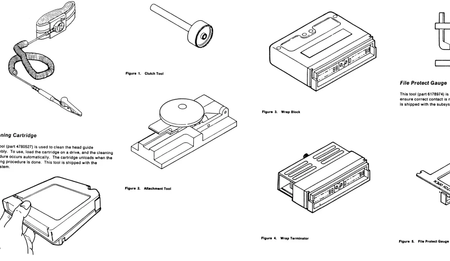
Cartridge Automation Facility Wrap Tool . . . 5
ESD Grounding Wrist Strap Tool . . . 6
Cleaning Cartridge . . . 6
Leader Block Replacement Kit . . . 6
Attachment Tool . . . 6
Clutch Tool . . . 6
Channel Wrap Blocks . . . 6
Hose Clamp Tool . . . 6
File Protect Gauge " . . . .. 6
Maintenance Information Description . . . 10
Volume A01--Maintenance Procedures . . . 10
GLOSS . . . 10
PLAN . . . 10
INTRO (Introduction) . . . 10
START . . . 10
CART (Cartridge) . . . 10
PNEU (Pneumatics) . . . 10
MSG (Message) . . . 10
INST (Installation/Removal) . . . 10
INSP (Safety Check Procedures) . . . 10
INDEX . . . 10
Volume A02--Maintenance Procedures and Control Unit 10 Checks, Adjustments, Removals and Replacements PWR (Power) . . . 10
SENSE . . . 10
PANEL . . . 10
MD (Maintenance Device) . . . . LOC (Locations) . . . . CARR-CU (Control Unit Checks, Adjustments, 10 10 Removals, and Replacements) . . . 10
Volume A03--Drive Checks, Adjustments, Removals, and Replacements . . . 10
CARR-DR (Drive Checks, Adjustments, Removals, and Repl acements) . . . 10
Volume A04--Support Procedures . . . 10
LGND (Legend) . . . 10
SPROC (Support Procedures) . . . 10
SDISK (Support Diskette Procedures) . . . 10
DIAG (Support Diagnostics) . . . 10
DF (Data Fields) . . . 11
OPER (Theory of Operation) . . . 11
Volume A05--Error Analysis Diagrams . . . 11
FSI (Fault Symptom Index) . . . 11
EAD (Error Analysis Diagrams) . . . 11
3480 MI EC A51723
Cl Copyrlg ht IBM Corp. 1982. 1899 3480 Maintenance Package Summary . . . 25Main Menu display . . . 30
3480 Product Support Summary . . . 50
Procedures . . . 55
Vary Offline . . . 55
How to Vary a Drive Offline (Single or Dual Subsystem) .. 55
How to Vary a Control Unit Offline (Single or Dual Control Unit Subsystem) . . . 55
Intermittent Failures . . . 55
End a Call . . . 60
Engineering Change . . . 60
Online Tests (OLTS) . . . 60
Section A: Control Unit Functional Test . . . 60
Section B: Pathing Commands Test . . . 60
Section C: ReadlWrite Reliability . . . 60
Section
0:
Tape Interchange . . . 60Integrated Logic Probe . . . 65
Sceping (Using Oscilloscope) . . . 65
Related Publications . . . 70
IBM Confldentlal - 15
May 89Contents
"AN 1
e
e
3480 Maintenance Summary
The 3480 maintenance p,ackage has two parts, the maintenance diskettes and the 3480 Maintenance Information manual.
The Maintenance Device
The maintenance device (MO) is the primary maintenance tool for the 3480 Magnetic Tape Subsystem.
The 3480 maintenance package supplies two diskettes for the MO, a product diskette and a suppqrt diskette. All 3480
maintenance analysis procedures (MAPs), except power MAPs, are resident on the prOduct diskette. In aadition, tlie product diskette contains utility programs. The support diskette contains diagnostics, subsystem display and alter controls, support utility programs, and microcode patch programs.
When the product diskette is inserted into the maintenance device, the maintenance device processes MAPs to analyze machine symptoms and display log data and to guide you to the failure. When necessary, y.ou enter symptom information on the MO keyboard/display as aClditional input to the MAPs.
Special Tools and Test Equipment
DC Test Tool
This tool (part 8492781) is shipped with the subsystem. Use this tool to determine if sUDsystem ~wer supplies are supplying output voltages. See PWR 10 or PWR 12 for a description of this tool and a description of how to use it.
, 2 3 4 5 8 7 8
DC Test Tool (part 8492781)
Card Extractor
This tool (part 1310707) is a site tool but must be obtained separately. It is used to remove logic cards from the subsystem. ThiS tool IS the same extractor tool as used on other IBM devices.
Card Extractor (part 1310707)
3480 MI EC A57723
Cl Copyright IBM Corp. 1982,1989
Tape Removal Tool
This tool (part 6850663) is shipped with the subsystem. Use it to rewind tape into the cartridge when the tape must be rewound by hand. See CART 12 for instructions on how to use the tape removal tool.
Tape Removal Tool (part 6850663)
Pressure/Vacuum Gauge
This tool (part 6850747) is used to measure the pneumatic system pressure or vacuum. See PNEU 5 for instructions on how to use the pressure/vacuum gauge.
PressureIVacuum Gauge (part 6850747)
Pressure/Vacuum Kit
(Part 6857823)
This kit contains hoses, fittings and the Pressure/Vacuum gauge (shown above) for measuring the P.J:leumatic system pressure or vacuum. This kit is not shipped With the subsystem and must be ordered.
Oscilloscope
The error analysis diagrams in the maintenance information manual instruct the service representative to use an
oscilloscope. A Tektronix' MOdel 453/454 or 475 or equivalent oscilloscope is needed.
"Trademark of Tektronix, Inc.
o
o
Integrated Logic Probe
The integrated logic probe (llP) (part 453222) can be used instead of an oscilloscope for all measurements except those that show timing between si~nals or the need to measure voltage values and tolerances. See 'Integrated logic Probe" in this section for instructions on how to use the probe.
For more instructions, see the Integrated Logic Probe Operators
Guide, S226-3951.
uo
....
-~'n
·"lDI
...
· .. ·0
-1J'fWi
IBM Confidential- 09 May 89
e
e
3480 Maintenance Summary
PLAN 5
Cartridge Automation Facility (CAF) WRAP Tool
The cartridge automation facility (CAF) wrap tool (part 39F3884) is used when runnin~ diagnostic E E 15 to veri fy the cartridge automation feature. "See DIAG "Cartridge Automation Facility WRAP test- Routine EE15" for more information on how to use this tool. This tool is shipped with the RPO.
Cartridge Automation Facility (CAF) WRAP Tool 1.14
!
i
3480 Maintenance Package Summary (Continued)
---~
1
1 Troutlle Call Information Source:
-1
System Console Error Message., - - - I Drive Message Display Check Msg .
I I Internal Subsystem error Logs.
I
All Maintenance action begins at the . Maintenance Information (M!) START section.I EREP Output.
I
1
AudiblelVisual Indications.I
1 Customer Description of Problem. 1y
START 1::1 defines problem eetermination and SR
I a::tlons to follow in the MI and MD Diskettes.
I 1 - - - -______________ 1
1 I
yl~
---
i---y~, ---~y
Failure
~
START Identifies those failures that do not reQuire the MD diskette, making reference to the MI sections to use, or defines actions to be performed before you use the MD Product Diskette.
y
MI procedures prior to use of MD Product Diskette. For repair follow MI pre-MD repair procedures.
I
y
Connect MD and IML Product Diskette. When main menu is displayed seiect START REPAIR.
...
Non-t.m repair procedures follow MI repair procedures until fixed.
I~
y
Connect MD and IML Product Diskette. When main menu is displayed,select UNIT TEST.
MD Product Diskette PLAN 35, 50
@
~y
~
I
I Main Menu Display
I
I
Option 2. Defer CallI
OptionI
Option 1. Start Repair 3. Unit TestG
CV
I
~
PLAN 40 PLAN 35 PLAN 35
Start Repair Defer Call Unit Test
3480 MI EC A57723
Cl Copyright/BN Co". 1182, 1 . . .
I
Subsystem Check Out Miscellaneous Procedures
START indicates MI sections that define non-repair procedures or provides supplemental Information to assist repair. Included are items such as: Predictive Maintenance; Operating tne Tape Drive; MD Use; Installation/Removal procedures; Analysis of sys~em console messages: EREP, Sense; Manual cartridge removal procedu~es.
~
~
MI sections for non-rep&ir procedures.I
MI sections for supplemental information.
,
Option 4. Display FRU
-
Option 5. UtilitiesFSC Error. Utilities
Key FSC into
Option 2. Real.
~ime
Analysisioption 3. Main Menu the MD and Option 1. Read Tapehit enter.
Note:
I
~
Use the product diskette. This gives a list of possible defective FRUs to exchange. This diskette can be run without the MD attached
I
to the Control Unit.
~
This Is • non-directed option that gives the This OPtion gives the service representative service representative the ability to read the ability to Enable or Disabl, Real Time customer tapes and display the first 80 Statistical Analysis and Reponing System.
cltafacter. of the record. on the MD.
·ttJ
NPLAN 45
Read Tlpe
IBM Confldentill- 31 May 89
•
It
3480 Maintenance Package Summary (Continued)
PLAN 30
,
,3480 Maintenance Package Summary (Continued)
PLAN 30
, > ~
34s.aintenance pa.ge Summary (8tntinUed)