© 2017, IRJET | Impact Factor value: 5.181 | ISO 9001:2008 Certified Journal | Page 2070
Comparative analysis fully developed turbulent flow in various
arbitrary cross-section ducts using Finite volume approach
Manish kumar
1, Dilbag Singh Mondloe
2, Satish Upadhyay
31
M.Tech Scholar, Government Engineering College, Jagdalpur
2
Assistant professor, Dept. of Mechanical Engineering, GEC Jagdalpur, Chhattisgarh, India
3Lecturer, Dept. of Mechanical Engineering, GEC Jagdalpur, Chhattisgarh, India
---***---Abstract -
In this paper, a three dimensional comparativeCFD analysis of an three arbitrary cross sectional pipe i.e. circular, triangular and rectangular pipe have been performed. While analysis the flow, all the three pipes have same cross sectional area so that the fully developed flow can be visualized. The partial differential governing equation i.e Naiver stokes equation has been solved by using computational FEV solver tool i.e. ANSYS Fluent. Through this investigation fully developed turbulent flow in arbitrary shaped pipe has been studied for higher Reynolds number. During analysis k-ε turbulence model has been selected and the flow of water within the pipe has been examined. Moreover, comparative flow analyses between the three pipes have been discussed in detail.
Key Words: Turbulent Flow, arbitrary cross sectional pipe
1. INTRODUCTION
The study of fluid flow in arbitrary shaped pipe and duct is very important because of its having wide applications in several industrial and engineering processes. Therefore, arbitrary shaped pipe have high significance in the area of heat transfer also. Consequently various research have been performed for estimation of convective heat transfer and fluid flow performance in the design of heat exchangers, solar air heat, refrigeration and also in some extent to industrial chillers. The arbitrary shaped pipe is also been referred as non circular pipe.
Talukdar et al. 2008 numerically replicated the forced and natural heat transfer in Laminar, Hydro-dynamically and thermally developed flow through triangular ducts under constant wall temperature and also analyzed along with the affect of apex angle on bulk mean temperature and Nusselt number.
Chiu et al. 2007 numerically examined the effect of radiation on convective heat transfer by solving Energy and Navier– Stokes equation using Vorticity and Velocity scheme, in horizontal and inclined rectangular 2008 cross-sectional duct.
Yan et al. 2001 numerically investigated the consequence of thermal radiations on convective heat transfer for a gray fluid through the vertical square duct by using vorticity– velocity technique for solving Navier–Stokes equations and discrete ordinates method for explaining radiation heat transfer equations.
Chen et al. 2000 numerically examined the outcome of apex angle on laminar forced convective heat transfer in triangular duct under both constant wall flux and constant wall temperature boundary conditions using unstructured triangular grid technique.
Gupta et al. [7] studied the thermo-hydraulic performance for Reynolds number less than 200 of a trapezoidal channel with triangular cross-section and analyzed the effect of apex, rounding of corners and the path shape.
Sasmito et al. [8] analyzed the laminar heat transfer characteristics of various in-plane spiral ducts of various cross-sections for both constant heat flux and constant wall temperature conditions and find out the advantages and restrictions of such geometries.
Sayed-Ahmed (2000) illustrated the laminar heat transfer for thermally developing flow of a Herschel–Bulkley fluid in a square duct. Beale (2005) studied the effect of mass transfer on Newtonian fluid in square duct. Adachi (2006) discussed the stability of natural convection in an inclined square duct with perfectly conducting side walls.
© 2017, IRJET | Impact Factor value: 5.181 | ISO 9001:2008 Certified Journal | Page 2071 the study of pseudo-plastic fluid flows in a square duct of
strong curvature.
Sarma et al. (2014) have discussed a numerical investigation for steady MHD flow of liquid metal through a square duct under the action of strong transverse magnetic field.
Various studies have been conducted to explore the heat transfer as a function of roughness height to hydraulic diameter, roughness elements and spacing between Reynolds number such as Fabbri, 2000, Zhang et al. 2011and Togun et al. 2011). The assessment between rib pitch and rib height with roughness of sand was performed by various researchers (Di Nucci and Russo Spena, 2012, Wang et al. 2004).
2. MATHEMATICAL MODELING
The partial differential governing equation i.e. the Navier stokes continuity equations which are the main equation used for analyzing the flow within the arbitrary shaped pipes and ducts which are as follow
Du p div( gradu) SMx
Dt x
(1)
Dv
p
div
(
gradv
)
S
MyDt
y
(2)( ) Mz
Dw p
div gradw S
Dt z
(3)
Governing equations of the flow of a compressible Newtonian fluid
Continuity
( ) 0
div u x x-momentum ( )
( ) ( ) Mx
u p
div uu div gradu S
x x
(4)
y-momentum
( )
( ) ( ) My
v p
div vu div gradv S
y y
(5)
z-momentum
( )
( ) ( ) Mz
w p
div wu div gradw S
z z
(6)
Energy
( )
( ) ( ) i
i
div iu pdivu div kgradT S
t
(7)
Using various correlation FEV results are been compared analytically 2 2 f h lu h f D g
(8)
f
2
PD
2l u
(9)Where,
f is the friction factor for fully developed laminar flow l: length of the channel, duct, pipe
V: mean velocity of the flow D: diameter of the pipe
f is the friction factor for fully developed laminar flow: 64
Re
f (For Re<2000) Re uavgd
Cf is the skin friction coefficient or Fanning’s friction factor.
For Hagen-Poiseuille flow: 1 2 16
2 Re
f wall avg
C l u
For turbulent flow:
10
1 18.7
1.74 2.0 log
Re p R f f Moody’s Chart
R: radius of the channel, duct, pipe
εp: degree of roughness (for smooth channel, duct, pipe, εp=0)
Re
: Completely rough channel, duct, pipe.3. Methodology
© 2017, IRJET | Impact Factor value: 5.181 | ISO 9001:2008 Certified Journal | Page 2072 Figure 1 Model Geometry
4. Result and and Discussion
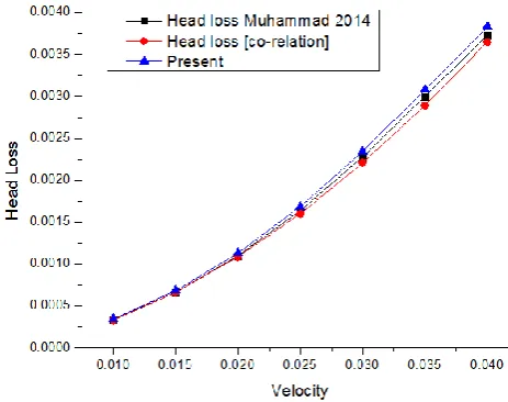
A validation has been illustrated from the figure 2 as on solving the governing equation as discussed above the validation of head loss of the circular pipe has been plotted
[image:3.595.284.555.54.290.2]Figure 2 Head loss validation of circular pipe
[image:3.595.311.558.330.518.2]Figure 3 Contour plot of Dynamic Pressure (Circular Duct)
[image:3.595.42.274.352.535.2]Figure 4 Contour plot of Dynamic Pressure (Triangular Duct)
[image:3.595.39.286.566.756.2]Figure 5 Contour plot of Dynamic Pressure (Rectangular Duct)
Figure 3 to figure 5 represent the Contour plot of Dynamic Pressure for circular, triangular and rectangular duct. It has been observed that triangular duct has maximum dynamic pressure at the outlet as compared to circular and rectangular duct. Moreover, on comparing dynamic pressure between circular and rectangular duct rectangular duct has higher dynamic pressure at the centre of the duct and at the outlet than the circular duct.
© 2017, IRJET | Impact Factor value: 5.181 | ISO 9001:2008 Certified Journal | Page 2073 Figure 6 Turbulent Intensity along the duct length
[image:4.595.315.566.242.408.2](Circular Duct)
Figure 7 Turbulent Intensity along the duct length (Triangular Duct)
Figure 8 Turbulent Intensity along the duct length (Rectangular Duct)
Figure 6 to figure 8 demonstrates turbulent Intensity along across circular, triangular and rectangular duct. It has been observed that the turbulent Intensity significantly increases after 4m in circular duct and similarly after 6m in triangular duct. While the turbulent Intensity across the rectangular duct continuously goes on increasing along the duct length. This is because of insignificant variation in boundary layer and viscous sub layer as there is no such obstruction in the flow. At high Remolds number the turbulent Intensity across the circular duct is more as compared to triangular and rectangular duct.
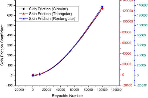
Figure 9 a comparison of skin friction coefficient between circular, triangular and rectangular duct.
Figure 9 shows the comparison of skin friction coefficient between circular, triangular and rectangular duct. It has seen that the skin friction coefficient gradually increases as the Reynolds number increases. The rate of augmentation of skin friction coefficient is noteworthy at higher Reynolds number. On comparative analysis triangular duct has more skin friction coefficient as compared to circular and rectangular duct. It has been found that the rectangular duct has 8.45% lower skin friction coefficient as compared to triangular duct at fully developed turbulent flow.
5. Conclusions
Following conclusions has been drawn from the comparative analysis fully developed turbulent flow in various arbitrary cross-section ducts using Finite volume approach.
Using k-ε turbulence model the turbulence intensity has been investigated for fully developed turbulent flow.
Triangular pipe has higher rate of turbulent intensity throughout the duct length as compared to the other ducts.
[image:4.595.37.286.332.521.2]© 2017, IRJET | Impact Factor value: 5.181 | ISO 9001:2008 Certified Journal | Page 2074 In terms of drop in pressure triangular pipe has
higher gradient as compared to other two ducts i.e. circular and rectangular.
It has been seen that at the centre of duct the velocity is maximum, while across the wall surface the value of velocity is minimum.
Similarly, it has been seen that in ducts the wall shear stress is maximum at the wall and it increases along the duct length and also increases as velocity enhances.
REFERENCES
P. Talukdar, M. Shah, Analysis of laminar mixed convective heat transfer in horizontal triangular ducts. Numer. Heat Transf. 54(A), 1148–1168 (2008)
H.C. Chiu, J.H. Jang, W.M. Yan, Mixed convection heat transfer in horizontal rectangular ducts with radiation effects. Int. J. Heat Mass Transf. 50, 2874– 2882 (2007)
H.C. Chiu, W.M. Yan, Mixed convection heat transfer in inclined rectangular ducts with radiation effects. Int. J. Heat Mass Transf. 51, 1085–1094 (2008) W.M. Yan, H.Y. Li, Radiation effects on mixed
convection heat transfer in a vertical square duct. Int. J. Heat Mass Transf. 44, 1401–1410 (2001) S. Chen, T.L. Chan, C.W. Leung, B. Yu, Numerical
prediction of laminar forced convection in triangular ducts with unstructured triangular grid method. Numer. Heat Transf. 38(A), 209–224 (2000)
Heris, S.Z., Nassan, T.H., Noie, S.H., 2011. CuO/water nanofluid convective heat transfer through square duct under uniform heat flux. Int. J. Nanosci. Nanotechnol. 7 (3), 111–120.
Tympel, S., Krasnov, D., Boeck, T., Schumacher, J., 2012. Distortion of liquid metal flow in a square duct due to the influence of a magnetic point dipole. Proc. Appl. Math. Mech. 12, 567–568
Sarma, D., Deka, P.N., Kakaty, S.C., 2014. Numerical study of liquid metal mhd flow through a square duct. Asian J. Current Eng. Maths 3 (2), 15–19. Kun, M.A., Shiwei, Yuan, Huaijian, Chang, Huanxin,
Lai, 2014. Experimental study of pseudoplastic fluid flows in a square duct of strong curvature. J. Therm. Sci. 23 (4), 359–367.
Ting, H.H., Hou, S.S., 2015. Investigation of laminar convective heat transfer for Al2O3-water nanofluids
flowing through a square crosssection duct with a constant heat flux. Materials 8, 5321–5335. Fabbri G. Heat transfer optimization in corrugated
wall channels. Int J Heat Mass Transf 2000;43(23):4299-310.
Zhang Z, Lowe R, Falter J, Ivey G. A numerical model of wave-and current-driven nutrient uptake by coral reef communities. Ecol Model 2011;222(8):1456-70.
Togun H, Kazi S, Badarudin A. A review of experimental study of turbulent heat transfer in separated flow. Aust J Basic Appl Sci 2011;5(10):489-505.
Di Nucci C, Russo Spena A. Mean velocity profiles of two dimensional fully developed turbulent flows. C R Mec 2012;340(9):629-40.
Wang Z, Chi X, Shih T, Bons J. Direct simulation of surface roughness effects with RANS and DES approaches on viscous adaptive Cartesian grids. 2004. AIAA Paper 2420.