Modeling Flight Software from Architectural
Design Patterns
Pavani Neelakantam
CVR College of Engineering Department of CSE Ibrahimpatam (M), R.R. District
A.P., India
ABSTRACT
This paper discusses how Software design patterns are applicable to Flight Software (FSW) domain. The application of design patterns is particularly important in this domain to improve the quality of software and reduce the flight software anomalies which lead to major losses. Generic architectural design patterns for real-time software components are customized to suit the flight software domain. This is illustrated using the Student Nitric Oxide Explorer (SNOE), which is a real world case study from National Aeronautics and Space Administration (NASA). The customized design patterns are validated and made executable templates which help an engineer when building software architectures.
General Terms
Design Patterns, Software Architecture, Unified Modeling Language.
Keywords
Software Architectural Design Patterns, UML 2.0, Student Nitric Oxide Explorer (SNOE), IBM Rational Rhapsody.
1.
INTRODUCTION
Software design patterns are “descriptions of communicating objects and classes that are customized to solve a general design problem in a particular context” [1].
This paper provides a set of design patterns that are applicable to a small satellite Student Nitric Oxide Explorer (SNOE). The design patterns are customized to suit the working of the satellite and are also validated using IBM Rational Rhapsody. The Design patterns are developed to leverage the benefits of Software Product Line (SPL) approach. The SPL concepts used in this approach are based on Product Line UML-Based Software Engineering (PLUS) methodology by Gomma [2].
The case study discussed in this paper is related to Flight Software domain [3]. This domain is chosen for this study, to improve the quality of software architectures in FSW domain and to reduce the number of flight software related anomalies. The industry trend indicates that the number of software related anomalies is growing. It is reported that “in the period from 1998 to 2000, nearly half of all observed spacecraft anomalies were related to software” [4]. These software anomalies can cause mission disruption or even mission loss. In the aerospace industry these losses cannot be tolerated because of the high cost and length of time that is required to build a spacecraft.
2.
TOOL SUPPORT: IBM RATIONAL
RHAPSODY DEVELOPER FOR JAVA
This paper uses a tool called IBM Rational Rhapsody 7.6.1 Developer for Java to build and execute the state machines [5]. The generic design patterns are customized and validated using the tool. IBM Rational Rhapsody is used to depict the functionality of the components in the design patterns using Rhapsody’s action language and Event handling infrastructure.
IBM Rational Rhapsody uses custom action language, to capture actions and to execute the model. Thus, this action language is used to implement the objects actions. The objects actions and the functionality of the components are depicted in state chart diagrams. The action language is similar to Java, except there are a few additional reserved words and functions. For example, GEN is a reserved word used to generate asynchronous messages as events. The messages must be specified on the consumer’s provided interface in order to be invoked.
Ex: PClass.gen(new evnt());
Where PClass is the port that allows communication with the outside environment. The port can be represented with the provided interface and the required interface. GEN is the reserved word that is used to specify the event that is generated. Here evnt() is the event that is generated. When an event is generated, IBM Rational Rhapsody event handling infrastructure handles the routing of events from the producer to the consumer. When the consumer component receives the event, the appropriate state transition is taken and actions within that state are performed. Thus, executable state charts represent the functional behavior of the components of the system.
IBM Rational Rhapsody is an excellent tool to create dynamic UML diagrams using Real-time UML that is UML 2.0. These executable state charts and Object Model Diagrams can be validated using Rational Rhapsody. Rhapsody is also used to generate code for the diagrams.
3.
UML 2.0 AS ARCHITECTURAL
DESCRIPTION LANGUAGE (ADL)
“The software architecture of a program or computing system is the structure or structures of the system, which comprise software elements, the externally visible properties of those elements, and the relationships among them” [6].
International Journal of Computer Applications (0975 – 8887) Volume 62– No.10, January 2013
system in terms of its architectural elements and the relationship among them” [7]. UML is widely accepted language by practitioners.
UML can be used to describe and model even software architectures. The most promising way of mapping software architectures to UML is using UML profiles such that those profiles are derived as mappings of ADLs. The architectures can be well expressed in UML than any ADL. The UML profile for scheduling, performance, and time specification described in [8] has been adopted as an official OMG standard in March 2002. The UML profile defines a domain specific interpretation of UML; it might be viewed as a package of specializations of general UML concepts that capture domain-specific variations and usage patterns. The UML extensibility mechanisms (i.e., stereotypes, tagged values, constraints) are used to interpret the functionality of the system in the diagrams.
The UML 2.0 diagrams are represented using the Component and connector views (C&C views, for short) [9]. They present architecture in terms of elements that have a runtime presence (e.g., processes, clients, and data stores) and pathways of interaction (e.g., communication links and protocols, information flows, and access to shared resources). Components are the principal units of run-time interaction or data storage. Connectors are the interaction mechanisms among components.
Components are created as Composite classes in UML 2.0 and each of the components should have ports to interact with the external environment. Each port again requires an interface for it to interact. The interfaces are of two types Provided Interface and Required Interface. Two components with ports and their interfaces can be linked for communication. The ports and their interfaces should be compatible, that is one component having a required interface (depicted as semi circle) can interact with only a component that provides the interface (depicted as full circle). It is through these port names that the message passing is done.
This paper presents the customized design patterns of SNOE using UML 2.0. The UML diagrams used are produced using IBM Rational Rhapsody. The diagrams that are used to represent the design patterns are the Object Model diagrams and the State Charts in Rhapsody.
4.
STUDENT NITRIC OXIDE
EXPLORER (SNOE)
SNOE, a real-world, small satellite program funded by the National Aeronautics and Space Administration (NASA) and managed by the Universities Space Research Association (USRA) [10]. This project describes the construction of architecture for SNOE by customizing and validating the selected design patterns.
SNOE’s job is to measure thermospheric Nitric Oxide (NO) and its variability in the low earth orbit. The SNOE spacecraft is spin stabilized, meaning it maintains its orientation similar to that of a top. SNOE is required to maintain a spin rate of 5 Rotations Per Minute (RPM). The spin rate can be adjusted having the Flight Software (FSW) send a command to commutate the electromagnet transverse torque rod.
SNOE’s FSW does not perform the attitude determination and control calculations. Rather, the FSW collects the attitude measurements and downlinks them to the ground for processing. Then the ground uplinks attitude control commands back to the spacecraft for the SNOE FSW to
execute. The attitude measurements are taken from two Horizon Crossing Indicators (HCI) and three Magnetometers. SNOE’s spacecraft body is surrounded on all sides by stationary solar panels which are used to generate power.
The spacecraft contains four payload instruments to accomplish its scientific mission. These four instruments are an Ultra Violet Spectrometer (UVS) that measures Nitric Oxide density, an Auroral Photometer (AP) that measures the flux of energetic electrons entering the Earth's upper atmosphere, Solar soft X-ray Photometer (SXP) that measures the solar irradiance and a microGPS Bit-Grabber Space Receiver (microGPS BGSR) which gathers position information based on the Global Positioning System (GPS) constellation for experimental orbital determination.
In addition to collecting science data and attitude control data, the SNOE FSW must also periodically collect health status and housekeeping data from the hardware. The FSW stores this data and sends it to the ground for processing and analysis.
4.1
SNOE Design Pattern Selection
The design pattern selection process is done using the command execution functionality of SNOE. This involves determining the order in which spacecraft commands are executed. The design patterns that support this feature are then selected. For example, on small spacecraft the Centralized Control Design Pattern is better suitable than the Distributed Control Design Pattern. The Centralized Control design pattern involves a single controller that provides overall control of all the components of SNOE. This can be illustrated by conceptually executing a state machine. This design pattern is useful on small spacecraft because it encapsulates all the state-dependent control in a single component thus making the control logic easier to understand and maintain. Thus, the design patterns that support SNOE specific features are determined by selecting the Design Patterns that are suitable for the working of SNOE. Seven different Design Patterns have been identified and customized to reflect the functionality of SNOE.
[image:2.595.319.547.526.749.2]The Design Patterns identified are listed in table 1.
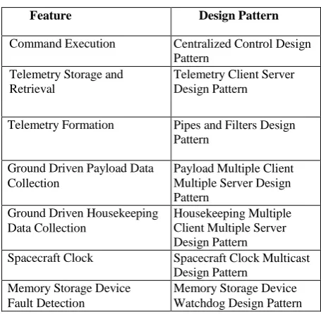
Table 1. SNOE Design Pattern Selection
Feature Design Pattern
Command Execution Centralized Control Design Pattern
Telemetry Storage and Retrieval
Telemetry Client Server Design Pattern
Telemetry Formation Pipes and Filters Design Pattern
Ground Driven Payload Data Collection
Payload Multiple Client Multiple Server Design Pattern
Ground Driven Housekeeping Data Collection
Housekeeping Multiple Client Multiple Server Design Pattern
Spacecraft Clock Spacecraft Clock Multicast Design Pattern
Memory Storage Device Fault Detection
Figure 1. Component diagram for SNOE Centralized Control executable design pattern
5. IMPLEMENTATION
5.1 SNOE Centralized Control Design
Pattern
The SNOE utilizes the Centralized Control design pattern to execute commands and control the overall operation of the spacecraft. The component diagram for SNOE’s Centralized Control design pattern is shown in figure 1.
SNOE contains thirteen components; therefore thirteen device components are created. For each component, the port name is updated to reflect the specific component, such as the RmGPS. The port’s interface is updated to reflect the specific functionalities that can be invoked on that instrument. The ports, interfaces, and connecters for the components are captured in the diagram.
Next, the executable version of the design pattern involves potentially adding states, actions, and activities to the state machines based on the functionality of the components.
Once the state machine for a component is built, a small icon for opening the statechart appears on the top right corner of the component. This icon acts like a link to open the respective statechart for the component from the Object Model Diagram.
The state machine for the EEPROM_IOC component is depicted in the fig. 2. This is an Input-Output component. The component begins in the Idle state within the Working state. In the Idle state the Component waits for commands from the Centralized_Controller. When an action message is received, it transitions to the Executing_Command state where it performs the appropriate actions on the external hardware. After it performs the necessary actions, it generates the processingComplete event and transitions back to the Idle
state to wait for the next command. When a read message is received, a similar set of states and transitions occurs, however, it occurs in the Gathering_Data state. The IO_Component is also responsible for listening to external events from the hardware. Therefore if an externalEvent event is received, the IO_Component stops its current action in the Working state and transitions into the Preparing_Notification state. In the Preparing_Notification state it prepares a message to send to the Centralized_Controller.
Once the message is ready, the IO_Component then sends the inputEventNotification message to the Centralized_Controller through the PEEPROM port and transitions back to its previously interrupted location within the Working state. This is depicted using a history connector in Rhapsody.
[image:3.595.319.562.556.723.2]International Journal of Computer Applications (0975 – 8887) Volume 62– No.10, January 2013 Next the state machine for the SNOE’s Reciever_IC
[image:4.595.55.284.188.350.2]component is depicted in fig. 3. Receiver is an input component. It is initialized by the Centralized Controller. It is first in the idle state and moves to the Preparing_Notification state when an external event occurs. Here it prepares the input_event_notification and sends it to the Centralized_Controller. A similar set of actions is performed in response to a read event message; however the requested data is collected and sent back the Centralized_Controller.
Figure 3. State Machine for Magnetometer_IC
The Output Component begins in the Idle state where is waits for commands from the Centralized_Controller(fig. 4). Once a command message is received, the Output_Component transitions into the Execute_Command state where it performs the appropriate actions on the external hardware. Once complete, it generates the transmitData event and transitions back to the Idle state to wait for the next command.
Figure 4. State Machine for Low_Gain_Antenna_OC
Finally, the state machines for the other input, output, and IO components are also added.
5.2 SNOE HouseKeeping Multiple Client
Multiple Server Design Pattern
The next executable design pattern realized in SNOE is the FSW HouseKeeping Multiple Client Multiple Server design pattern. This design pattern is used to selectively collect data regarding the health and working of each of the components of SNOE. Since SNOE is required to collect the information to keep track of the health of the components, separate clients
are created for each instrument. Additionally, since each instrument has its own data buffer, separate server components are created to store the information collected.
This information collected is taken care by Telemetry Client Server Design pattern. It collects such information from all the components and sends it to the ground station for processing. The ground station sends commands back to the controller of the satellite if needed.
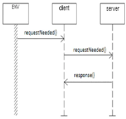
[image:4.595.328.532.293.486.2]The SNOE HouseKeeping Multiple Client Multiple Server design pattern involves selectively collecting information about the components. The interaction diagram for collecting housekeeping data is depicted in fig. 5. The controller sends a message to the client to collect the housekeeping data. The client sends a requestNeeded() message to the server and server then sends a response() to the client. This scenario applies to all the client and server components in the HouseKeepingClientServer Design pattern.
Figure 5. House Keeping Client-Server data scenario for SNOE
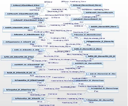
The component diagram in fig. 6 depicts the set of components in the system. The ports and connectors added between the appropriate clients and servers are also depicted in the diagram. Additionally, the interfaces are also updated to reflect the SNOE’s components. The interfaces should define all the methods that the respective components pass among each other for message communication. The diagram shows that the connected components have compatible interfaces. The message passing between each of the components happens when the message being called is defined in the provided interface of the consumer. For message passing, the components port name should be specified and the message to be passed should be specified with the GEN keyword of Rhapsody. This is depicted in the state chart diagrams which depict the behavior of the component.
[image:4.595.56.293.482.599.2]Figure 6. Object Model Diagram for HouseKeeping Multiple Client Multiple Server
In addition to updating the architectural views, the executable version of the design pattern also needs to be customized for SNOE. This is performed for each client and server in this design pattern. The specific steps involved in updating the state machine are follows.
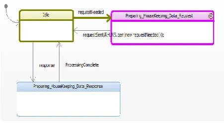
First, the HouseKeeping information from the Ultra Violet Spectrometer component of SNOE is collected. The House Keeping Ultra Violet Spectrometer Client (HUVS_DClient) component is responsible for collecting the data from the HUVS_DServer. The state machine for the SNOE specific HUVS_DClient component is depicted in fig. 7.
When Controller requires data it sends requestNeeded message to HUVS_DClient. HUVS_DClient requests the data from the server; this information is added to the actions on the state machine. This information is captured on the transition from the Preparing_HouseKeeping_Data_Request state to the Idle state. The event that occurs is the requestSent and the action
RHUVS.gen(new request());
indicates that a request for house keeping data is being sent to the HUVS_DServer component by specifying the required
port (RHUVS) of the client through which the components communicate. Finally, the SNOE specific processing logic within the Preparing_HouseKeeping_Data_Request state is added as On Entry actions.
Figure 7. State Machine for House Keeping Client
[image:5.595.318.547.562.704.2]International Journal of Computer Applications (0975 – 8887) Volume 62– No.10, January 2013
[image:6.595.57.282.100.186.2]processing is complete, the server prepares a response and moves back to the Idle state.
Figure 8. State Machine for House Keeping Server
Similarly, the state machines for client and server for the all the instruments of SNOE are also updated following a similar process.
The Object Model Diagrams and state machines for all the identified design patterns are developed and validated using IBM Rational Rhapsody.
6.
RESULTS
This paper validates the design patterns using the tool IBM Rational Rhapsody. Rational Rhapsody generates the code for the design patterns and validates the design patterns using ‘build’ option. Thus the functionality of design patterns can be verified during the design phase and reduce the number of anomalies in flight software. This validation of design patterns for functional correctness was not possible in static UML diagrams. Rational Rhapsody also enables the animation of statecharts by generating events to check the behavior of the component. The fig. 9 is an example of animated statechart of client component where the bright colored state indicates the present state of the component after the requestNeeded event is generated.
Figure 9. Animated State Chart for Client
Thus the functionality of every component in the design pattern can be validated to build an error free Architecture.
7.
CONCLUSIONS
This paper illustrates an approach for building software architecture from software architectural patterns. This approach improves the quality of FSW architecture. The executable design pattern templates help an engineer when building software architectures and also provide the foundation for performing design time validation on the software architecture produced using this approach. The
engineers also can use these design patterns to form the core base for building the software architecture of any other system in this domain. Thus, enabling the Software Product Line (SPL) based product development.
8. FUTURE ENHANCEMENTS
There are several avenues of future research that can be taken to extend this paper. First, the SNOE case study can be expanded to include performance validation using MARTE (Modeling and Analysis of Real-Time Embedded systems) stereotypes. Second, this work can be applied to other DRE domains to illustrate the approach’s applicability across DRE domains. Additionally, future research can include illustrating the functionality of the design patterns by animating the sequence diagrams using the “animation” feature of IBM Rational Rhapsody.
9. REFERENCES
[1] Gamma, E. et al., 1995. Design Patterns: Elements of Reusable Object-Oriented Software, Addison-Wesley Professional Computing Series
[2] H. Gomaa. 2005. Designing Software Product Lines with UML: From Use Cases to Pattern-Based Software Architectures. Addison-Wesley Object Technology Series.
[3] H. Gomaa, G.A. Farrukh, 1998 Composition of Software Architectures from Reusable Architecture Patterns, ISAW '98 Proceedings of the third international workshop on Software architecture, ACM New York .
[4] Julie Street Fant, Hassan Gomaa, Robert G. Pettit. 2011. Architectural Design Patterns for Flight Software. 14th IEEE International Symposium on Object/Component/Service-Oriented Real-Time Distributed Computing Workshops.
[5] D. Harel. 1997. Executable object modeling with statecharts. 18th International Conference on Software Engineering.
[6] Len Bass, Paul Clements, Rick Kazman, 2003. Software Architecture in Practice. Addison-Wesley.
[7] B.Bharathi, Dr.D.Sridharan. 2009. UML as an Architecture Description Language. International Journal of Recent Trends in Engineering.
[8] Clements. P. et.al. 2002. Documenting Software Architectures, Views and Beyond. Addison-Wesley. Boston, MA, USA.
[9] Software Architecture Description & UML Workshop, Hosted at the 7th International Conference on UML Modeling Languages and Applications <<UML>> 2004, October 11-15, 2004, Lisbon, Portugal.
[10]Laboratory For Atmospheric and Space Physics at the University of Colorado at Boulder. Student Nitric Oxide
Explorer Homepage. 2010.
[image:6.595.55.281.487.613.2]