6
I
January 2018
Design of Asynchronous Viterbi Decoder Using
Pipeline Architecture
Girish D. Korde1, Sanjay L. Haridas2 1
Research Scholar, Dept. of ETRX Engg. B. D. College of Engineering, Sevagram, Wardha (M.S.),India
2
Professor, Dept. of EXTC Engg. G. H. Raisoni College of Engineering, Nagpur (M.S.), India
Abstract: Low power asynchronous Viterbi decoder designed based on pipeline architecture has been presented in this paper. Complete circuit is operating in the pipelined manner to achieve low power. Asynchronous Viterbi decoder for code rate 1/2 and constraint length 3 is designed in VHDL. Power dissipation is investigated and compare with the synchronous design of Viterbi decoder. Register exchange is well known method used to design Viterbi decoder. To reduce the power consumption of Viterbi decoder hybrid register exchange method is used to reduce the switching activity of register exchange method and hence the dynamic power. Proposed asynchronous pipelined HRE method helps to reduce average dynamic power by 19.44% than its synchronous design and 7.14% in RE method. Xpower analyzer tool of Xilinx13.1 is used to calculate the dynamic power. Keywords: Viterbi Decoder, Viterbi Algorithm, RE, HRE, Pipeline, ACS, BMU.
I. INTRODUCTION
In the present era, wireless technology is one of the emerging technologies in the field of communication engineering. It is advanced form telephony to cellular communication and now satellite communication. Since the beginning of cellular mobile network in 1990 mobile technology has grow very rapidly. First mobile phone was appeared in 1980 which was based on first generation (1G) analog technology depends on FDMA. In 1990s the second generation (2G) mobile was arrived after ten years gap between 1G and 2G which was depends on TDMA and CDMA technology. Now a day third generation (3G) and fourth generation (4G) handsets are booming in the market. These are depends on CDMA 2000 and WCDMA [4] technology. Viterbi decoder is the part of WCDMA mobile terminal which is investigated in this study to reduce the power consumption of VD.
Viterbi [1, 2] decoder was firstly introduced in 1967 by Andrew J. Viterbi which was modified in 1971[3] by Forney considering it is the best suited for decoding the maximum likelihood sequence. Broadly there are two main decoding methods viz: trace back (TB) method and register exchange (RE) method [8]. Trace back method is widely used for decoding in Viterbi decoder for large constraint length. In this method, it requires last in first out (LIFO) register to trace the decoded sequence. So it requires large memory and also the switching activity is more in case of this method. In register exchange method, register is assigned to each state which is frequently switching for every decoded bit sequence. As the switching activity is high in register exchange this method also consumes large power. To reduce the power consumption of decoder one has to reduce the supply voltage as technology changes or reduce the switching activity. Hybrid register exchange (HRE) method [7] can be the solution for this which is combination of trace back method and register exchange method. Viterbi decoder consists of three basic computation units. The branch metric unit (BMU) used to calculate the branch metric. Add-compare-select (ACS) unit computes the path metric from branch metric and current state metric. Survivor memory unit process the decision bit received from ACS and output the decoded bits. Asynchronous Pipeline [5] [6] is introduced between the different blocks of Viterbi decoder design to achieve the low power. This paper is organized as follows section II presents a brief description about convolution code. Different decoding methods are explained in section III. Implementation of proposed asynchronous Viterbi decoder is described in section IV. Simulation results and discussion is elaborated in section V. A conclusion will be presented in section VI.
II. CONVOLUTION ENCODER
The convolutional encoder is basically a finite state machine. To encode the input data we can use convolutional encoder (n, k, K),
where, k is the number of input bits, n is number of output bits, and a constraint length is K. There are 2K−1 states in VD. Therefore,
there are 2K−1 surviving paths at each stage, and 2K-1 metrics, one for each surviving path. For the formal specification, here we use
(2, 1, 3) convolutional code. Thus, we can defined that the number of states in the trellis is 4. The generator polynomial for the
encoder is given by: i1 = [1, 0, 1] and i0 = [1, 1, 1]. Generator polynomial specifies the connections of the encoder to the modulo-2
Two memory elements will require for designing convolution encoder for code rate 1/2 and constraint length 3 as depicted in figure 1. The constraint length K denotes the length of the convolutional encoder. Convolutional encoder increases the length of the message sequence by adding redundant bits in order to increase the likelihood of detecting the transmitted sequence. Encoder design will work in serially time shifted data sequence manner. It involves the modulo-2 addition to generate output of selected input bit.
Figure 1: Convolution Encoder for (2, 1, 3)
= ⨁ ⨁ − − − − − − 1
= ⨁ − − − − − − 2
III. DECODING METHOD
Viterbi decoder can be decoded using different methods. Here two decoding methods are discussed in detailed. Decision bits are process to receive the decoded output.
A. Register Exchange (RE) Method
[image:3.612.137.480.501.632.2]Register Exchange method is simpler and commonly used technique. In this method SMU is constructed using bank of registers connected in same manner as the trellis diagram. As shown in Figure 2, register is assigned to each state contains information bits for the survivor path through the trellis. Register keeps record of partially decoded output sequence along the path. The register exchange method eliminates the need to trace-back since the register of final state contains the decoded output.
Figure 2: Example of Register Exchange Method
For instance, at time t1 the survivor branch for S1 state is from S0 state at t0; therefore, content of the S1 state becomes “1” at t1 and
the corresponding decoded data for the survivor branch, which is a “1”, is appended to it. At time t2 the survivor branch for S3 state
is from S1 state at t1; therefore the initial content of S1 state register, which is “1”, is shifted into S3 state register at t2 and the
corresponding decoded data for the survivor branch, which is “1”, is appended to it. So the content of S3 state register becomes 11.
At time t3 the survivor branch for S2 state is from S3 state at t2; therefore the initial content of S3 state register, which is “11”, is
content of S2 state register at t3 becomes 110. This process goes continue till the end of encoded bit, the final state register of S0
contains the decoded output. So the register assigned to each state contains information bits for the survivor path from the initial state to the final state. Bold arrow (indicated in green color) is global winner path. However, this method results in complex hardware due to the need to copy the contents of all the registers from current stage to the next stage.
B. Hybrid Register Exchange (HRE) Method
Drawback of register exchange method can be overcome by using HRE method. Hybrid register exchange method is the combination of register exchange method and trace-back method, which reduce the switching activity and power. Property of trellis is being used to decode the sequence by using HRE method. By the property of trellis if we go forward for m cycles then the data bits will be the corresponding state bits irrespective of the initial state from where the data gets transferred. To find the initial state one has to trace back through an m cycle by observing the survivor memory. And then transfer the partial decoded data from initial state to the next state which is m cycle latter and not a subsequent cycle. Memory operation is not in every clock cycle, and it gets reduced by factor m. In this way shifting of data from one register to another is reduced and hence the switching activity and ultimately power consumption will get reduced.
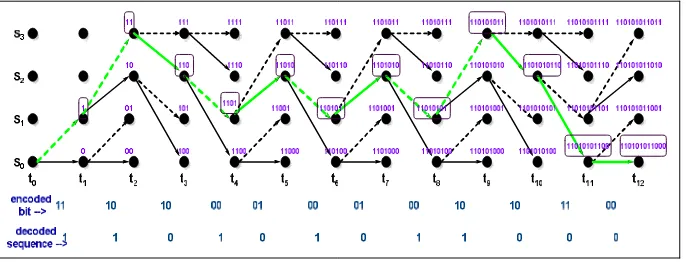
Figure 3 illustrate example of hybrid register exchange method. If the current state is S3, the survivor state is S2, and the data input is
11. So the previous data from S2 will get transferred to S3 and new data is added as 11. From the figure 3 survivor state at t4 is “11”
for state S1 therefore the content of S3 state register at t2 is shifted into S1 state register at t4 and the corresponding decoded data for
the srvivor branch, which is “01”, is appended to it. So the content of S1 state register at t4 becomes 1101.
Survivor state at t6 is “1101” for state S1 therefore the content of S1 state register at t4 is shifted into S1 state register at t6 and the
corresponding decoded data for the survivor branch, which is “01”, is appended to it. So the content of S1 state register at t6 becomes
110101. This process goes continue, the final state register of S0 contains the decoded output. So in HRE method register are
[image:4.612.117.497.378.602.2]updated at every alternate clock cycle. Bold arrow (indicated in green color) is the winner path in hybrid register exchange method.
Figure 3: Example of Hybrid Registers Exchange Method
III. IMPLEMENTATION OF PIPELINED ARCHITECTURE
Figure 4: Asynchronous Viterbi Decoder Using Pipeline Architecture
Output of encoder is process through noise module. Generated noisy signal is route through register (reg1) to branch metric unit for
calculation of branch metric. Clock signal with 1800 phase shift is applied to the reg1. The BMU generate the branch metric values
and process to the ACS unit through reg2. In ACS unit add-compare-select operation is performed to generate the output decision bit for SMU. Path metric memory (PMM) consists of reg3, integrated between input and output of ACS. Parallel to serial shift register is used at the end of SMU to receive the output serially. Each register is associated with a separate clock signal. Different
clock signal will require for synchronizing all the registers used. Clock to reg1 is having 1800 phase shift with respect to original
clock.
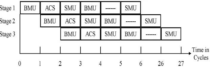
Figure 5: Basic Structure of Execution of Pipelined Viterbi Decoder
Pipelined execution of Viterbi decoder is shown in figure 5 [5]. Pipelining is carried out between BMU, ACS and SMU where numbers of instructions are overlapped in execution. It never reduces the individual instructions time for execution.
Asynchronous pipeline is faster. The reason for the improvement is at the completion of every stage, the data is determined individually, in spite of evaluating the worst case delay of the slowest stage (using a global clock). In asynchronous pipeline there are two different types of stalls and in both, a clock is used in the synchronous version. In stage2 the first is demonstrated and then BMU is move to stage3. Here the new data is accepted by the stage2 hardware but ACS is yet to complete its function in stage1. This period is called starvation, since the data is not available and the hardware has to wait for the data. In the second type of stall, SMU starts its movement stage1 to stage2 but the stage is not prepared to accept new data since BMU is processed. Consequently blocking occurs since the data is readily available but it will have to wait for the availability of the hardware. When a small number of data elements are present in the pipeline, then starvation occurs and hence the throughput is low. At the same time when many data elements are present in the pipeline, then blockings occurs and causes high latency. Hence the balanced pipeline will have low latency and high throughput.
The ACS module is composed of two units of butterfly module. ACS module is used to calculate the new path metric and decision bit. Generated path metric is store in path metric memory i.e. reg3 and is use to calculate new path metric. Register, reg2 is 4bit PIPO shift register used to latch the data generated from BMU. Similarly reg3 is designed as 8bit PIPO shift register which process the path metric. Counter is used to count the timing instance of each switching activity at all four state.
[image:5.612.131.483.342.460.2]Figure 6: RTL View of Asynchronous Viterbi Decoder Using Pipeline Architecture for HRE Method
IV. SIMULATION RESULTS
Figure 7 & figure 8 shows that the simulation results of asynchronous Viterbi decoder using pipelined architecture for register
exchange and hybrid register exchange method. Input sequence applied is 12 bit 110101011000; at the end of 12th clock cycle
complete decoded data is received.
Figure 7: Simulation Waveform of Viterbi Decoder Using Pipeline Architecture for RE Method
[image:6.612.154.452.77.244.2]Dynamic power is can be calculated by equation 3. It mainly depends on the switching activity of the circuit, frequency of operation, load capacitance and supply voltage and is given by
=∝∗ ∗ ∗ − − − − 3
Where α is switching activity, CL is load capacitance, V is supply voltage and f is operating frequency and. Table 1 show the dynamic power dissipation of Viterbi decoder designed using synchronous and asynchronous pipelined architecture for register exchange and hybrid register exchange methods. Comparison between the synchronous architecture and pipelined asynchronous architecture of Viterbi decoder with respect to dynamic power dissipation is given in Table 1.
Table 1: Dynamic Power Using RE and HRE Method
Synchronous RE Pipelined RE Synchronous
HRE
Pipelined HRE
Dynamic Power in mW
0.42 0.39 0.36 0.29
V. CONCLUSION
In this paper we designed low power asynchronous Viterbi decoder using pipelined architecture for register exchange and hybrid register exchange methods for constraint length K=3 and code rate 1/2.The design of asynchronous Viterbi decoder for input bit sequence 110101011000 has been simulated and power analysis is done using Xpower analyzer of Xilinx 13.1.It has been observed that register is updating contain in alternate clock cycle in HRE method; hence the switching activity is reduced in this method than RE method. As the switching activity is reduced in HRE method dynamic power obtained is less as compared to RE method. About 7.14% dynamic power is reduced in RE method with the use of asynchronous pipelined architecture and 19.44% in HRE method over its synchronous design. Complete design is implemented using VHDL in Xilinx 13.1 Spartan3E family and the target device is xc3s100e-5vq100.
REFERENCES
[1] Andrew J. Viterbi, “Error Bound For Convolutional Codes and an Asymptotically Optimum Decoding Algorithm”, IEEE Trans. On Information Theory, Vol. IT-13, No, 2, April 1967, pg. 260-269.
[2] Andrew J. Viterbi, “Convolutional Codes and Their Performance in Communication Systems”, IEEE Trans. On Communication Technology, Vol. 19, Issue 5, October 1971, pg. 751-772.
[3] G. David Forney, “ The Viterbi Algorithm”, Proceedings of the IEEE, Vol. 61, No. 3, March 1973, pg. 268-278.
[4] Dalia Abdel-WahedFouad El-Dib, “Low Power Register Exchange Viterbi Decoder for Wireless Applications”, PhD thesis Waterloo, Ontario, Canada, 2004. [5] C. Arun, V. Rajamani, “A Low Power and High Speed Viterbi Decoder Based on Deep Pipelined, Clock Blocking and Hazards Filtering”, Int. Journal
Communication, Network and System Sciences, 2009, 6, 575-582, DOI: 10.4236/ijcns.2009.26064.
[6] Nayel Al-Zubi, “Pipelined Viterbi Decoder Using FPGA”, Research Journal of Applied Sciences, Engineering and Technology 5(4) 2013, ISSN: 2040-7459; e-ISSN: 2040-7467, Pg 1362-1372.
[7] S. L. Haridas, Dr. N. K. Choudhari, “Design of Viterbi Decoder with Modified Trace-back and Hybrid Register Exchange Processing”, Int. conf. ACAC3’09, January 2009, ACM 978-1-60558-351-8.