5
X
October 2017
Stability Improvement of FSIG based Grid
Connected Wind Farm Using STATCOM/SVC
during different Fault Locations
Sapna Maheshwari 1, Dr. G. C. Biswa2 1,2
Department of Electrical Engineering, B.I.T, Durg, Chhattisgarh, INDIA
Abstract-The effect of fault locations on the behavior of the FSIG based wind farm interconnected grid during different fault types is investigated in this paper. The effects of fault locations are studied for different fault types. The contribution of Static Synchronous Compensator STATCOM and Static Var Compensator (SVC) to support the FSIG based wind farm interconnected electric grid during different fault locations are investigated. The wind farm terminal voltage, the exported active power, and the absorbed reactive power are monitored in different fault conditions.Simulation test cases using MATLAB-Simulink are implemented on a 13.5 MW wind farm exports power to a 220 KV grid.
Keywords-Static Var Compensator (SVC); Static Synchronous Compensator (STATCOM); Fixed Speed Induction Generator (FSIG).
I. INTRODUCTION
An increasing demand for more electric power coupled with depleting natural resources has led to an increased need for energy production from renewable energy sources such as wind and solar. The recent technological advancements in wind energy conversion and an increased support from governmental and private institutions have led to increased wind power generation in recent years. Wind power is the fastest growing renewable source of electrical energy. In the past, the total installed wind power capacity was a small fraction of the power system and continuous connection of the wind farm to the grid was not a major concern. With an increasing share derived from wind power sources, continuous conection of wind farms to the system has played an increasing role in enabling uninterrupted power supply to the load, even in the case of minor disturbances.
Voltage stability and an efficient fault ride through capability are the basic requirements for higher penetration. Wind turbines have to be able to continue uninterrupted operation under transient voltage conditions to be in accordance with the grid codes [2]. Grid codes are certain standards set by regulating agencies. Wind power systems should meet these requirements for interconnection to the grid. Different grid code standards are established by different regulating bodies, but Nordic grid codes are becoming increasingly popular [3].One of the major issues concerning a wind farm interconnection to a power grid concerns its dynamic stability on the power system [4]. Voltage instability problems occur in a power system that is not able to meet the reactive power demand during faults and heavy loading conditions. Stand alone systems are easier to model, analyze, and control than large power systems in simulation studies. A wind farm is usually spread over a wide area and has many wind generators, which produce different amounts of power as they are exposed to different wind patterns.
In past years, various researchers have studied the performance improvement methods using FACTS devices that are being researched upon in the field of grid connect wind farm network. The flexible alternating current transmission systems (FACTs) devices are the most suitable promise tools for voltage and dynamic stability improvement of wind energy systems connected to grid as well as sand alone. There are many useful types of FACTs devices are applied successfully for improving the dynamic stability of wind energy systems connected to grid. Flexible AC Transmission Systems (FACTS) such as the Static Synchronous Compensator (STATCOM) and the Unified Power Flow Controller (UPFC) are being used extensively in power systems because of their ability to provide flexible power flow control [5]. Static synchronous compensators (STATCOM) and static VAR compensators are used widely for improving the voltage and dynamic stability of wind energy systemss
considerably improve wind farm stability [7]. In comparison with SVC, STATCOM is best choice for increasing stability of grid connected wind farms. It is necessary to examine the responses of SCIG wind farm during the faults
and possible impacts on the system stability. In this paper, theimpacts of fault location on 13.5 MW windfarm interconnected grid are studied by monitoring the activepower, reactive power, and bus voltage of the wind farm. Also,the contribution of STATCOM and SVC to support the wind farm duringdifferent fault locations are studied.
II. SIMULATED NETWORK
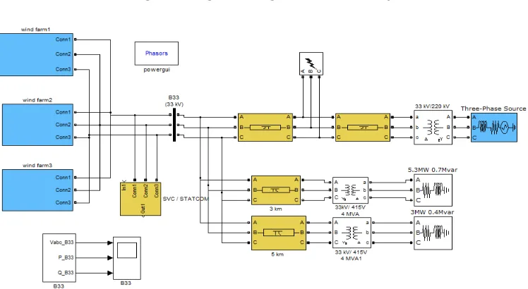
[image:3.612.138.496.266.377.2]The single line diagram of a typical fixed speed wind power plant under study is shown in Figure 1. The simulation model is carried out using the MATLAB SimPowerSystems toolbox. A power system model of wind farm distribution network is shown in Figure 2. The system consists of a 220 KV,50-Hz, sub transmission system with short circuit level of 2500 MVA, feeds a 33 KV distribution system through 220 kV/33 V step down transformer. A test system consisting of three wind farm of 13.5 MW (each 4.5 MW) and each wind farm having three equal capacity (1.5 MW) wind turbine induction generators (WTIGs) are connected to the 33 KV distribution system, exports power to 220 KV grid through a 50 km transmission line and two loads have been connected to the network.
Figure 1: Single line diagram of the studied system
Figure 2: Simulation model of Wind Farm distribution network
[image:3.612.121.495.393.598.2]III. SIMULATION SCENARIO
The test system is studied at steady state condition and fault state condition. At the fault state, the voltage, active power and reactive power are monitored at the main bus B33. The behavior of the wind power plant is recorded during fault events and after fault clearance. The studied wind farm operates at the nominal wind speed of 11 m/s, so the wind turbines operate at nominal values. During fault period, it can be assumed that the wind speed does not change and to study the effect of various fault types and fault location, the simulation is performed when the fault occurs at points P1 and P2 as shown in Fig. 1. The first faults location at the point P1 about 1 km from the wind turbines and the second fault location at the point P2, about 49 km from the main wind farm main bus B33. The system is studied thrice: one without STATCOM/SVC connection, second with STATCOM connection and other with SVC connection.
IV. SIMULATION RESULTS AND DISCUSSIONS
The effect of fault location on the stability of the wind farm connected grid are studied for different fault types as single line to ground fault, double line to ground fault, and three-line to ground fault. To study the effect of fault location on the behavior of the wind farm, the operation of the wind farm under different fault types are monitored twice, one when the fault occurs at the first fault location P1 about 1 km from wind turbines, and the other when the fault occurs at the second fault location P2 about 49 km from wind turbines. The effect of a 20 MVAR STATCOM and 20 MVAR SVC on the behavior of the wind farm are studied for all cases.
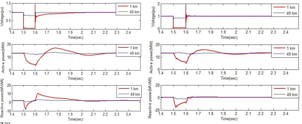
[image:4.612.43.558.391.604.2]A. Effect of Fault LocationUnder LG Fault
Fig. 3-5 shows the variations of wind farm terminal voltage, generated active power, and absorbed reactive power when a single line to ground fault occurs at the points P1 and P2. A constant wind speed of 11 m/s is applied to the wind turbine. It is clear from Fig. 3-5 that during the fault at point P1 the voltage, active power reduces drastically (when a fault is applied at 1.3-5 sec and cleared at 1.6 sec.) as compared to fault at P2. And the total reactive power absorbed from grid increase when fault occurs at point P1 as compared to fault at point P2. After fault clearance the wind farm equipped with STATCOM is reaching steady state soon as compared to
SVC.
Figure 3: Variations of the voltage, active power, and
total absorbed reactive power during single line to
ground fault at different fault locations – without
STATCOM/SVC
Figure 4: Variations of the voltage, active power, and
total absorbed reactive power during single line to
ground fault at different fault locations – with
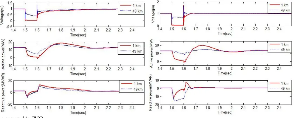
B. Effect of Fault Location Under LLG Fault
Fig. 6-8 shows the variations of wind farm terminal voltage, generated active power, and absorbed reactive power when a double line to ground fault occurs at the points P1 and P2. A constant wind speed of 11 m/s is applied to the wind turbine. It is clear from Fig. 6-8 that during the fault at point P1 the voltage, active power reduces drastically (when a fault is applied at 1.5 sec and cleared at 1.6 sec.) as compared to fault at P2. And the total reactive power absorbed from grid increase when fault occurs at point P1 as compared to fault at point P2. After fault clearance the wind farm equipped with STATCOM is reaching steady state soon as
compared to SVC.
Figure 5: Variations of the voltage, active power, and total absorbed reactive power during
single line to ground fault at different fault locations – with SVC
Figure 6: Variations of the voltage, active power, and
total absorbed reactive power during double line to
ground fault at different fault locations – without
STATCOM/SVC
Figure 7: Variations of the voltage, active power, and
total absorbed reactive power during double line to
ground fault at different fault locations – with
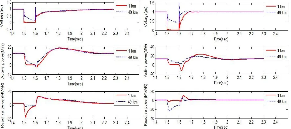
[image:5.612.39.545.430.632.2]Figure 8: Variations of the voltage, active power, and total absorbed reactive power during double line to ground fault at
different fault locations – with SVC
[image:6.612.46.550.438.661.2]C. Effect of Fault Location Under LLLG Fault
Fig. 9-11 shows the variations of wind farm terminal voltage, generated active power, and absorbed reactive power when a three line to ground fault occurs at the points P1 and P2. A constant wind speed of 11 m/s is applied to the wind turbine. It is clear from Fig. 9-11 that during the fault at point P1 the voltage, active power reduces drastically (when a fault is applied at 1.5 sec and cleared at 1.6 sec.) as compared to fault at P2. And the total reactive power absorbed from grid increase when fault occurs at point P1 as compared to fault at point P2. After fault clearance the wind farm equipped with STATCOM is reaching steady state soon as compared to SVC.
Figure 9: Variations of the voltage, active power, and total
absorbed reactive power during three line to ground fault at
different fault locations – without STATCOM/SVC
Figure 10: Variations of the voltage, active power, and total
absorbed reactive power during three line to ground fault at
Figure 11: Variations of the voltage, active power, and total absorbed reactive power during three line to ground fault at
different fault locations – with SVC
V. CONCLUSIONS
The effect of fault locations on the behavior of the FSIG based wind farm interconnected grid during different fault conditions are studied in this work. Also, the impacts of the Static Synchronous Compensator STATCOM and Static Var Compensator (SVC) on the stability of the system during different fault locations are studied. A simulation model of 13.5MW FSIG based wind farm interconnected grid is investigated. The wind farm terminal voltage, the exported active power, and the absorbed reactive power are monitored in different fault conditions. The fault occurs at two fault locations P1 and P2. Where P1 is located at 1 km from the wind turbines and P2 is located at 49 km from then wind turbines.
By studying the effect of fault location, in the cases of single line to ground fault and double line to ground fault and three line to ground fault it can be concluded that the STATCOM provides better wind farm voltage stability as compared to that with SVC during after fault occurrence. In fault case system with STATCOM gives more voltage, large active power, low value of reactive power supplied by grid to wind farms as compared to that of SVC. The STATCOM has better performance than that of SVC and also STATCOM has faster response than SVC. Thus, the large amount of wind power can be penetrated in to the grid without affecting the machine stability by controlling reactive power flow in the grid using STATCOM of suitable rating.
VI. ACKNOWLEDGMENT
I would like to sincerely thank Dr. G.C. Biswal, Associate Professor (Dept. of E.E.) who provided expertise that greatly assisted the research work.
REFERENCES
[1] Qusay. Salem, “Overall Control Strategy of Grid Connected to Wind Farm Using FACTS”, Bonfring International Journal of Power Systems and Integrated Circuits, Vol. 4, No. 1, February 2014.
[2] T. Sun, Z. Chen, F. Blaabjerg, “Voltage recovery of grid-connected wind turbines with DFIG after a short-circuit fault,” 2004 IEEE 35th Annual Power Electronics Specialists Conference, vol. 3, pp. 1991-97, 20-25 June 2004.
[3] M. Molinas, S. Vazquez, T. Takaku, J.M. Carrasco, R. Shimada, T. Undeland, “Improvement of transient stability margin in power systems with integrated wind generation using a STATCOM: An experimental verification”, International Conference on Future Power Systems, 16-18 Nov. 2005.
[4] E. Muljadi, C.P. Butterfield, “Wind Farm Power System Model Development”, World Renewable Energy Congress VIII, Colorado, Aug-Sept 2004.
[5] S.M. Muyeen, M.A. Mannan, M.H. Ali, R. Takahashi, T. Murata, J. Tamura, “Stabilization of Grid Connected Wind Generator by STATCOM”, IEEE Power Electronics and Drives Systems, Vol. 2, 28-01 Nov. 2005.
[6] MohamadAmiri, and Mina Sheikholeslami, “Transient Stability Improvement of Grid Connected Wind Generator using SVC and STATCOM”, International conference on Innovative Engineering Technologies (ICIET’2014) Dec. 28-29, 2014 Bangkok (Thailand).
[image:7.612.149.446.83.301.2][8] AtabakhshMojtaba, Ebadian Mahmoud, “Transient Stability Enhancement of Wind Farms using Flexible AC Transmission Technology (Comparison of SVC and STATCOM)”, International Journal of Innovative Technology and Exploring Engineering (IJITEE) ISSN: 2278-3075.
[9] S. N. Deepa& J. Rizwana, “Multi-Machine Stability of a Wind Farm Embedded Power System using FACTS Controllers”, India International Journal of Engineering and Technology (IJET), Vol 5 No 5 Oct-Nov 2013, ISSN: 0975-4024.
[10] Yuvaraj V, S N Deepa, A P Roger Rozario, Madhusudan Kumar, “Improving Grid Power Quality with FACTS Device on Integration of Wind Energy System”, Anna university of Technology Coimbatore, India Student Pulse.
[11] Kumar, V. S., Zobaa, A. F., &Kannan, R. D., “Power Quality and Stability Improvement in Wind Park System”, Jordan Journal of Mechanical and Industrial Engineering Volume 4, Number 1, Jan. 2010 ISSN 1995-6665.
[12] Vireshkumar G. Mathad, Basangouda F. Ronad , Suresh H. Jangamshetti, “Review on Comparison of FACTS Controllers for Power System Stability Enhancement”,International Journal of Scientific and Research Publications, Volume 3, Issue 3, March 2013, ISSN 2250-3153.
[13] Sidhartha Panda and N.P.Padhy “Power Electronics Based FACTS Controller for Stability Improvement of a Wind Energy Embedded Distribution System”, International Journal of Electronics, Circuits and Systems Volume 1 Number 1.
[14] A. Adamczyk, R. Teodorescu, R.N. Mukerjee, P. Rodriguez, “Overview of FACTS Devices for Wind Power Plants Directly Connected to the Transmission Network”, IEEE transactions 3742–3748.